Table of Contents
Advertisement
Quick Links
Advertisement
Table of Contents

Related Manuals for Maxxus 90R Pro


Summary of Contents for Maxxus 90R Pro
- Page 1 MAXXUS 90R PRO Bike...
- Page 2 This publication may not be reproduced, stored in a retrieval system, or transmitted in whole or in part, in any form or by any means, electronic, mechanical, photocopying, recording, or otherwise without the prior written permission of Maxxus Group GmbH & Co. KG.
-
Page 3: Safety Instructions
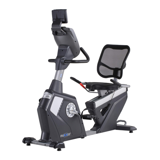
− It is recommended permanently to place a MAXXUS® Floor Protection Mat under the device to protect damageable floors such as wood, laminates, floor tiles etc. Please ensure that the mat cannot slip or slide. - Page 4 Overview of the Device Tablet holder Cockpit Handlebars Back rest Handlebar Shaft Pedal Stand with Transport Rollers Stand with transport handle...
- Page 5 Fixing Materials Teil 43 Teil 41 Teil 44 Teil 42 Unterlegscheibe Ø8 Federscheibe Ø8 Unterlegscheibe Ø10 Federscheibe Ø10 3 Stück 3 Stück 6 Stück 6 Stück Teil 19 Teil 20 Teil 24 Teil 25 Innensechskantschraube Innensechskantschraube Innensechskantschraube Innensechskantschraube M10x20 M8x20 M8x15 M6x15 4 Stück...
- Page 6 Assembly Carefully unpack all parts of the delivery. Two people are required because some parts of your training device are bulky and heavy. Before starting the assembly, check the completeness of the fixing materials (screws, nuts, etc.) and the components against the parts and fixing material lists on the previous pages of this manual. Carefully carry out the installation, as damage or defects that have arisen due to assembly errors are not covered by the warranty under any circumstances.
- Page 7 Assembly Step 3: Mounting the handlebar shaft Slide the handlebar stem cover (71) onto the handlebar shaft (2) from below. Make sure that the covers are correctly aligned. Insert the M12x70 set screws (22) into the seat of the base frame (1) for the handlebar shaft and tighten them slightly so that they grip.
- Page 8 Assembly Step 5: Mounting the handlebar Fasten the handlebar (9) to the handlebar shaft (2) with three hexagon socket screws M8x20 (20), three spring washers Ø8 (43) and three washers Ø8 (41). Step 6: Fitting the handlebar cover & water bottle holder Insert the front and rear handlebar stem cover (76 - front/77-rear) on the handlebar stem (2) below the cockpit and fix it to the handlebar stem (2) with one pan-head screw M5x15 (36) and two self-tapping screws 4x16 (38).
- Page 9 Assembly Step 7: Mounting the hand lever for seat adjustment Place the hand lever (11) on the seat frame receptacle (5). Then fix it with two hexagon socket screws M6x10 (31). Step 8: Mounting the seat handle Connect the cable (103) that protrudes from the handle (10) to the cable (102) that protrudes from the base frame.
- Page 10 Assembly Step 11: Mounting the backrest Attach the backrest (85) to the frame (6) with four hexagon socket screws M6x40 (28). Step 12: Mounting the pedals Insert the thread of the right pedal (83) into the receptacle of the right pedal arm and screw it clockwise. Then insert the thread of the left pedal (82) into the receptacle of the left pedal arm and screw it tight in an anti-clockwise direction.
- Page 11 Assembly Step 14: Lubricating the seat rollers Use the silicone oil included in the delivery to lubricate the rollers of the seat before using the unit for the first time. Repeat the lubrication every 6 months. Self Generator operation This training device is equipped with a generator system to produce electricity. Similar to a bicycle dynamo, the energy generated during training is converted into electricity and used to power the cockpit and the braking system.
-
Page 12: Seat Adjustment
Seat Adjustment Longitudinal direction of the seat The longitudinal direction of the seat is adjusted using the hand lever located on the right underneath the seat. To individually adjust the optimal seat position, sit on the seat, press down the hand lever and push yourself backwards with your feet against the pedals, or pull yourself forwards. -
Page 13: Care, Cleaning & Maintenance
Transport, Location & Storage Transport In order to transport your training device simply and safely, the front stand is equipped with transport rollers. To move the exerciser, stand in front of the handlebars and grab them with both hands. Pull the training device gently towards you and lower the handlebars until the rear stand no longer has contact with the ground and the main weight of the exerciser is resting on the transport rollers. - Page 14 Cockpit The cockpit constantly shows the current training values. TIME Specification of the training time. For a given training session, the computer counts down the time to “00:00.” The training time can be set from “01:00” to “99:59” minutes. DISTANCE Specification of the training distance in kilometres.
-
Page 15: Switching On The Device
Cockpit PROGRAM (P) Button for selecting the different training programmes. RECOVERY (R) Recovery pulse measurement button BODY FAT Button for measuring the body fat percentage in %. Minus/Plus - Keys Before the training: Entering values During the training: Changing the brake levels MODE (M) Key for confirming inputs START/STOP... - Page 16 Cockpit Manual training (MANUAL P00) Step 1: Programme selection After you have started pedalling and the instrument panel has switched on, "P00" appears in the RPM window. PRESS START FOR QUICKSTART OR MODE FOR SETUP" appears in the lower display. Now press the MODE button. Step 2: Entering the user age The lower display shows "USE LEVEL +/- KEYS TO ADJUST AGE".
- Page 17 Cockpit Training profiles (PROGRAM P01 - P12) Step 1: Programme selection After you have started pedalling and the instrument panel has switched on, "P00" appears in the RPM window. PRESS START FOR QUICKSTART OR MODE FOR SETUP" appears in the lower display. Now press the PROGRAM button repeatedly until the desired training profile P01 to P12 is displayed in the RPM window.
- Page 18 Cockpit Program P7 Program P10 Program P8 Program P11 Program P9 Program P12 Own training profile (USER U01 - U04) Step 1: Programme selection After you have started pedalling and the instrument panel has switched on, "P00" appears in the RPM window. PRESS START FOR QUICKSTART OR MODE FOR SETUP"...
- Page 19 Cockpit Heart Rate Controlled Training (H.R.C.) These programmes are training programmes in which the cockpit regulates the braking resistance independently depending on the target heart rate defined by the user. Since the cockpit is dependent on permanent and precise data transmission of the heart rate, the use of these programmes is only possible with a transmitter chest strap.
-
Page 20: Recovery - Recovery Pulse Measurement
Cockpit Body Fat Analysis & Body Mass Index (BMI) In this programme, the computer determines the amount of fat in the body as a percentage of body weight. Step 1: Programme selection After you have started pedalling and the instrument panel has switched on, press the BODY FAT button. Step 2: Entering the user gender The lower display shows "USE LEVEL +/- KEYS TO ADJUST SEX". -
Page 21: Pulse & Heart Rate
Pulse & Heart Rate 100% of maximum heart rate of maximum heart rate of maximum heart rate of maximum heart rate Calculating your personal heart rate when training Calculate your personal heart rate when training as follows: 220 - Age = maximum heart rate This value represents your maximum heart rate and serves as a basis from which to calculate your personal training heart rate. - Page 22 Heart Rate Measurement using a Chest Belt Many MAXXUS® training devices are already fitted with a receiver as standard. Using a chest belt (we recommend the exclusive use of an uncoded POLAR® chest strap) allows you to wire- lessly measure heart rate. The chest belt is as accessories available.
-
Page 23: Training Recommendations
Training Recommendations Preparation Before Training Before you start training make sure that not only your training device is in perfect condition, your body must also be prepared for training. Therefore, if you have not done any endurance training for some time, you should con- sult your GP and undergo a fitness check-up. - Page 24 Training Recommendations Hydration Adequate hydration is essential before and during exercise. During a training session of 30 minutes it is possible to lose up to 1 litre of liquid. To compensate for this fluid loss apple spritzer mixed in the ratio of one-third apple juice to two-thirds mineral water is ideal since it contains electrolytes and minerals to replace those that the body loses through sweat.
-
Page 25: Technical Details
Technical Details Cockpit Display of: − Time − Pulse Rate (when using the hand sensors) − Speed − Watts − Distance − Heart rate (when using an optional chest belt) − Revolutions per minute − Resistance level − Calorie consumption Technical details: Brake system: Motor-controlled permanent magnetic brake system... -
Page 26: Recommended Accessories
All these extremely high-quality components ensure that all func- tional noises are very much reduced. Your MAXXUS® training device is one of the quietest products available in the fitness market. -
Page 27: Exploded Drawing
Exploded Drawing... -
Page 28: Spare Parts List
Spare Parts List Teil Beschreibung Ausführung Menge Teil Beschreibung Ausführung Menge Main frame set Spring washer Ø8 Stand post Spring washer Ø10 Front stabilizer Allen column full thread screw M6×20 Rear stabilizer Circlip for shaft Ø20 Saddle connecting piece group Circlip for shaft Ø25 The back cushion adjustment group... - Page 29 Spare Parts List Teil Beschreibung Ausführung Menge Cover (L ) Brake adjustment bar (8010-24) Pedal (L) (8020-21) Pedal (R ) (8020-22) Saddle (8010-22) Back cushion (8010-23) Feet pad(8500-55) Ø49×22×M10×26 wheel (8500-56) Ø54.5×23.5 Tube plug(OMA-05-05-055) Circle Tube plug Ø32×t1.5 Square Tube plug 25×50×t1.5 Foam Grip Ø29×t3.0×530...
-
Page 30: Terms And Conditions Of Warranty
The warranty period for your training device starts on the date of purchase and applies solely to products which were purchased directly from the MAXXUS Group GmbH & Co KG or one of the MAXXUS Group GmbH & Co KG direct and authorised distribution partners. -
Page 31: Service Contract
I accept the General Terms and Conditions of MAXXUS® Group GmbH & Co. KG. I hereby instruct the company MAXXUS® Group GmbH & Co. KG to repair the above defects. In Warranty cases I will not be charged for the cost. The costs for repairs which are excluded from liability for defects in quality will be charged to me and must be settled my signature. - Page 32 Maxxus Group GmbH & Co. KG Nordring 80 D-64521 Gross-Gerau Germany E-Mail: info@maxxus.de www.maxxus.com...
Need help?
Do you have a question about the 90R Pro and is the answer not in the manual?
Questions and answers