Table of Contents
Advertisement
Quick Links
Advertisement
Table of Contents

Related Manuals for Maxxus AirBike 90PRO


Summary of Contents for Maxxus AirBike 90PRO
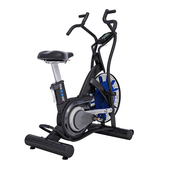
- Page 1 AirBike 90PRO...
- Page 2 This publication may not be reproduced, stored in a retrieval system, or transmitted in whole or in part, in any form or by any means, electronic, mechanical, photocopying, recording, or otherwise without the prior written permission of Maxxus Group GmbH & Co. KG.
-
Page 3: Safety Instructions
Safety Instructions Before you start exercising, be sure to read the entire operating manual, especially the Safety Information, the Maintenance and Clean- ing Information and the Training Information. Also make sure that anyone else who uses this training device is familiar with this informa- tion and observes it. - Page 4 Overview of the Device & Scope of Delivery Handlebars Cockpit Foot Rest Seat Transport Handle Pedal Stabiliser with Transport Rollers Stabiliser Description Description Lock nut M8 Allen screw M10x20 Allen screw M8x30 Allen screw M6x10 Pan head screw M5x12 Corrugated washer M10 Allen screw M6x15...
- Page 5 Overview of the Device & Scope of Delivery 51 (L) / 58 (R) 38 (L) / 39 (R) Description Qty. Description Qty. Base Frame Mounting plate Stabiliser, front 38 (L) Pedal, left Stabiliser, rear 39 (R) Pedal, right 51 (L) Handle, left Foot rest 58 (R)
- Page 6 Assembly Carefully unpack all parts of the delivery. Two people are required because some parts of your exercise ma- chine are bulky and heavy. Before mounting, check the completeness of the assembling hardware (screws, nuts, etc.) and the components in the parts and fastening materials list on the previous pages of this manual. Carefully carry out the installation, as damage or defects that have arisen due to assembly errors are not covered by the warranty under any circumstances.
- Page 7 Assembly Step 2: Assembling the Front Stabiliser Loosen and remove the transport lock on the front mount of the base frame (1) and then remove the transport lock. Then attach the front stabiliser (40) using four Allen screws M10x20 (108) and four corrugated washers M10 (112) to the front mount of the base frame (1).
-
Page 8: Step 4: Assembling The Handlebars
Assembly Step 4: Assembling the Handlebars Step 4.1 Insert the right handle (58) into the right axle of the base frame (1). Then push the footrest (83) onto the axle of the base frame (1) and tighten it clockwise with the special spanner –... - Page 9 Assembly Step 5: Assembling the Cockpit Frame Connect the cable (85B) protruding from the cockpit frame (48) to the cable (85C) protruding from the base frame (1). Then push the rest of the protruding cable back into the base frame (1) and then secure the cockpit frame (48) to the base frame using two Allen screws M8x30 (105).
-
Page 10: Saddle Adjustment
Saddle Adjustment Horizontal Adjustment You can adjust your saddle horizontally to set your optimum distance to the handlebars. Loosen the hand lever (B37) below the saddle by turning it anti-clockwise. Move the saddle to the desired horizontal position and retighten the hand lever clockwise. Hand Lever Vertical Adjustment You can adjust the saddle position vertically, i.e. -
Page 11: Care, Cleaning & Maintenance
Transport, Location & Storage Transport In order to transport your training device simply and safely, the front stand is equipped with transport rollers. To move the exerciser, stand behind the device and grab the transport handle with both hands. Lift the training device until the main weight of the device is resting on the front transport rollers. - Page 12 Cockpit Switching on the Cockpit Switch on the cockpit by pressing any button on the cockpit or by starting to pedal. Switching off the Cockpit Depending on the selected program, the cockpit switches off automatically after 60 to 90 seconds of inactivity. Inserting the Batteries The cockpit of your training device is powered by two AA 1.5V batteries.
- Page 13 Cockpit The cockpit continuously informs about the following, current training values: TIME - Indication of the training time. If the training time is set, the computer counts down the time to “00:00”. The The training time can be set from “01:00” to “1:59:00” minutes. If the training time is not set, the computer counts the training time from “00:00”...
-
Page 14: Quick Start
Cockpit TARGET CALORIES - Training program with target: calorie consumption TARGET HEART-RATE - training program with target: heart rate Note: An optionally available transmitter chest belt is required to use this program. Interval 10/20 - interval training with time change 10 seconds / 20 seconds Interval 20/10 - interval training with time change 20 seconds / 10 seconds Interval Custom - individual interval training Quick Start... - Page 15 Cockpit Training programme with target time (Target Distance) Step 1 – Program Selection Press the Target Distance program key. Step 2 - Target Time The time “0:0” will flash in the display. Now enter the desired training time from 0,5 to 999,5 by pressing the keys.
-
Page 16: General Functions
Cockpit Individual Interval Training (Interval Custom) This program allows the user to create their own individual interval training. Tip: Warm up at least 10 minutes before using this program for example with the Target Time or Quick Start pro- gram. After interval training, you should also have a recovery phase of 10 minutes at a low intensity, using either the Target Time or Quick Start program. - Page 17 Cockpit Current User Heart Rate If the “up” arrow is flashing, the heart rate is too low Changing display of 65 If the “down” arrow is flash- and 85% of the calculated ing, the heart rate is too high target heart rate Training End To end training, press the STOP key.
-
Page 18: Pulse & Heart Rate
Pulse & Heart Rate 100% of maximum heart rate of maximum heart rate of maximum heart rate of maximum heart rate Calculating your personal heart rate when training Calculate your personal heart rate when training as follows: 220 - Age = maximum heart rate This value represents your maximum heart rate and serves as a basis from which to calculate your personal training heart rate. - Page 19 Using a chest belt (we recommend the exclusive use of an uncoded POLAR® chest belt) allows you to wireless- ly measure heart rate. The chest belt is available online as an accessory from www.maxxus.com. This optimal, ECG-accurate type of measurement takes the heart rate by means of a transmitter chest belt directly from the skin.
-
Page 20: Training Recommendations
Training Recommendations Preparation Before Training Before you start training make sure that not only your training device is in perfect condition, your body must also be prepared for training. Therefore, if you have not done any endurance training for some time, you should con- sult your GP and undergo a fitness check-up. - Page 21 Training Recommendations Hydration Adequate hydration is essential before and during exercise. During a training session of 30 minutes it is possible to lose up to 1 litre of liquid. To compensate for this fluid loss apple spritzer mixed in the ratio of one-third apple juice to two-thirds mineral water is ideal since it contains electrolytes and minerals to replace those that the body loses through sweat.
-
Page 22: Technical Details
MAXXUS® Special Foam Cleaner Use for regular cleaning of your training device. Plastic covers and metal frames can be easily cleaned and perfectly maintained with MAXXUS ® Special Foam Cleaner. It is also suitable for cleaning pulse belts and other training accessories. - Page 23 My training device makes noises during training – is this normal? Your MAXXUS® training device is equipped with high-quality ball-bearings and a grooved belt. In addition, it also has a high-quality magnetic braking system which is completely wear and friction free. All these extremely high-quality components ensure that all functional noises are very much reduced.
-
Page 24: Exploded Drawing
Exploded Drawing... -
Page 25: Spare Parts List
Spare Parts List Part No. Description Part No. Description Main Frame Pressure Plate Fan Hub Pressure spring Pressure bushing Fan Hub Spacer Compression Block Fan Hub Sleeve Left hollow plug Fan Shaft Right hollow plug Bearing (6301Z) End cap Bearing (6901Z) Footrest Left Fan Cage Decorative Plug... - Page 26 Spare Parts List Part No. Description Part No. Description Bearing (6202Z) 100A Screw, Round Head (ST4x45) Bearing (6203Z) Screw, Round Head (ST4x15) C Ring (S40 mm) Bolt, Button Head (M8x40) Round Plug (Ø38 mm) Acorn Nut (M8 x 1.25) Right Handlebar Screw, Round Head (M5x8) Sensor Wire Bolt, Flat Socket Head (M8x30)
- Page 27 Notes...
- Page 28 Notes...
- Page 29 Notes...
-
Page 30: Terms And Conditions Of Warranty
The warranty period for your training device starts on the date of purchase and applies solely to products which were purchased directly from the MAXXUS Group GmbH & Co KG or one of the MAXXUS Group GmbH & Co KG direct and authorised distribution partners. -
Page 31: Service Contract
I accept the General Terms and Conditions of MAXXUS® Group GmbH & Co. KG. I hereby instruct the company MAXXUS® Group GmbH & Co. KG to repair the above defects. In Warranty cases I will not be charged for the cost. The costs for repairs which are excluded from liability for defects in quality will be charged to me and must be settled immediately. - Page 32 Maxxus Group GmbH & Co. KG Nordring 80 D-64521 Groß-Gerau Germany E-Mail: info@maxxus.de www.maxxus.com...
Need help?
Do you have a question about the AirBike 90PRO and is the answer not in the manual?
Questions and answers