Table of Contents
Advertisement
Quick Links
Advertisement
Table of Contents

Related Manuals for Eaton XC-152 Series


Summary of Contents for Eaton XC-152 Series
- Page 1 Manual 05/17 MN050001ZU EN XC-152 Compact Controller...
- Page 2 No part of this manual may be reproduced, stored in a retrieval system, or transmit- ted in any form or by any means, electronic, mechanical, photocopying, micro-film- ing, recording or otherwise, without the prior written permission of Eaton Industries GmbH, Bonn.
- Page 3 Danger! Dangerous electrical voltage! Before commencing the installation • Disconnect the power supply of the device. • Ensure a reliable electrical isolation of the low voltage for the 24 volt supply. Only use power supply units complying • Ensure that devices cannot be accidentally restarted. with IEC 60364-4-41 (VDE 0100 Part 410) or HD 384.4.41 S2.
-
Page 5: Table Of Contents
Safety regulations..............17 Basics................... 17 Mandatory requirements, personnel requirements ..... 17 2.2.1 Occupational safety..............17 2.2.2 Personnel qualifications ............... 18 2.2.3 Device documentation ..............18 2.2.4 Prerequisites for proper operation ..........18 Device-specific hazards..............19 Compact PLC XC-152 05/17 MN050001ZU DE www.eaton.com... - Page 6 CAN ..................... 53 5.4.4 Profibus..................55 XC-152 as a SmartWire-DT coordinator ........59 SmartWire-DT operator control and display elements ....59 6.1.1 POW/AUX SWD power supply ............ 60 6.1.2 SWD master interface ..............62 Compact PLC XC-152 05/17 MN050001ZU DE www.eaton.com...
- Page 7 Interfaces ..................74 SmartWire-DT Master ..............76 9.5.1 POW/AUX (power supply interface for SmartWire-DT)....76 9.5.2 SWD (SmartWire-DT interface) ............ 77 Approvals and declarations ............78 Applied standards and directives ..........78 Environmental conditions............. 79 Compact PLC XC-152 05/17 MN050001ZU DE www.eaton.com...
- Page 8 Compact PLC XC-152 05/17 MN050001ZU DE www.eaton.com...
-
Page 9: About This Manual
Installation requires qualified electrician 0.2 List of revisions The following table only lists major modifications. Publication Page Keyword Modifica- date tion 01/2013 New edition ✓ 12/2014 expansion ✓ 05/2017 Revision, Marine approvals, SWD ✓ ✓ Compact PLC XC-152 05/17 MN050001ZU EN www.eaton.com... -
Page 10: Documents With Additional Information
SWD- network in terms of hardware and software. SWD-Assist is available for download free of charge at Eaton's website. The aforementioned documents, as well as the manual you are reading right now, can also be downloaded free of charge in PDF format at: http://www.eaton.eu/doc... -
Page 11: Reading Conventions
Warns of the possibility of hazardous situations that could result in serious injury or even death. DANGER Warns of hazardous situations that result in serious injury or death. 0.4.3 Tips → Indicates useful tips. Compact PLC XC-152 05/17 MN050001ZU EN www.eaton.com... - Page 12 0 About this manual 0.4 Reading conventions Compact PLC XC-152 05/17 MN050001ZU EN www.eaton.com...
-
Page 13: Description
• Communication interfaces USB (USB device 2.0, USB host 2.0) 10/100 Mbps Ethernet port 1.1.2 Options Additional communication interfaces depending on the specific model: • SmartWire-DT, RS232, RS485, PROFIBUS/MPI, and CAN Compact PLC XC-152 05/17 MN050001ZU EN www.eaton.com... -
Page 14: Swd Coordinator Special Feature
Eaton calls this concept Lean Automation, and uses it to provide users in the machine building and plant engineering industries with unparalleled freedom so that they can design creative and profitable solutions. -
Page 15: Part Numbers
✓ ✓ ✓ ✓ XC-152-E6-11 167851 ✓ ✓ ✓ ✓ ✓ ✓ ✓ XC-152-E8-11 167852 ✓ ✓ ✓ ✓ ✓ ✓ ✓ XC-152-D6-11 167855 ✓ ✓ ✓ ✓ ✓ ✓ ✓ XC-152-D8-11 167849 Compact PLC XC-152 05/17 MN050001ZU EN www.eaton.com... -
Page 16: Operator Control And Display Elements
This LED is used to indicate various device and software statuses → Page 65 COM-LED Lights up green when data is being transmitted via the CAN or Profibus interface. Other LED states → Page 65 Compact PLC XC-152 05/17 MN050001ZU EN www.eaton.com... -
Page 17: Service Side
If the operating system on the memory card is invalid or is not found there to begin with (COM LED flashing red or orange), the CTRL button can be pressed in order to boot up with the internal operating system. Compact PLC XC-152 05/17 MN050001ZU EN www.eaton.com... -
Page 18: Accessory Devices
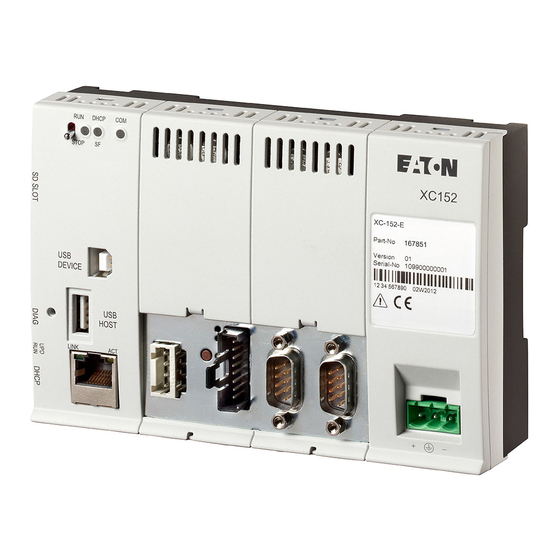
SD memory card with min. 256 MByte without operating system NOTICE Only use original accessories. Order accessories through your supplier or through the Eaton online catalog www.eaton.eu/ecat 1.8 Nameplate The device has a nameplate on rear. This nameplate makes it possible to identify the device and includes the following information: •... -
Page 19: Support
1.9 Support 1.9 Support In the unlikely event that you run into a problem with your device, please contact your local sales office or Eaton After-Sales Service for service and warranty questions. When you call, please have the following information ready: The exact part No. -
Page 20: Marine Approvals
→ Section "3.2 Conditions for marine approval (DNV GL)”, page → Section "3.2.1 Radio interference suppression filter for the 24 V DC supply”, page 27 → Section "3.3.2 Screening the communication cables used”, page 30 Compact PLC XC-152 05/17 MN050001ZU EN www.eaton.com... -
Page 21: Safety Regulations
2.2 Mandatory requirements, personnel requirements 2.2.1 Occupational safety All generally accepted occupational health and safety rules and standards (internal and national) must be complied with, as must be all applicable laws and regulations in the relevant country. Compact PLC XC-152 05/17 MN050001ZU EN www.eaton.com... -
Page 22: Personnel Qualifications
Additional parts of the documentation and information, including the installa- tion instructions, can be found at the Eaton Download Center - Documenta- tion and at the product pages on the Internet. http://www.eaton.eu/doc... -
Page 23: Device-Specific Hazards
The power transformer must meet all applicable standards. CAUTION DESTRUCTION The device should only be opened by the manufacturer or by an authorized repair center. Operate the device until only with the enclosure fully closed and sealed. Compact PLC XC-152 05/17 MN050001ZU EN www.eaton.com... - Page 24 Before putting the system into operation, check all cable con- nections to make sure that everything has been wired properly. Make sure that all voltages and signals have the required values as specified in the technical data. Compact PLC XC-152 05/17 MN050001ZU EN www.eaton.com...
- Page 25 ▶ Remove the SD card only when the device is de-energized. ▶ Before switching off the device, make sure that there are no programs writing to the SD card. Compact PLC XC-152 05/17 MN050001ZU EN www.eaton.com...
- Page 26 USB port), it is important to keep in mind that their EMC interference immunity parameters may render them unsuitable for use in industrial environments. The USB ports (USB host and USB device) on the device unit are meant for maintenance work only. Compact PLC XC-152 05/17 MN050001ZU EN www.eaton.com...
- Page 27 CAUTION Installation requires qualified electrician. NOTICE Arrange for an electrician to put together the cables for the power supply and the external connectors. Compact PLC XC-152 05/17 MN050001ZU EN www.eaton.com...
- Page 28 2 Safety regulations 2.3 Device-specific hazards Compact PLC XC-152 05/17 MN050001ZU EN www.eaton.com...
-
Page 29: Installation
▶ Do not let the device overheat. ▶ Do not expose the device to direct sunlight or other sources of heat. The environmental ambient conditions for operation must not exceed the specified values. Compact PLC XC-152 05/17 MN050001ZU EN www.eaton.com... -
Page 30: Conditions For Marine Approval (Dnv Gl)
The following DNV GL rules for shipping classification in accordance with DNVGL-CG-0339 type approvals must be observed: Complete and proper installation and commissioning in accordance with DNV GL rules and Eaton requirements and specifications. Installation of radio interference suppression filters for the 24 V DC sup- ply. -
Page 31: Radio Interference Suppression Filter For The 24 V Dc Supply
Depending on the output, the following filters can be used: • XT-FIL-1 radio interference suppression filter for 24 V DC supply up to 2.2 A (Eaton article no. 285316) or • XT-FIL-2 radio interference suppression filter for 24 V DC supply up to 12 A (Eaton article no. -
Page 32: Communication Cables
The cables being used must be assembled and terminated as required by the port/interface description in this document. When wiring the devices, follow all instructions regarding how to wire the corresponding port/interface. All general Directives and standards must be complied with. Compact PLC XC-152 05/17 MN050001ZU EN www.eaton.com... -
Page 33: Preparing The Cables With The Sub-D Plug
The folded screen braid end must be covered by the heat-shrink tub- ing or the rubber grommet ③. ▶4. Fit the SUB-D plug to the cable end: • The exposed metal screen braid must be clamped to the connector casing with the cable clamp. Compact PLC XC-152 05/17 MN050001ZU EN www.eaton.com... -
Page 34: Screening The Communication Cables Used
(max. distance of 20 cm from the external device plug) on the device. Screening with Figure 6: Figure 7: Ethernet cable shielding example: snap-together ferrite ring double loop through ferrite core Compact PLC XC-152 05/17 MN050001ZU EN www.eaton.com... -
Page 35: Unpacking And Checking The Equipment Supplied
The device should only be transported in its original packaging after being packed properly. Missing parts or damage If you notice anything wrong, please contact your distributor or Eaton Ser- vice: 24-hour hotline: +49 (0) 180 5 223 822 e-mail: AfterSalesEGBonn@Eaton.com... -
Page 36: Mounting
▶2. Check the device for transit damage. ▶3. Choose a device installation location based on your specific engineering documents. ▶4. Mount the device: • On a DIN-rail or • With additional fixing tabs Compact PLC XC-152 05/17 MN050001ZU EN www.eaton.com... -
Page 37: Din-Rail Mounting
Mounting on top-hat rail Figure 10: Dismantling 3.5.1.2 Dismantling ▶1. Use a flat screwdriver to pull the two locking sliders downwards until they lock into place. ▶2. Remove the device from the DIN-rail. Compact PLC XC-152 05/17 MN050001ZU EN www.eaton.com... -
Page 38: Screw Fixing
3.5 Mounting 3.5.2 Screw fixing → Use genuine Eaton accessories for the Compact PLC XC-152. ZB4-101-GF1 (Eaton article No. 061360) ▶1. Insert a tab into each of the fixing points at the back of the XC-152. You will need a total of four tabs. -
Page 39: Preparing The Device For Operation
Before commissioning, connect the device as required for your application: ▶1. Electrical connection 24 VDC power supply and, if applicable, SmartWire-DT network POW/AUX power supply ▶2. Connect the cables for the external connectors. ▶3. If applicable, shield the communication cables. Compact PLC XC-152 05/17 MN050001ZU EN www.eaton.com... -
Page 40: Power Supply 24 V Dc
Screw terminal plug-in Cross section min. 0.75 mm / max. 2.5 mm (drain wire or conductor) min. AWG18 / max. AWG12 Strip length 7 mm Max. tightening torque 0.6…0.8 Nm / 5…7 Lb. In. Compact PLC XC-152 05/17 MN050001ZU EN www.eaton.com... - Page 41 The device does not have an ON/OFF switch. If the power supply is not provided with a switch, the device will start up (boot) as soon as it is connected to the power supply. Compact PLC XC-152 05/17 MN050001ZU EN www.eaton.com...
- Page 42 3 Installation 3.6 Preparing the device for operation Compact PLC XC-152 05/17 MN050001ZU EN www.eaton.com...
-
Page 43: Commissioning
(boot) as soon as it is connected to the power supply. ▶ Apply the supply voltage to the device. The device will boot. → The runtime software for the PLC is installed on the device. Compact PLC XC-152 05/17 MN050001ZU EN www.eaton.com... -
Page 44: Initial Commissioning
Please also note that Remote-Client must be whitelisted if a firewall program is being used. Once access to the XC-152 is established for the first time, configure the XC- 152 with the computer. Compact PLC XC-152 05/17 MN050001ZU EN www.eaton.com... -
Page 45: Connect Computer And Xc-152 In The Network
SD card reader on computer. You will need to create two files and save them in the SD card's root direc- tory. “autolaunch.inf” file with the following contents: [autolaunch] open = SetIpAddress.bat RunOnBoot = 1 Compact PLC XC-152 05/17 MN050001ZU EN www.eaton.com... -
Page 46: Running The Xc-152
Operating states Operating system running: Operating system started in detect mode: → If the device will not start, or if the LEDs are signaling an error message, follow the instructions in the "Faults" section. Compact PLC XC-152 05/17 MN050001ZU EN www.eaton.com... -
Page 47: External Memory
4.3.1 Inserting and removing the SD card The slot for the SD card is on the side of the device. → An SD card is not included. Use genuine Eaton accessories for the Compact PLC XC-152. CAUTION DATA LOSS... - Page 48 Push the SD card in the MEM CARD slot all the way in. This will release the lock mechanism, and the SD card will come out of the SD slot a little. ▶ Remove the SD card from the MEM CARD slot. Compact PLC XC-152 05/17 MN050001ZU EN www.eaton.com...
-
Page 49: External Connections
The device may be damaged by potential differences. ▶ The GND terminals of all bus modules must be connected. ▶ Do not connect the connector to the device or disconnect it without first de-energizing the system. Compact PLC XC-152 05/17 MN050001ZU EN www.eaton.com... -
Page 50: Layout Overview
CANopen®/easyNet, not galvanically isolated, → Page 53 PROFIBUS/MPI max. 1.5 MBit/s, not galvanically isolated, → Page 55 not galvanically isolated G SmartWire-DT Master → Section "6 XC-152 as a SmartWire-DT coordinator”, page 59 Compact PLC XC-152 05/17 MN050001ZU EN www.eaton.com... -
Page 51: Usb Interfaces
Characteristics: USB 2.0, not galvanically isolated, plug type A, full power (500 mA) Figure 16: USB host interface (type A) 5.2.2.1 USB cable • Use only shielded standard USB cables. • Maximum cable length: 5 m. Compact PLC XC-152 05/17 MN050001ZU EN www.eaton.com... -
Page 52: Ethernet
Protect the RJ45 plug-in connection from strong vibrations. • Protect the RJ45 plug-in connection from tensile forces at the socket. To commission the communication between the XC-152 and the device, fol- low the description for the connected device. Compact PLC XC-152 05/17 MN050001ZU EN www.eaton.com... -
Page 53: Serial Interfaces To Other Devices
Arrange for an electrician to put together the cables for the power supply and the external connectors. → When preparing connections, ensure that the cable shield has a low impedance connection with the connector housing. Compact PLC XC-152 05/17 MN050001ZU EN www.eaton.com... -
Page 54: Rs232 (System Port)
The maximum baud rate (Baud rate) will depend on the cable length. RS232 cable length based on baud rate Cable length Possible baud rate 2.5 m 115200 bit/s 57600 Bit/s 10 m 38400 Bit/s 15 m 19200 Bit/s 30 m 9600 Bit/s Compact PLC XC-152 05/17 MN050001ZU EN www.eaton.com... -
Page 55: Rs485
9600 Bit/s 19200 Bit/s 38400 Bit/s 57600 Bit/s 115200 bit/s RS485 cable length based on baud rate Cable length Possible baud rate max 1200m 9600 Bit/s 19200 Bit/s 38400 Bit/s 57600 Bit/s 115200 bit/s Compact PLC XC-152 05/17 MN050001ZU EN www.eaton.com... - Page 56 450 - 650 Ω PIN 7, A A, + 120 Ω PIN 3, B B, - 450 - 650 Ω PIN 5, GND Figure 17: Bus termination RS485 Modbus Bus segment with four nodes Figure 18: Compact PLC XC-152 05/17 MN050001ZU EN www.eaton.com...
-
Page 57: Can
Permissible surge impedance Capacitance per unit length < 60 pF/m 0.25 mm Core cross- With a max. cable length of 100 m section 0.34 mm 250 m 0.75 mm 500 m Compact PLC XC-152 05/17 MN050001ZU EN www.eaton.com... - Page 58 The bus segment must be terminated at both ends. No more than two terminations must be provided for each bus segment. Operation without correct cable termination can cause transmis- sion errors. Figure 19: CAN bus segment with four nodes Compact PLC XC-152 05/17 MN050001ZU EN www.eaton.com...
-
Page 59: Profibus
EIA RS 485 cable A n.c. not used → • PIN 6 (5 V) must not be used as a power supply for external devices. • nc: PINs 1, 2, 7 and 9 must not be connected. Compact PLC XC-152 05/17 MN050001ZU EN www.eaton.com... - Page 60 Profibus MPI - relationship between cable length / baud rate Cable length Possible baud rate 100 m 1000 kbit/s 200 m 1500 kbit/s 400 m 500 kbit/s 1000 m 187.5 kbit/s 93.75 kbit/s 1200 m Compact PLC XC-152 05/17 MN050001ZU EN www.eaton.com...
- Page 61 No more than two terminations must be provided for each bus segment. At least one of the two terminations must be fed by the bus user. Operation without correct termination of the Profibus network can cause transmission errors. Compact PLC XC-152 05/17 MN050001ZU EN www.eaton.com...
- Page 62 5 External connections 5.4 Serial interfaces to other devices Compact PLC XC-152 05/17 MN050001ZU EN www.eaton.com...
-
Page 63: Xc-152 As A Smartwire-Dt Coordinator
U 6.1 SmartWire-DT operator control and display elements ⑤ ⑥ ① ⑦ ② ⑧ ③ ⑨ ④ power supply connection SWD- master interface SWD network SWD ribbon cable connection Figure 21: SmartWire-DT connectors Compact PLC XC-152 05/17 MN050001ZU EN www.eaton.com... -
Page 64: Pow/Aux Swd Power Supply
CSA-22.2, No. 14) are connected, an EU5C-SWD-PF1 or EU5C-SWD-PF2 power feeder module needs to be used. → If SmartWire-DT modules with a total current draw > 0.7 A are connected, an EU5C-SWD-PF2-1 power feeder module needs to be used. Compact PLC XC-152 05/17 MN050001ZU EN www.eaton.com... - Page 65 Observe the following when putting together the wiring for the plug connec- tor: Plug connector wiring Description/Value Terminal type: spring-cage terminal Cross section 0.2 - 1.5 mm (connectable conductor, solid) AWG24 - AWG16 Strip length 6 -7 mm Compact PLC XC-152 05/17 MN050001ZU EN www.eaton.com...
-
Page 66: Swd Master Interface
Switching on the device for initial commissioning, • Replacing SWD modules, or • Using a modified SWD configuration ▶1. Switch off the power supply. • All SmartWire-DT modules must be connected to each other via Smart- Wire-DT cables. Compact PLC XC-152 05/17 MN050001ZU EN www.eaton.com... - Page 67 ▶4. Load the PLC project (XSoft-CODESYS) onto the XC-152. • If the project configuration is identical to the stored target configuration, the Config LED lights up green and the data exchange of the input and output data can start. Compact PLC XC-152 05/17 MN050001ZU EN www.eaton.com...
- Page 68 The description of the project configuration (SmartWire-DT con- figuration in XSoft-CODESYS project) can be found in the Smart- Wire-DT configuration chapter in the relevant user manual → Section "0.3 Documents with additional information”, page 6 Compact PLC XC-152 05/17 MN050001ZU EN www.eaton.com...
-
Page 69: Malfunctions
CTRL button being pressed. Hardware fault Make sure that the jumper on the UPD/RUN pin header is not set to UPD. Servicing required: Please contact your supplier. Compact PLC XC-152 05/17 MN050001ZU EN www.eaton.com... - Page 70 If the UPD/RUN jumper is set to the RUN position, send in the device for repairs. Orange/green No PLC program present. Save PLC Program on device. flashing Orange PLC system error Check the PLC program Compact PLC XC-152 05/17 MN050001ZU EN www.eaton.com...
-
Page 71: Maintenance
10 years when de-energized, provided the corresponding ambient con- ditions are met and a temperature of 25 °C (77 °F) is maintained. The battery in the device is soldered and cannot be replaced. 8.2 Repairs For repairs, please contact your vendor or Eaton's Technical Support. CAUTION DESTRUCTION The device should only be opened by the manufacturer or by an authorized repair center. -
Page 72: Storage And Transport
Accordingly, make sure to protect the device from mechanical loads that exceed the scope of the unit's intended use. The device should only be transported in its original packaging after being packed properly. Compact PLC XC-152 05/17 MN050001ZU EN www.eaton.com... -
Page 73: Disposal
• Battery weight 3.7g • SVHC Substance 1.2-dimethoxyethane: ethylene glycol dimethyl ether (EGDME) • Substance weight 2-4 % Packaging Materials used External packaging Cardboard Inner packaging Cardboard with PE sheet Plastic bag: polyethylene (PE) Compact PLC XC-152 05/17 MN050001ZU EN www.eaton.com... - Page 74 8 Maintenance 8.4 Disposal Compact PLC XC-152 05/17 MN050001ZU EN www.eaton.com...
-
Page 75: Technical Data
30 mm (1,18“) Device without fixing brackets 41.5 mm (1,63“) 50.6 mm (1,99“) Device with fixing brackets 43 mm (1,69“) 52.1 mm (2,05“) Weight Approx. 0.3 kg (0,66 lbs) Approx. 0.3 kg (0,66 lbs) Compact PLC XC-152 05/17 MN050001ZU EN www.eaton.com... -
Page 76: System
(not for SDHC cards or cards of newer standard) RTC Real Time Clock yes, battery back-up Battery type Lithium CR 2032, maintenance-free (soldered) Battery (service life) Normally 10 years at 25° C (77°F) Compact PLC XC-152 05/17 MN050001ZU EN www.eaton.com... -
Page 77: Power Supply
Current consumption Continuous current Max. 0.35 A (24 VDC) Starting current inrush 1.5 A Protection against polarity reversal Yes fuse (replacement only by the manufacturer or by an authorized repair center) Potential isolation Compact PLC XC-152 05/17 MN050001ZU EN www.eaton.com... -
Page 78: Interfaces
Profile SMTP HTTP Baud rate 100Base-TX 10Base-T Potential isolation 500V Programming interface Connections RJ45 not galvanically isolated USB Host USB 2.0, (1.5/12/480 MBits) Potential isolation none USB device USB 2.0 Potential isolation none Compact PLC XC-152 05/17 MN050001ZU EN www.eaton.com... - Page 79 Profile CANopen®/ CANopen®/ easyNet easyNet (Master/Device) (Master/Device) Baud rate Max. 1000 kBit/s Max. 1000 kBit/s Potential isolation none none Number of users 9 pole Connections 9 pole SUB-D (plug) SUB-D (plug) Compact PLC XC-152 05/17 MN050001ZU EN www.eaton.com...
-
Page 80: Smartwire-Dt Master
1) If contactors and/or motor starters with a total current draw > 3 A (DIN VDE 0641, Part 11 and IEC/EN 60898) or > 2 A (UL 508 and CSA-22.2, No. 14) are connected, an EU5C-SWD-PF1 or EU5C-SWD-PF2 power feeder module needs to be used. Compact PLC XC-152 05/17 MN050001ZU EN www.eaton.com... -
Page 81: Swd (Smartwire-Dt Interface)
250 kBit/s (= default settings) Connections Blade terminal SWD4-8MF2 1) If SmartWire-DT modules with a total current draw > 0.7 A are connected, an EU5C-SWD-PF2-1 power feeder module needs to be used. Compact PLC XC-152 05/17 MN050001ZU EN www.eaton.com... -
Page 82: Approvals And Declarations
Programmable logic controllers: Equipment requirements and tests IEC/EN 60068-2-27 Mechanical shock resistance with 15 g / 11 ms IEC/EN 60068-2-31 Fall test IEC/EN 60068-2-6 Vibration Displacement: 5 to 8.4 Hz: 3.5 mm; Acceleration: 8.4 to 150 Hz: 1 g Compact PLC XC-152 05/17 MN050001ZU EN www.eaton.com... -
Page 83: Environmental Conditions
± 0 – +55 °C operation ± 0 – +50 °C (+32 – +122 °F) Storage / Transport -20 – + 60 °C (-4 – +140 °F) Humidity/Condensation Relative humidity 10 - 95 % non-condensing Compact PLC XC-152 05/17 MN050001ZU EN www.eaton.com... - Page 84 9 Technical data 9.8 Environmental conditions Compact PLC XC-152 05/17 MN050001ZU EN www.eaton.com...
- Page 85 ........56 Compact PLC XC-152 05/17 MN050001ZU EN www.eaton.com...
- Page 86 Eaton’s Electrical Sector is a worldwide leader in power dis- Eaton Adressen weltweit: tribution, uninterruptible power supplies, switches, contac- www.eaton.com tors, and automation and visualization of industrial pro- cesses. The combination of a broad product range and our engineering services enables us to supply energy manage- E-Mail: info-bonn@eaton.com...
Need help?
Do you have a question about the XC-152 Series and is the answer not in the manual?
Questions and answers