Table of Contents
Advertisement
Quick Links
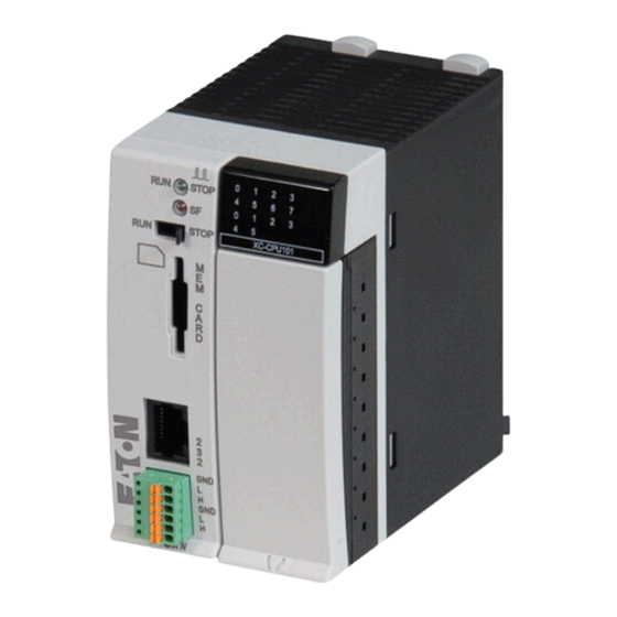
PATRZ KARTA - XC-CPU101-C64K-8DI-6DO
Modułowy sterownik PLC, 24VDC, 8WEC, 6WYC, RS232, CAN, 64kB
Typ
Catalog No.
Eaton Catalog No.
Program dostaw
Liczba wejść cyfrowych
Liczba wyjść
Wbudowane interfejsy
Wskazówki
Pamięć użytkowa
Czas cyklu do instrukcji 1 k (Bit, Byte)
Pamięć
Zastosowanie/Znaczniki/Przechowywane dane
Zintegrowany serwer WWW
Informacja o zakresie dostawy
Dane Techniczne
Dane ogólne
Normy i przepisy
Temperatura otoczenia
Przechowywanie
Położenie montażowe
Względna wilgotność powietrza, bez obroszenia (IEC/EN 60068-2-30)
Sprężone powietrze (praca)
Wytrzymałość zmęczeniowa
Wytrymałość udarowa mechaniczna
Kategoria przepięciowa / stopień zanieczyszczenia
Stopień ochrony
Znamionowe napięcie izolacji
Emisja zakłóceń
Odporność na zakłócenia
Bateria (trwałość)
Ciężar
Zaciski
Przekrój doprowadzeń
Zaciski śrubowe
Linka z tulejką
przewód pojedynczy
Zaciski sprężynowe
Linka z tulejką
przewód pojedynczy
Zasilanie
Czas wejścia do sieci
Szybkość powtarzania
Napięcie wejściowe
zakres dopuszczalny
Moc na wejściu
28.02.2018
XC-CPU101-C64K-8DI-6DO
262152
XC-CPU101-C64K
ms
°C
ϑ
°C
%
hPa
g
U
V
i
kg
mm²
2
mm
2
mm
2
mm
2
mm
ms
s
napięcie
stałe, V
V DC
W
Eaton 262152 ED2018 V41.0 PL
Cyfrowe: 8; z czego wykorzystywane jako przerwanie: 4
Tranzystor: 6
CANopen®/easyNet
RS232
rozszerzalne z → rozszerzenia XI/OC
tylko w połączeniu z → podstawą magistralną XI/OC
64 kByte
0.5
64 KB/4 KB/4 KB
nie
Potrzebne są następujące akcesoria: zaciski przyłączeniowe, podstawa
magistralna, bateria
IEC/EN 61131-2
EN 50178
0 - +55
-25 - +70
poziomo
10 - 95
795 - 1080
10 - 57 Hz ±0,075 mm
57 - 150 Hz ±1,0 g
15
Czas udaru 11 ms
II/2
IP20
500
EN 50081-2, klasa A
EN 50082-2
zwykle 5 lat
0.23
wtykany blok zacisków
0,5 - 1,5
0,5 - 2,5
0,34 - 1,0
0,14 - 1,0
10
1
24
20.4 - 28.8
maks. 26
1 / 6
Advertisement
Table of Contents


Need help?
Do you have a question about the XC-CPU101 Series and is the answer not in the manual?
Questions and answers