Table of Contents
Advertisement
Advertisement
Table of Contents

Subscribe to Our Youtube Channel
Related Manuals for Dräger REGARD 7000


Summary of Contents for Dräger REGARD 7000
- Page 1 Instructions for use REGARD 7000...
- Page 2 This page has been left blank intentionally.
-
Page 3: Table Of Contents
Conventions in this document Meaning of the warning notes Typographical conventions Brands System overview System description Safety design REGARD 7000 components Intended Use Limitations on use Approvals Marking Approvals granted Approved components for functional safety and measuring function for flammable gases, oxygen and toxic gases... - Page 4 Prerequisites for plants in the area of functional safety and measurement function for flammable gases, oxygen and toxic gases Prerequisites for plants conforming to NFPA 72 Requirements for plants in the maritime sector Special features of operation of the REGARD 7000 in combination with a REGARD System behaviour...
- Page 5 Contents User role concept View only role Operation role Maintenance role Configuration role Administration role View role During operation Operation role During operation Maintenance role Docking Station maintenance Maintenance of modules Maintenance of channels and ports Dashboard settings Configuration role General configuration procedure Export configuration and reports Save or import configurations...
- Page 6 Contents REGARD 7000 configuration software Introduction Contents of these help pages Setting up an account Operating concept for the software Program interface Editing configuration settings Software operating modes Offline configuration mode Online configuration mode Creating a new system configuration Usable key combinations...
- Page 7 Contents Meaning of fields Assignment of the input register Channel types Structure of the state register of REGARD 7000 channels 153 Structure of alarm state information Structure of output state information Assignment of the holding register Diagnostics Information for Modbus RTU Master...
- Page 8 Safety-related information Safety-related information – Before using this product, carefully read these instructions for use and those of the associated and connected products (e.g. transmitter, alarm device). – Strictly follow the instructions for use. The user must fully understand and strictly observe the instructions.
-
Page 9: Safety-Related Information
Conventions in this document Conventions in this document Meaning of the warning notes The following alert messages are used in this document to provide and highlight areas of the associated text that require a greater awareness by the user. A definition of the meaning of each alert message is as follows: Alert icon Signal word... -
Page 10: System Description
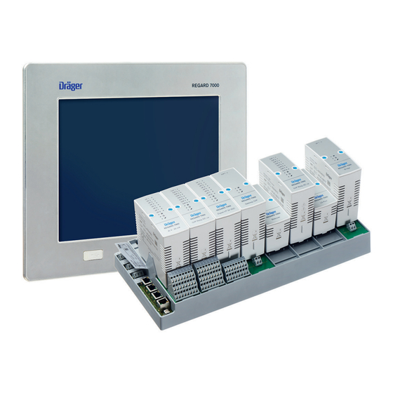
Input Output REGARD 7000 is a modular control unit for gas and fire alarm systems. The control units consist of one or more Docking Stations, each of which can contain up to 8 modules. The REGARD 7000 is a system with distributed intelligence. Each module has the intelligence required for its function. -
Page 11: System Overview
The system continuously monitors the correct function. Every system fault results in drop-out (normally energized) of the respective fault relay on the Docking Station. Systems with requirements as per SIL3 can be implemented with REGARD 7000 by using a structure with redundant channels. -
Page 12: Regard 7000 Components
REGARD 7000 is approved under IEC/EN 61508:2010 and EN 50402:2017 for SIL 2 applications or for SIL 3 with the corresponding plant setup. For details of the configuration and system layout for SIL 2 or SIL 3 see the Dräger REGARD 7000 Safety Manual (order no. 90 33 497). -
Page 13: Approvals Granted
– oxygen inertisation measurements under ATEX – oxygen and toxic gases REGARD 7000 is suitable for use in setting up gas and fire alarm systems in accordance with NFPA 72:2016. The Digital lnput modules types and all relay modules can be used for this purpose. The Digital Input module offers the monitoring function according to NFPA 72 Class B;... -
Page 14: Approved Components For Functional Safety And Measuring Function For Flammable Gases, Oxygen And Toxic Gases
System overview IEC/EN 61508-3:2010 Certificate: 968/FSP 1374.00/17 Maritime sector Inspection authority: DNV GL SE Standards: IEC 60533:2015 IEC 60945:2002+A1:2008 IEC 60092-504:2016 Certificate: MED B 00002Z6 (MED) TAA00001S9 (DNV) 3.6.3 Approved components for functional safety and measuring function for flammable gases, oxygen and toxic gases The following components have been tested and approved for operation in a safety or measuring function: Module... -
Page 15: Approved Components According To Nfpa 72
Docking Station 8-Slot Docking Station 4-Slot 3.6.5 Approved components for plants in the maritime sector System components Order number Software / REGARD 7000 Firmware version Docking Station 8-Slot 83 22 286 Docking Station 4-Slot 83 22 320 Advanced Dashboard 6RU 83 26 850 1.00.xx - 1.03.xx... -
Page 16: Accessories Relevant For Approval
Dräger ServiceConnect (https://www.serviceconnect.draeger.com) for a period of at least 3 years after purchase of the software as a supplement to the instructions for use. The access ® data for Dräger ServiceConnect is supplied with the REGARD 7000 dashboard. -
Page 17: System Components Docking Station
The Docking Station forms the basis assembly of the REGARD 7000 system. Up to 4 or up to 8 REGARD 7000 modules can be plugged into the Docking Station. The Docking Station manages the power supply of all its modules and via the modules it indirectly powers the associated transmitters (for transmitters with a max. -
Page 18: Docking Station 4-/8-Slot
System components Contact assignment for special state relay (SSR) In the inactive state the SSR is not operational (energized on alarm). If there is no special state, NC and Common are connected. Activation by a special state. 10 Contact assignment for fault relay (SFR) In the normal state the SFR is energized and operational (normally energized). -
Page 19: Technical Data Docking Station 4/8 Slots
I/P 6 I/P 6 I/P 7 I/P 7 I/P 8 I/P 8 REGARD 7000 REGARD 7000 AI 4 - 20 mA AI 4 - 20 mA/HART Input 1 to 8 and channel display Lights if a loop current is flowing. -
Page 20: Ma Input Module / Hart
Use of signal duplicators For the use of REGARD 7000 and one additional signal receiver, 4-20mA signal duplicators can be used. Dräger has qualified the following components for this purpose: Manufacturer Order no. - Page 21 (terminals 2.1 and 2.2 or 3.1 and 3.2). The connection is ® made on terminals x.2 and x.3 of REGARD 7000 Terminal Blocks. The HART communication between the transmitter and the module 4-20 mA Input HART is not affected by components qualified by Dräger.
- Page 22 System components Transmitter supply volt- Typically 24 V, depending on the supply voltage of the age: Docking Station. Transmitter supply cur- With assignment of max. 4 inputs: rent: Max. 500 mA per channel With assignment of 4 to 8 inputs: Max.
-
Page 23: Modbus Rtu Master Module
System components I/P 1 REGARD 7000 Modbus RTU Master Lights up green if there is communication with a Modbus RTU Slave. Does not light if there is no or only faulty communication. Fault display Lights if there is a module or channel error. - Page 24 I/P 4 I/P 5 I/P 6 I/P 7 I/P 8 REGARD 7000 Digital I/P 24 VDC Input 1 to 8 and channel display Lights if a loop current is flowing. Fault display Lights if there is a module or channel error.
-
Page 25: Digital Input Module
System components One or more buttons, switches, fire and/or smoke alarms can be connected and queried at a digital input. Closed current loop and alarm current can be freely configured in wide ranges per channel. The switching behaviour can be configured rising or falling. - Page 26 System components When dimensioning the resistors, the supply voltage of the REGARD 7000 System should be taken into account as neither the Docking Stations nor the modules perform 24 V voltage regulation. A change of the supply voltage has a linear effect on the currents.
- Page 27 System components Example of a falling application 2 (8 switches/buttons) = 90 mA Digital In + 2,4kΩ 2,4kΩ 2,4kΩ 2,4kΩ 2,4kΩ 2,4kΩ 2,4kΩ 2,4kΩ 0,5W 0,5W 0,5W 0,5W 0,5W 0,5W 0,5W 0,5W 240Ω Digital In - = ... = 10 mA = 100 mA Wire break current (0.5 x static current) Static current = total of all currents (I...
- Page 28 System components Example of rising application = 24 mA = 24 mA = 24 mA = 50 mA Digital In + 1kΩ 1kΩ 1kΩ 480Ω Digital In - Current threshold Wire break current (0.5 x static current = 25 mA) Static current Current states Switching behaviour depending on the current threshold...
- Page 29 O/P 2 O/P 3 O/P 4 O/P 5 O/P 6 O/P 7 O/P 8 REGARD 7000 O/P Relay DC Relay display Lights if current is flowing through the relay coil. Fault display Lights if there is a module or channel error.
-
Page 30: Relay Module 240 V Ac / 240 V Ac Complex
(e.g. a branch line from the building installation). Dräger recommends providing a shut-down option for the 240V AC lines on the relay module that is separate from the power supply to the REGARD 7000 power supply unit. -
Page 31: Relay Module 24 V Dc / 24 V Dc Complex
O/P 3 O/P 4 O/P 5 O/P 6 O/P 7 O/P 8 REGARD 7000 O/P Relay DC Relay display Lights if the relay coil is activated. Fault display Lights if there is a module or channel error. Lights when the module is under power. -
Page 32: Gateway Module
System components The Relay 24 V DC module is not approved for switching 240 V AC loads. 4.2.6 Gateway Module Gateway module for output of system data via a fieldbus-specific interface to higher level systems, such as to a DCS (Distributed Control System) or SCADA (Supervisory Control and Data Acquisition) system. - Page 33 07 06 05 04 03 02 01 01 02 03 04 05 06 07 Modbus RTU Gateway 07 06 05 04 03 02 01 High REGARD 7000 Gateway Profibus DP Gateway 07 06 05 04 03 02 01 Profinet Gateway...
- Page 34 System components Lights up green if there is valid communication with the fieldbus-specific gateway. Fault display Lights if there is a module or channel error. Lights when the module is under power. Data transfer display Flashes when the module is communicating. Power/State Lights when the module is under power.
- Page 35 In position 0 (zero), the PROFIBUS DP gateway adopts the slave ID that was configured via the REGARD 7000 configuration software. The other positions set the slave ID directly. In this situation, the slave ID that was configured via the REGARD 7000 configuration software is ignored.
- Page 36 1.5 MBd max. 200 m >1.5 MBd max. 100 m PROFINET Gateway: 100 m Terminal Block: 2-pin / 3-pin Galvanic isolation between REGARD 7000 and fieldbus-side via fieldbus-specific gateway 4.2.7 Long Distance Gateway Module for connecting spatially remote Docking Stations, comprising a Long Distance Gateway Port and 2 bidirectional Ethernet-to-DSL converters.
-
Page 37: Long Distance Gateway
If there are multiple wire breaks between the DSL converters in 2-wire operation, the fault LED on the converter lights. The transmission rate is reduced to 64 kB. This results in a communication error on the REGARD 7000. Remedy: Restart both DSL converters by disconnecting and reconnecting the DSL converter power supply. - Page 38 System components Galvanic isolation: Ethernet to DSL Max. wire length between 1200 m for 28 AWG line pair of converters: 1700 m for 25 AWG line 2150 m for 23 AWG line 3200 m for 21 AWG line 4000 m for 16 AWG line For connecting Docking Stations that are physically remote, an optical fibre connection (OF connection) can be used.
-
Page 39: Bridge Module
An existing REGARD with up to 99 channels can be integrated into the REGARD 7000 with the bridge module. More information: – "Compatible REGARD components" – "Special features of operation of the REGARD 7000 in combination with a REGARD" I/P 1... -
Page 40: Slot Cover
4.2.9 Slot cover Slot cover for assignment of unused slots in a docking station. REGARD 7000 Slotcover The docking station monitors the assignment of all module slots. Unused slots in a docking station must be assigned with a slot cover. An unassigned slot in a docking station will cause activation of the SFR. -
Page 41: Terminal Block 24 Pole Dc
System components 4.3.1 Terminal Block 24 pole DC Terminal Block for connecting input and output signals (24 V) to a 4-20 mA Input / HART or Relay 24 V DC module. 24 V 1.1 2.1 3.1 4.1 5.1 6.1 7.1 8.1 1.2 2.2 3.2 4.2 5.2 6.2 7.2 8.2 1.3 2.3 3.3 4.3 5.3 6.3 7.3 8.3 Connection plug to module... -
Page 42: Terminal Block 24 Pole Ac
System components 4.3.2 Terminal Block 24 pole AC Terminal Block for connecting the output signals to a Relay 240 V AC module. The Terminal Block 24 pole AC is supplied with a code plate to prevent accidental connection of an incorrect module. The code plate only fits the modules of the Relay 240 V AC type. -
Page 43: Terminal Block 16 Pole
System components 4.3.3 Terminal Block 16 pole Terminal Block for connection of input signals (24 V) to the Digital Input module. 24 V 1.1 2.1 3.1 4.1 5.1 6.1 7.1 8.1 1.2 2.2 3.2 4.2 5.2 6.2 7.2 8.2 Connection plug to module Slot for code plate for prevention of confusion of different module types. -
Page 44: Terminal Block 16 Pole Res
System components 4.3.4 Terminal Block 16 pole Res For applications of functional safety or measuring function for flammable gases, oxygen or toxic gases, the use of this Terminal Block is only permitted for inputs in Inhibit operating mode or acknowledgement. Terminal Block for connecting input signals (24 V) to the Digital Input module. -
Page 45: Terminal Block 2 Pole / 3 Pole
Terminal Block 2 pole / 3 pole The Terminal Block can be used for the following applications: – for connecting a REGARD 7000 via a bridge module to a REGARD ® – for connecting a gateway module to a UNIGATE... -
Page 46: Dashboard
Dashboard. 4.4.1 Add-on functionalities The operation of REGARD 7000 via a dashboard can be supplemented using licensable additional functions in the form of add-on licences. For further information, see the following chapter: "Display and install add-on licences", page 119... -
Page 47: Advanced Dashboard 6Ru
Dashboard with 30.7 cm (12.1 inch) screen diagonal for installation in a switch cabinet. Touchscreen for operation of the system and viewing data. REGARD 7000 Ports as on the Advanced Dashboard 6RU, also a USB port in the front panel. - Page 48 System components Technical data Operational voltage: 24 V (19.2 to 28.8 V) DC Power input: Typ. 0.7 A at 24 V DC...
-
Page 49: Installation & Commissioning
System structure REGARD 7000 forms the central control unit for the complete gas and, if applicable, fire alarm system. REGARD 7000 is designed for installation in a switch cabinet. The REGARD 7000 Docking Station is bolted to a corresponding mounting plate in the cabinet (see assembly instructions Docking Station). -
Page 50: System Limits
Installation & commissioning 5.2.1 System limits REGARD 7000 REGARD 7000 ..REGARD 7000 REGARD 7000 REGARD 7000 ..REGARD 7000 REGARD 7000 The following limits apply to a system: – Max. 24 docking stations – Max. 192 modules – Max. 16 dashboards –... -
Page 51: Prerequisites For The System Structure
Installation & commissioning 5.2.2 Prerequisites for the system structure – Plan the structure to ensure that the REGARD 7000 can be protected from unauthorised access. The system operator is responsible for access to the REGARD 7000. – Before handling electronic system components, make sure that the persons handling them are earthed to prevent damage to the components. -
Page 52: Additional Requirements For Plants With Measuring Function For Flammable Gases, Oxygen Or Toxic Gases
Additional requirements for plants with measuring function for flammable gases, oxygen or toxic gases – The REGARD 7000 system and the system components must be protected from unauthorised access (e.g. with a lockable switch cabinet). – The design of the system must also take into account the response times of all... -
Page 53: Assembly And Installation
(single errors). The design of a double ring structure covers a line break at any point in the corresponding ring (double errors). In both cases, the REGARD 7000 signals a communication error; the measuring function is retained. These structure variants have not been checked by the DEKRA EXAM. In plants conforming to PFG 16 G 006 X or BVS 16 ATEX G 003 X these structure variants are still permitted. -
Page 54: Commissioning
Configure module and send the configuration. The module is now linked to the new slot. An unconfigured module generates a fault when the system is started, which is deleted by a valid configuration. 5. Configure REGARD 7000 system with the Dashboard. Commissioning 5.3.1 Requirements for commissioning –... -
Page 55: Switching On Regard 7000
After switching on the REGARD 7000 system, different special states may be encountered depending on the system structure, system size and system configuration. They clear without intervention, but in some cases may be latching. -
Page 56: Control
5555 Operation To log in a user on a REGARD 7000 system with the Dashboard: 1. Select the desired user in the Select user dropdown list. 2. In the Enter password input field enter the password using the numeric pad and confirm with ... -
Page 57: Screen Structure (List View)
Control Screen structure (list view) Display selection list Progress bar Log user in or out List view/column view Navigation bar Menu bar Channel list Header bar User roles Icon Role Description View only Observe the information in the following chapter: "View role", page 76 Operation Observe the information in the following chapter:... -
Page 58: List And Column View
Control List and column view Two types of view can be selected for displaying the input and output channels. Icon Function Description List view Display list view (display of up to 10 channels). Column view Display column view (display of up to 40 chan- nels). -
Page 59: Navigation Buttons
Control The buttons for scrolling to the channels in alarm state are only displayed if there are channels in the alarm state. With the automatic scroll function activated, the channel display is automatically scrolled 60 s after the last operation, if more channels are present in the view than can be displayed on the dashboard. -
Page 60: Title Bar Of The Channel Display (List View)
Control Title bar of the channel display (list view) ID: ID of the displayed channel Tag: Name of the displayed channel. The name of the channel can be selected as desired during system configuration. Process values: Depending on the module type, various process information such as measured value, gas type and measurement unit or alarm, alarm type are displayed. -
Page 61: Buttons Of The Display Selection Bar
Control Icon Function Description Acknowledge- Select this button to acknowledge all acknowl- ment of all chan- edgeable events in the system. nels The "Acknowledgement of all channels" function acknowledges all undisplayed channels as necessary. Buttons of the display selection bar Icon Function Description... -
Page 62: Generally Used Icons
Control 6.11 Generally used icons Icon Description The channel is in the Inhibit state. This is used, for example, during a calibration to suppress activation of an alarm element in spite of a pending alarm condition. The channel remains in the Inhibit state for 321 seconds. Information is available on the channel. -
Page 63: Channel View Of The Module Types
Control Icon Description There is a complex configuration on the channel. The channel has a first alarm. The channel has an eighth alarm and there are additional alarms on the channel. 6.12 Channel view of the module types Icon Description 4-20 mA Input Module (Input) 4-20 mA Input Module / HART (Input) Digital Input Module (Input) -
Page 64: Icons In The Measured Value And Status Field Of The Channel Display With Relay Output Channels
Control Icon Description An over range, a second alarm, additional alarms and a warning are pending. Methane %LEL A first alarm, information and a communication error are pending. Methane %LEL The input channel remains in the inhibit state for Measurement value 321 s. -
Page 65: Icons In The Measured Value And Status Field Of The Channel Display With Modbus Output Channels
Control 6.15 Icons in the measured value and status field of the channel display with Modbus output channels Icon Description A Modbus communication is pending. Modbus PROFIBUS communication is present. PROFINET communication is present. 6.16 Icons in the measured value and status field of the channel display with bridge channels Icon Description... -
Page 66: Status Signalling With The Presentation Of Channel States
Control Icon Description Channel in warning state ▼ Channel has information If an alarm is issued before an error occurs on the channel, this condition will be frozen during the error. Once the error has been rectified, the alarm condition will be displayed again, and updated as appropriate. -
Page 67: Side Bar
Control 6.19 Side bar A side bar is displayed in the Port menu and in the Channel menu. This side bar can be used to switch between the Ports and channels. 6.20 Alarm confirmation modes The following graphic shows the output behaviour of a relay output depending on the configured alarm confirmation mode, a pending alarm and the acknowledgement signal. - Page 68 Control time time Acknowledgement is accepted. Acknowledgement not effective. Case descriptions LACK (latching and acknowledgeable) Case A Case B 1. Alarm condition triggered. 1. Alarm condition triggered. 2. Relay is activated. 2. Relay is activated. 3. Acknowledgement is actuated during 3.
- Page 69 Control LPAK (latching and pre-acknowledgeable) Case A Case B 1. Alarm condition triggered. 1. Alarm condition triggered. 2. Relay is activated. 2. Relay is activated. 3. Pre-acknowledgement is actuated 3. Alarm condition cleared, relay during the alarm condition, relay remains activated. remains activated.
-
Page 70: Operation
Measurement range minimum set to 0. – If a transmitter is used with a catalytic sensor, the Overrange latching function on the REGARD 7000 input channel or in the transmitter should be activated. For further information, see the following chapter: "Overrange acknowledge parameter menu", page 93. -
Page 71: Prerequisites For Plants Conforming To Nfpa
With multiple outputs for the highest alarm, deviations are permitted (e.g. for acoustic alarm devices). – Follow the REGARD 7000 Safety Manual (order no. 90 33 497) for a system in the field of functional safety. The REGARD 7000 Safety Manual can be ®... -
Page 72: Requirements For Plants In The Maritime Sector
2.5 s, i.e. the reaction time will be approx. 4 minutes for 99 channels. The following restrictions must be noted: – If an alarm in REGARD is acknowledged from REGARD 7000, the alarm state of the REGARD master card must be acknowledged separately at the master card. - Page 73 – In the case of a REGARD system, an over range of a REGARD channel is displayed in the REGARD 7000 with up to 20 s delay depending on the number of channels. The alarm triggering is not affected by this delay.
-
Page 74: System Behaviour
Operation... - Page 75 Operation...
-
Page 76: User Role Concept
Operation User role concept REGARD 7000 has a function and rights management oriented to user roles. Individual users can be created and must be assigned one of 5 roles. Corresponding higher-level functions and rights are available for selecting the role. -
Page 77: Administration Role
Danger of an inconsistent configuration display. After changing the channel tag or the channel ID of a channel, another dashboard/PC with REGARD 7000 configuration software can be used to display the channel tag and module type for this channel unchanged in the following views: –... -
Page 78: During Operation
Danger of an inconsistent configuration display. After changing the channel tag or the channel ID of a channel, another dashboard/PC with REGARD 7000 configuration software can be used to display the channel tag and module type for this channel unchanged in the following views: –... -
Page 79: Docking Station Maintenance
Danger of an inconsistent configuration display. After changing the channel tag or the channel ID of a channel, another dashboard/PC with REGARD 7000 configuration software can be used to display the channel tag and module type for this channel unchanged in the following views: –... - Page 80 6. Select the Test special state relay button and check whether the SSR is switched. Run the test of the SFR and SSR in SIL systems at regular intervals as directed in the REGARD 7000 Safety Manual and document the test.
-
Page 81: Maintenance Of Modules
Operation 7.10.2 Maintenance of modules Selecting the Docking Station displays the modules in the Docking Station. Proceed as follows to identify the module that is to be maintained: 1. Select the button in the channel list view. 2. Select the Docking Station in which the module is installed. 3. -
Page 82: Maintenance Of Channels And Ports
Operation 4. Select Module maintenance. 5. Select Restart. A wizard is opened. 6. Follow the directions of the wizard. 7.10.3 Maintenance of channels and ports The various functions for maintenance of a channel and Ports are described below. The functions are identical for channels and Ports. To display the configuration of a channel or Ports: ►... -
Page 83: Dashboard Settings
Operation 3. Activate the checkbox of the desired channel. 4. Select Set inhibit. All selected channels are locked. 7.10.3.2 Maintenance menu Relay proof test (relays only) To carry out a relay test: 1. Open Maintenance menu > Relay proof test. 2. -
Page 84: Configuration Role
Danger of an inconsistent configuration display. After changing the channel tag or the channel ID of a channel, another dashboard/PC with REGARD 7000 configuration software can be used to display the channel tag and module type for this channel unchanged in the following views: –... - Page 85 Operation 7.11.1.1 Open configuration mode CAUTION Danger of an inconsistent configuration All settings and system comparisons in configuration mode always relate to the imported system configuration when configuration mode is entered. Subsequent changes to transmitter configurations are not taken into account. ►...
-
Page 86: Export Configuration And Reports
7000 Advanced Dashboard that permits an overview of all components included in the gas warning system to be generated. All item and serial numbers of the REGARD 7000 components are currently exported and displayed in the report. Components that have been included in the configuration during the commissioning process are also listed. -
Page 87: Compare System Configuration (Optional)
– Component report or system documentation add-on licence installed. – System configuration file (.sev file) is available for the comparison. – When using the configuration software: REGARD 7000 is connected to the PC. – When using the configuration software: Configuration port is configured. -
Page 88: Copying Port Configuration
Operation 3. Select The function menu is displayed. 4. Select Compare. 5. Follow the directions of the wizard. 7.11.4.2 Compare offline configuration For further information, see the following chapter: "Compare offline configuration", page 140 7.11.5 Copying Port configuration A selected Port configuration can be copied to any number of Ports of the same module type using the Port configuration copy wizard. -
Page 89: Port Configuration 4-20 Ma Input Module / Hart
Operation ® 7.11.6 Port configuration 4-20 mA Input Module / HART 7.11.6.1 Channel parameter menu Information on the channel can be recorded in this menu. Parameter Description Disable channel Activate to disable a channel for current operation (e.g. if a channel is not completely configured but channel settings should be made). - Page 90 Input device name of the transmitter connected to the chan- nel. Selection via dropdown list or text input. Selecting a device name does not result in a change in the REGARD 7000 channel configuration for the corresponding transmitter. The device wizard must be used to do this. Device wizard A Dräger transmitter can be selected with the device wizard.
- Page 91 Select whether the transmitter is to be powered from the supply type REGARD 7000 module or an external power source. The External power source type is only required for transmitters that have an intrinsic power supply of more than 500 mA.
- Page 92 Operation Delay times must be taken into account when calculating the system response time. Delay times should always be kept as short as possible during the measurement of: – Flammable gases and vapours – Oxygen – Toxic gases Brief signal faults (<1 s) or transitions between special signals (e.g. fault or maintenance signal) and normal measurement operation at a 4 to 20 mA input signal may trigger an unauthorised alarm state if the Alarm suppression time is set too low.
- Page 93 Parameter menu Special signals In this menu the user can select how special signals, warnings and faults output by the transmitter are to be displayed by the REGARD 7000. Detection of dynamic transmitter warning signals can also be activated. To activate detection of dynamic transmitter warning signals: 1.
- Page 94 2. Select to remove the Constant signal from the list. REGARD 7000 does not support any dynamic transmitter maintenance signals (e.g. 3 mA - 5 mA - 3 mA at a frequency of 1 Hz) but detects them and issues an error for the corresponding input channel.
- Page 95 Operation Channels can only be added if Overrange latching is activated. If Overrange latching is deactivated, all added channels are automatically removed from the list. To add a channel: 1. Select A list of the channels is displayed according to the channel filter setting. Possible preventive channel filter settings: Fitting channels, Available channels, All channels 2.
-
Page 96: Module And Port Configuration Modbus Rtu Master Module
Operation 7.11.7 Module and port configuration Modbus RTU Master Module 7.11.7.1 Module configuration Open module configuration: 1. Open configuration mode. 2. In the system components view, select the Docking Station and the module. 3. In the module row, press the button. - Page 97 Input device name of the transmitter connected to the chan- nel. Selection via dropdown list or text input. The selection of a device name does not result in the REGARD 7000 channel configuration being changed for the corresponding transmitter. The device wizard must be used to do this.
- Page 98 Operation Parameter Description Device serial num- Serial number of the transmitter. Sensor name Sensor name of the sensor used in the transmitter. Sensor part num- Order number of the sensor. Sensor serial num- Serial number of the sensor. Startup inhibit time Time for which the channel is locked after switching on the transmitter power supply voltage.
- Page 99 Operation Parameter Description Measurement Threshold limit and full scale value with display step. The range ([min|max] step indicates the minimum steps with which the reading step) changes. Selection via dropdown list. Measurement range assistant This wizard can be used to set all parameters for configura- tion of the measuring range.
- Page 100 Operation Parameter/function Description Alarm hysteresis This value set the percentage value for the alarm hysteresis. The percentage value is calculated by the full scale value. Adjustable range: 0 to 5 %; default set- ting: 1 % Assign alarm hysteresis to all It enables the set alarm hysteresis to alarms be used for all alarms for this channel.
-
Page 101: Port Configuration Digital Input Module
Operation To add a channel: 1. Select A list of the channels is displayed according to the channel filter setting. Possible preventive channel filter settings: Fitting channels, Available channels, All channels 2. Select the required channels and confirm. To remove a channel: 1. - Page 102 Operation Parameter Description Channel group Allocate channel to a logical group stage 3 (e.g. room 1). level 3 Channel groups Channel groups can be used for the logical grouping of functionally and/or geographically linked plant sections, e.g. all transmitters and output elements of a production hall.
- Page 103 Operation 7.11.8.3 Input parameter menu The behaviour of the output signal can be configured in this menu. The output signal influences the system behaviour. In the "falling switch behaviour" configuration wire break detection must be enabled and a corresponding EOL resistor must be connected. WARNING Faulty device behaviour! If the total of the currents through the button or switch resistors is greater than the...
- Page 104 Operation Parameter Description Static current Current value for the static current. A static current of min. 5 mA must be set for wire break detection enabled. The current value is derived from the End-of-line resistance (EOL) and the supply voltage of 24 V. An EOL of 24 V/15 mA = 1.6 kOhm is required to set a static current of 15 mA, for example.
-
Page 105: Relay Module Port Configuration
Operation 2. Select to remove all selected channels from the list. 7.11.9 Relay module port configuration 7.11.9.1 Channel parameter menu Information on the channel can be recorded in this menu. Parameter Description Disable channel Activate to disable a channel for current operation (e.g. if a channel is not completely configured but channel settings should be made). - Page 106 Operation 7.11.9.2 Device parameter menu In this menu information on the device that is switched by the relay can be recorded. Parameter Description Device name Device name of the device connected to the relay. Device part num- Order number of the device. Device serial num- Serial number of the device.
- Page 107 Operation Parameter Description Activation delay Set delay time for activation of the relay. time Example: The Activation delay time offers the option of setting commonly controlled actuators (e.g. fan and duct) to a defined time sequence. The fan can be controlled so it only switches on if the duct has opened.
- Page 108 Operation c. Select to add a channel as input source. A list of the available channels is displayed. d. Select all required channels and confirm. With a 2 of 2, 3 of 3, ... Voting, make sure that the switching condition can never be met on one of the selected channels if a fault occurs.
- Page 109 Operation Reset by input The output channel is not acknowledged until the config- ack. ured input condition is no longer pending with reference to the Acknowledgement mode. Example: The relay is configured on a Common A1 alarm and switches a warning light. In this operation mode the warning light is not switched off until the last pending alarm has been cancelled with reference to the Acknowl- edgement mode.
- Page 110 Operation An acknowledgement and a reset of the channels is always possible from the Dashboard. To add a channel: 1. Select A list of the channels is displayed according to the channel filter setting. Possible preventive channel filter settings: Fitting channels, Available channels, All channels 2.
-
Page 111: Port Configuration Gateway Module
Operation 7.11.10 Port configuration Gateway Module 7.11.10.1 Channel parameter menu Information on the channel can be recorded in this menu. Parameter Description Disable channel Activate to disable a channel for current operation (e.g. if a channel is not completely configured but channel settings should be made). - Page 112 Operation 7.11.10.2 Parameter menu Fieldbus (Modbus) The fieldbus connection settings can be displayed in this menu. To set the transmission speed: 1. Select the applicable bit rate in the Fieldbus baud rate dropdown list. Adjustable range: 9.600, 19.200, 57.600, 115.200, 230.400, 921.600 bit/s Default setting: 115.200 bit/s To set the stop bits: 1.
- Page 113 Operation To set the Fieldbus slave ID: 1. Input the ID that was set in the DCS or SCADA system in the Fieldbus slave ID input field. 2. Adjustable range: 1 to 125. For further information, see the following chapter: "PROFIBUS DP and PROFINET command setup", page 159 To set negative measured values to zero: 1.
-
Page 114: Port Configuration Bridge Module
Operation 2. Select to remove all selected channels from the list. 7.11.11 Port configuration Bridge Module 7.11.11.1 Channel parameter menu Information on the channel can be recorded in this menu. Parameter Description Disable channel Activate to disable a channel for current operation (e.g. if a channel is not completely configured but channel settings should be made). - Page 115 REGARD alarm thresholds in the REGARD 7000. The alarm threshold values do not influence the alarm behaviour of the REGARD 7000. For further information, see the following chapter: "Special features of operation of the REGARD 7000 in combination with a REGARD", page 71 To add an alarm: 1.
- Page 116 Operation Parameter/function Description Alarm direction The alarm direction sets whether the alarm is for a rising or falling gas con- centration. Alarm threshold The alarm threshold sets when an alarm is triggered. Adjustable range: Equally configured measuring range 3. Select channel and confirm. To change the settings of an alarm: 1.
-
Page 117: Allocating Card Numbers Of A Regard System To The Bridge Module
5. Select the start of the allocation for the channel IDs of the REGARD 7000 system in the From channel ID dropdown list. 6. Select the start of the allocation for the Ports of the REGARD 7000 system in the From port dropdown list. -
Page 118: Administration Role
Danger of an inconsistent configuration display. After changing the channel tag or the channel ID of a channel, another dashboard/PC with REGARD 7000 configuration software can be used to display the channel tag and module type for this channel unchanged in the following views: –... -
Page 119: Set Automatic Login
7.12.3 Update dashboard firmware The dashboard firmware can be updated with this function. During the update the dashboard does not show a channel display, but the REGARD 7000 system remains operations. Every connected dashboard must be updated separately. CAUTION Damage to the dashboard An unexpected interruption during the update (e.g. -
Page 120: Display And Install Add-On Licences
REGARD 7000 Add-On Library 83 24 023 For further information, see the following chapter: "Manage system documentation library (optional)", page 120 REGARD 7000 Add-On Component Report 83 24 024 For further information, see the following chapter: "Export configuration and reports", page 85... -
Page 121: Manage System Documentation Library (Optional)
Operation 5. Select the add-on licence on the USB stick. All add-on licences have the file extension: .WibuCmRaU 6. Select to install the add-on licence. 7.12.5 Manage system documentation library (optional) The Advanced Dashboard 6RU / PM has an internal library memory of 50 MB. PDF documents can be filed and displayed in this memory. -
Page 122: Fault Elimination And Messages
Reduced data Data rate in the Check and correct the rate REGARD 7000 network REGARD 7000 network is too low installation (at modules and Ethernet ports, see Ethernet port LED table) Comfail 1... - Page 123 Fault elimination and messages Faults and mes- Cause Remedy sages Power supply The supply voltage of Check and correct sup- fault 1 the Docking Station is ply voltage. outside the permitted range. Power supply Module output current The module output cur- fault 2 too high.
- Page 124 Fault elimination and messages Faults and mes- Cause Remedy sages Transmitter Transmitter not ready to Check transmitter via fault 3 measure, it sends fault remote access 3 according to the sys- ® (HART ) or locally. For tem configuration. fault details see the instructions for use for the transmitter.
- Page 125 Fault elimination and messages Faults and mes- Cause Remedy sages Warning 1 Transmitter emits the Evaluate warning Transmitter Warning 1 message according to the direc- according to the system tions in the instructions configuration, but is still for use of the transmit- ready to measure ter and implement rem- edy.
- Page 126 Wrong Transmitter transmits Reconfigure REGARD REGARD 7000 an unexpected warning 7000 to detect dynamic configuration signal warning signals. Measurement Measurement range range exceeded...
- Page 127 Fault elimination and messages Faults and mes- Cause Remedy sages Special state 6 Transmitter emits the Transmitter Special State Signal 6 according to the system configuration and is not ready to measure. Special state 7 Transmitter emits the Transmitter Special State Signal 7 according to the system configuration and is not ready to measure.
- Page 128 Fault elimination and messages Faults and mes- Cause Remedy sages Signal circuit Signal current missing Check connection wir- fault or too high ing of connected detec- tors and switching elements. Digital input The channel was set to Fault fault state by user input. Digital input The channel was set to Warning...
- Page 129 The transmitter configu- Use the same configu- configuration ration does not match ration for the REGARD mismatch the channel configura- 7000 channel and the tion of REGARD 7000 transmitter. HART® tunnel ® The HART tunnel on open this module port is cur- rently open.
- Page 130 Fault elimination and messages Faults and mes- Cause Remedy sages Measurement The minimum value Use the same configu- range minimum configured on the chan- ration for the channel mismatch nel does not match the and the transmitter. minimum value received by the trans- mitter.
- Page 131 Fault elimination and messages Faults and mes- Cause Remedy sages User-specific Device not ready for Check device using its fault device measurement; it sends diagnostics tool or the user-defined fault locally. according to the system configuration. Main info device Device sends the main Check device using its info according to the diagnostics tool or...
-
Page 132: Hart
1) Fault LED of the module. 2) SFR and SSR of the Docking Station. ® HART ® The following errors and messages are only displayed when there are HART compatible components on the REGARD 7000 system. Errors and mes- Cause Remedy sages Accessories: flow... - Page 133 Fault elimination and messages Errors and mes- Cause Remedy sages Sensor: failure Contacting or conductance Replace sensor or refill of the sensor too weak for where applicable. reliable measurement Sensor: vitality fair Approx. half of the sensor's life time has been reached Sensor: vitality Life span of sensor expired Sensor should be calibrated.
-
Page 134: Maintenance
Maintenance Maintenance REGARD 7000 is maintenance-free. A test of the alarm functions and the function of the SSR and SFR should be performed during commissioning and subsequently every 12 months. A test of the display function (screen test) should be performed during commissioning and subsequently every 12 months. -
Page 135: Replace Module (New Slot)
5. Remove the inhibit state from the channel of the new transmitter. Additional system changes The REGARD 7000 system can be extended and modified within the system limits (e.g. add a docking station or a satellite system, connect two existing REGARD 7000 systems, replace a faulty module with a new module in a different slot). -
Page 136: Regard 7000 Configuration Software
The REGARD 7000 configuration software can be downloaded free of charge via the ServiceConnect® web portal (www.serviceconnect.draeger.com). The configuration software can be installed on any number of PCs. The REGARD 7000 PC software key (order no. 83 27 253) is required to use the configuration software. -
Page 137: Editing Configuration Settings
REGARD 7000 system. Otherwise it is possible to save the settings on the PC as a file and send them to the system at a later time, or to copy them to the REGARD 7000 system using a USB stick. -
Page 138: Software Operating Modes
REGARD 7000 configuration software 10.3 Software operating modes The configuration software can be used with an Ethernet connection to the REGARD 7000 during ongoing operation (online) or without a connection to the REGARD 7000 (offline). 10.3.1 Offline configuration mode The following applications can be processed in this mode: –... -
Page 139: Add Or Remove Module
REGARD 7000 configuration software 2. Where necessary, specify in information area Name: and Description:. 3. Select A dialog window is displayed. 4. In the dialog window Add Docking Station select the Docking Station and confirm with The Docking Station is displayed in the system overview. -
Page 140: Receive And Send Configuration Data
– Component report or system documentation add-on licence installed. – System configuration file (.sev file) is available for the comparison. – When using the configuration software: REGARD 7000 is connected to the PC. – When using the configuration software: Configuration port is configured. -
Page 141: Compare Offline Configuration
REGARD 7000 configuration software 3. Select Compare. 4. Follow the directions of the wizard. With the REGARD 7000 configuration software: 1. In the toolbar, select or in the menu bar, select Maintenance > Dashboard View.. A window is displayed with the dashboard view. -
Page 142: Copying Port Configuration
REGARD 7000 configuration software 10.8.2 Copying Port configuration A selected Port configuration can be copied to any number of Ports of the same module type using the Port configuration copy wizard. 1. Select [Docking Station] > [Module] and the [Port] to be copied. -
Page 143: Create Component And Parameter Reports
2. In the dialog window Select Network Adapter select the required PC interface and confirm with Dräger recommends deactivating all network services and TCP/IP stacks for the Ethernet connection to the REGARD 7000 system. To retain this setting, a dedicated Ethernet connection with a USB Ethernet adapter should be used. -
Page 144: Change Language Of The Configuration Software
REGARD 7000 configuration software 10.12 Change language of the configuration software 1. In the menu bar, select Settings > Language. 2. Select the required language. -
Page 145: Disposal
Disposal Disposal This product must not be disposed of as household waste. This is indicated by the adjacent symbol. You can return this product to Dräger free of charge. For information please contact the national marketing organizations or Dräger. -
Page 146: Technical Data
Technical data Technical data Ambient conditions for REGARD 7000 (except for Dashboard) Temperature (during opera- 0 ... 55 °C tion) Temperature (in storage) –40 ... +65 °C Humidity 5 ... 95 % r.h., non-condensing Pressure 700 ... 1300 hPa Altitude (Relay Module max. - Page 147 Technical data Transmission of state informa- typical 2.5 s tion from REGARD max. 9 s (99 channels) to REGARD 7000 Transmission of measured typical 10 s values from REGARD max. 20 s (99 channels) to REGARD 7000 A special state is signalled if the maximum transmission time for state informa- tion is exceeded.
-
Page 148: Glossary
It may also have a warning function. Gateway module Module for transfer of REGARD 7000 data to a higher- level DCS or SCADA system Ground Fault Detector Insulation monitoring relay Monitors all signal lines for short circuits and leak cur- rents to the ground potential. - Page 149 REGARD Dräger control unit for gas alarm systems based on 19- inch plug-in cards, predecessor to the REGARD 7000. Can be connected to a larger REGARD 7000 system via a bridge module in the REGARD 7000. REGARD 7000 Module control unit for gas and fire alarm systems, suc- cessor to the REGARD system.
-
Page 150: Annex
Annex Annex 14.1 Compatible REGARD components The bridge module supports the following REGARD cards: Designation Software version: Dräger REGARD SE Ex 1.6, 3.0 Dräger REGARD optical card 1.0, 3.0 Dräger REGARD 4-20 mA 1.6, 3.0 Dräger REGARD 8-channel card 1.2, 2.5, 3.0 1.4, 2.0 ®... -
Page 151: Modbus Command Structure
In the displayed response, both measured values are NaN (Not a Number). All values hexadecimal. 14.3.2 Example: Write register Writing the value 0 into the holding register 100 (decimal) acknowledges all acknowledgeable alarm, fault and warning states of a linked REGARD 7000 system. Query Slav Func... -
Page 152: Meaning Of Fields
Annex 14.3.3 Meaning of fields Field Meaning Slave address Slave address of the REGARD Modbus RTU Gateway that must be configured. Function code Supported Modbus functions: – Function 03h - Read Holding Register(s) – Function 04h - Read Input Register(s) –... - Page 153 For further information, see the following chapter: "Channel types", page 153 302101…303636 0834…0E33 1536 State for 1536 REGARD 7000 channels. For further informa- tion, see the following chapter: "Structure of the state register of REGARD 7000 channels", page 153 303701…306772 0E74…1A73 F32...
-
Page 154: Channel Types
Gateway Output Module 0x01D1 Gateway Output PROFIBUS 0x01D2 Gateway Output PROFINET 14.3.6 Structure of the state register of REGARD 7000 channels Bit address Bit value (mask) Type Contents Activation state (1 = active channel, 0 = inactive channel) Online system test (currently only... -
Page 155: Structure Of Alarm State Information
The registers from 311501 contain information on the alarm directions of the REGARD 7000 channels. One bit for every single channel defines the alarm direction of the alarm threshold A1 to A8 (starting at the bit with the least value). -
Page 156: Assignment Of The Holding Register
Annex Value binary Alarm state (relay module) 0000 Inactive 0001 Active 0010 Pre-acknowledged (Pending) 0011 Silent (Silent) 0100 Latching (Latching) Value binary Logical output 0000 0001 Activation delay running 0010 Deactivation delay running 0011 Digital Input Module For digital input modules the U32 values from register 362465 contain the current flow of the corresponding channel in micro-amperes. -
Page 157: Diagnostics Information For Modbus Rtu Master
U16 address Type Num- Contents 400101…401636 0064…0663 1536 Channel-specific notification and confirmation register for 1536 REGARD 7000 chan- nels. For further information, see the following chapter: "Structure of notification and confirmation register (acknowl- edge/notify register)", page 157 401701…427812 06A4…6CA3 U8... -
Page 158: Structure Of Notification And Confirmation Register (Acknowledge/Notify Register)
"Uninhibit all", the maintenance state of the Gateway module must first be exited with an "Uninhibit" request. Selected state information of the REGARD 7000 channels is displayed as shown in the following table (notify/acknowledge). The information bit is reset by writing the bit value to the register. -
Page 159: Meaning Of Data Types
Annex Bit address Bit value Contents Notification/acknowledgement of channel error Notification/acknowledgement of communication error Notification/acknowledgement of warning 1024 Notification/acknowledgement of information flag set 2048 Notification/acknowledgement of channel deactivated 4096 Notification/acknowledgement of maintenance state (Inhibit) 8192 Notification/acknowledgement of A1 alarm. 16384 Notification/acknowledgement A2 alarm 32768... -
Page 160: Profibus Dp And Profinet Command Setup
A1 to A8, as well as the current gas concentration or where applicable the status of the relay, from any REGARD 7000 channel. In addition, the individual REGARD 7000 channels can be acknowledged or set or reset to Inhibit from a PROFIBUS DP or PROFINET Master. - Page 161 Annex Channel status iiww ccff ff → General error condition** cc → Communication error** ww → Warning** ii → Information** Channel status ffxh eioa a = 0/1 → Activation status (1 = active channel, 0 = inactive channel) o = 0/1 → Online system test (not currently supported, value = 0) i = 0/1 →...
- Page 162 (upper limit per query cycle: PROFIBUS DP = 30 channels, PROFINET = 62 channels). Module 3: 2 REGARD 7000 channels (2 bytes output, 16 bytes input) Module 4: 4 REGARD 7000 channels (4 bytes output, 32 bytes input) Module 5: 8 REGARD 7000 channels (8 bytes output, 64 bytes input)
-
Page 163: Declaration Of Conformity
Annex 14.5 Declaration of conformity... - Page 164 ...
Need help?
Do you have a question about the REGARD 7000 and is the answer not in the manual?
Questions and answers