Sign In
Upload
Manuals
Brands
Dräger Manuals
Control Unit
REGARD 7000
Dräger REGARD 7000 Manuals
Manuals and User Guides for Dräger REGARD 7000. We have
1
Dräger REGARD 7000 manual available for free PDF download: Instructions For Use Manual
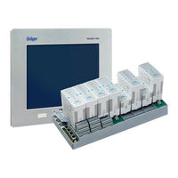
Dräger REGARD 7000 Instructions For Use Manual (164 pages)
Brand:
Dräger
| Category:
Control Unit
| Size: 4.62 MB
Table of Contents
Table of Contents
3
Safety-Related Information
9
Conventions in this Document
9
Meaning of the Warning Notes
9
Typographical Conventions
9
Brands
9
System Description
10
Safety Design
10
System Overview
11
REGARD 7000 Components
12
Intended Use
12
Limitations on Use
12
Approvals Granted
13
Marking
13
Approved Components for Functional Safety and Measuring Function for Flammable Gases, Oxygen and Toxic Gases
14
Approved Components According to NFPA 72
15
Approved Components for Plants in the Maritime Sector
15
Accessories Relevant for Approval
16
Copyright and Licensing Agreements
16
System Components Docking Station
17
Docking Station 4-/8-Slot
18
Technical Data Docking Station 4/8 Slots
19
Modules
19
Ma Input Module / HART
20
Modbus RTU Master Module
23
Digital Input Module
25
Relay Module 240 V AC / 240 V AC Complex
30
Relay Module 24 V DC / 24 V DC Complex
31
Gateway Module
32
Long Distance Gateway
37
Bridge Module
39
Slot Cover
40
Terminal Block 24 Pole DC
41
Terminal Block 24 Pole AC
42
Terminal Block 16 Pole
43
Terminal Block 16 Pole Res
44
Terminal Block 2 Pole / 3 Pole
45
Dashboard
46
Add-On Functionalities
46
Advanced Dashboard 6RU
47
Advanced Dashboard PM
47
Standard Dashboard 3RU
47
Installation & Commissioning
49
System Design
49
System Structure
49
System Limits
50
Prerequisites for the System Structure
51
Additional Requirements for Plants with Measuring Function for Flammable Gases, Oxygen or Toxic Gases
52
System Structure Variants
52
Assembly and Installation
53
Commissioning
54
Requirements for Commissioning
54
Preparation for Operation
54
Switching on REGARD 7000
55
Configuring the REGARD 7000
55
Control
56
Log User in or out
56
Screen Structure (List View)
57
User Roles
57
List and Column View
58
Navigation Bar
58
Navigation Buttons
59
Title Bar of the Channel Display (List View)
60
Buttons on the Menu Bar
60
Buttons of the Display Selection Bar
61
Displays of Progress Bar
61
Generally Used Icons
62
Channel View of the Module Types
63
Icons in the Measured Value and Status Field of the Channel Display with 4 to 20 Ma Input Channels
63
Icons in the Measured Value and Status Field of the Channel Display with Relay Output Channels
64
Icons in the Measured Value and Status Field of the Channel Display with Modbus Output Channels
65
Icons in the Measured Value and Status Field of the Channel Display with Bridge Channels
65
Display Prioritisation
65
Status Signalling with the Presentation of Channel States
66
Side Bar
67
Alarm Confirmation Modes
67
Operation
70
Prerequisites for Operation
70
Prerequisites for Plants in the Area of Functional Safety and Measurement Function for Flammable Gases, Oxygen and Toxic Gases
70
Prerequisites for Plants Conforming to NFPA
71
Requirements for Plants in the Maritime Sector
72
Special Features of Operation of the REGARD 7000 in Combination with a REGARD
72
System Behaviour
74
User Role Concept
76
View Only Role
76
Operation Role
76
Maintenance Role
76
Configuration Role
76
Administration Role
77
View Role
77
During Operation
77
Operation Role
77
During Operation
78
Maintenance Role
78
Docking Station Maintenance
79
Maintenance of Modules
81
Maintenance of Channels and Ports
82
Dashboard Settings
83
Configuration Role
84
General Configuration Procedure
84
Export Configuration and Reports
86
Save or Import Configurations
86
Compare System Configuration (Optional)
87
Copying Port Configuration
88
Port Configuration 4-20 Ma Input Module / HART
89
Module and Port Configuration Modbus RTU Master Module
96
Port Configuration Digital Input Module
101
Relay Module Port Configuration
105
Port Configuration Gateway Module
111
Port Configuration Bridge Module
114
Allocating Card Numbers of a REGARD System to the Bridge Module
117
Dashboard Settings
117
Administration Role
118
Manage Users
118
Set Automatic Login
119
Update Dashboard Firmware
119
Display and Install Add-On Licences
120
Manage System Documentation Library (Optional)
121
Switching off the Dashboard
121
Fault Elimination and Messages
122
General
122
Hart
132
Maintenance
134
Replacing Module (same Slot and same Configuration)
134
Add Module
134
Replace Module (New Slot)
135
Replace Transmitter
135
Additional System Changes
135
REGARD 7000 Configuration Software
136
Introduction
136
Contents of These Help Pages
136
Setting up an Account
136
Operating Concept for the Software
136
Program Interface
136
Editing Configuration Settings
137
Software Operating Modes
138
Offline Configuration Mode
138
Online Configuration Mode
138
Creating a New System Configuration
138
Usable Key Combinations
138
Create New System
138
Add or Remove Docking Station
138
Add or Remove Module
139
Receive and Send Configuration Data
140
Receive Configuration Data
140
Send Configuration Data
140
Compare System Configuration (Optional)
140
Compare Online Configuration
140
Compare Offline Configuration
141
Save and Open Configuration Files
141
Save Configuration Files
141
Save a Copy of a Configuration File
141
Open Configuration Files
141
Set and Change Configurations
141
Set Parameters
141
Copying Port Configuration
142
Select Transmitter
142
Select Measured Gas
142
Set Measuring Range
142
Create Component and Parameter Reports
143
Create and Save Component Report
143
Create and Save Parameter Report
143
Display Dashboard View
143
Select the PC Interface
143
Change Language of the Configuration Software
144
Disposal
145
Technical Data
146
Glossary
148
Annex
150
Compatible REGARD Components
150
Abbreviations
150
Modbus Command Structure
151
Example: Read Register
151
Example: Write Register
151
Meaning of Fields
152
Assignment of the Input Register
152
Channel Types
154
Structure of the State Register of REGARD 7000 Channels
154
Structure of Alarm State Information
155
Structure of Output State Information
155
Assignment of the Holding Register
156
Diagnostics Information for Modbus RTU Master
157
Structure of Notification and Confirmation Register (Acknowledge/Notify Register)
158
Meaning of Data Types
159
PROFIBUS DP and PROFINET Command Setup
160
Downloading the GSD(ML) File
160
Configuration Via the GSD(ML) File Modules
160
Declaration of Conformity
163
Advertisement
Advertisement
Related Products
Dräger REGARD 3900 Series
Dräger RailGard-S1
Dräger RailGard-S4
Dräger RailGard-S6
Dräger RailGard-W1
Dräger RailGard-W4
Dräger RailGard-W6
Dräger REGARD
Dräger REGARD-1
Dräger RespiCare S
Dräger Categories
Medical Equipment
Respiratory Product
Measuring Instruments
Test Equipment
Gas Detectors
More Dräger Manuals
Login
Sign In
OR
Sign in with Facebook
Sign in with Google
Upload manual
Upload from disk
Upload from URL