Table of Contents
Advertisement
Advertisement
Table of Contents

Related Manuals for Dräger RailGard-S1


Summary of Contents for Dräger RailGard-S1
- Page 1 Dräger RailGard Control unit en Installation and Operating manual...
-
Page 2: Table Of Contents
Contents: For your safety......................3 Product description....................4 Product features ......................5 Electrical connections ....................6 Indicating and control elements ................11 Adjustment of the semi-brdge converter for SE Ex sensing heads ....13 Operation........................15 7.1. Signal outputs......................15 7.2. Operating menu ......................16 7.3. Selecting the menu....................17 7.4. -
Page 3: For Your Safety
FOR YOUR SAFETY Follow the instructions Follow the instructions for installation, operation and maintenance. Use in areas subject to explosion hazards The Dräger RailGard is not designed for use in a flammable atmosphere without suitable protection. Liability for proper function or damage Liability for proper function of this apparatus is irrevocably transferred to the owner or operator to the extent that the apparatus has been commissioned, serviced or repaired by personnel not employed or authorised by Draeger Service, or when this apparatus was... -
Page 4: Product Description
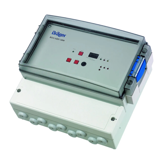
Product Description Dräger RailGard is a freely programmable controller unit for the connection of up to six sensors. Gases of different types can be monitored. The unit can be operated with 1, 2, 3 or 4 alarm thresholds. Depending on the version, Dräger RailGard provides up to six relays. -
Page 5: Product Features
Product Features • Suitable for DIN rail mounting or wall mounting • Supply voltage 24V DC / 230V AC • Up to six 4-20 mA transmitter or Pellistor sensing heads • 1 fault signal via relay • 1 horn contact via relay •... -
Page 6: Electrical Connections
The installation of the control unit shall be done in accordance with industrial standard fixed cable such as NYM-J 3 x 1.5 mm². The supply voltage for the control unit must be equipped with a separate fuse (max. 1A). Connection diagram Dräger RailGard-S1 + S – Power... - Page 7 Connection diagram Dräger RailGard-S4 + S – + S – + S – + S – Power Reset Channel A Channel B Channel C Channel D Error Channel A B C D Concentration RailGard-S4 RS232 + – NC All relays shown are in a de-energised position, when the unit is switched-off ! The Fault relay as well as the Alarm 1 and Alarm 2 relays are normally energised.
- Page 8 Example for connection of a Polytron EC transmitter to Dräger RailGard via a safety barrier...
- Page 9 Installtion of a semi-bridge converters (on Dräger RailGard-W1 and -W4 only) The catalytic sensor in the Polytron SE Ex forms one half of a Wheatstone bridge while the converter board has to provide the second half of this bridge. Therefore it is necesarry to use a semi-bridge converter (Part No. SC00016), if one or more Polytron SE Ex sensing heads are connected to a Dräger RailGard-W1 or - Thus the converter powers the sensor and converts the semi-bridge signal into a 4 to 20 mA signal, suitable for internal processing within the Dräger RailGard.
- Page 10 Connection diagram Dräger RailGard-W4 and -W1 All relays shown are in a de-energised position, when the unit is switched-off ! The Fault relay as well as the Alarm 1 and Alarm 2 relays are normally energised. Terminals for sensor connection: Terminal with short- with...
-
Page 11: Indicating And Control Elements
5. Indicating and control elements Power Reset Error Channel A B C D E F Concentration RailGard-S6 Button F1: Select menu Button F2 Accept value Reset button Reset horn and alarm Potentiometer L Adjust values Power LED (green) Supply voltage present Hu LED (red) Horn Error LED (yellow) - Page 12 The Dräger RailGard provides a scrolling display and three operating levels. The following is displayed in the measuring level: measured values alarm threshold exceeding fault The following is displayed and can be adjusted in the parameter level: threshold values alarm groups alarm functions The following is displayed, can be verified and/or executed in the service level: threshold values...
-
Page 13: Adjustment Of The Semi-Brdge Converter For Se Ex Sensing Heads
Adjustment of the semi-bridge converter for SE Ex sensing heads The converter must be fitted into a powered Dräger RailGard-Wx for the adjustment procedure. A Polytron SE Ex sensing head has to be connected with the converter. 1. Adjusting the supply voltage for the semi-bridge •... - Page 14 2. Adjusting the zero point • Apply zero gas (e.g. 99.99 % by Vol. N ) to the sensor, which corresponds to ZERO (4 mA). • The output current can be checked with a voltmeter at the two test points on the left hand side of the converter (“Measuring Point 4-20mA”).
-
Page 15: Operation
7. Operation 7.1. Signal Outputs Main menu Control Unit Powering up the Dräger RailGard will start a lamp display test. Then the display indicates "WAIT". Transmitter Concentration Further actions are depending on the configuration of the Dräger RailGard. Transmitter not activated Transmitter Concentration Main menu... -
Page 16: Operating Menu
7.2. Operating Menu The output signals of the Dräger RailGard are provided by potential-free relay contacts. These contacts can be used for safety related actions / counter measures. Under normal operating conditions the relays are energized (normally open) – the realys are energized on alarm. -
Page 17: Selecting The Menu
7.3. Selecting the Menu Main menu Menu Set alarm thresholds Menu Test output relays Menu Test alarm thresholds Menu Configuration Menu Sensor type and unit of measurement Continuous signal Auto... -
Page 18: Lev: Setting The Alarm Levels
7.4. LEV: Setting the Alarm Levels Set alarm thresholds Channel No. P is displayed A - F Current value the first time L E V Set the value with R E T potentiometer L Press F2 to accept the value Return to channel (LX) L R E T If this channel is... -
Page 19: Tout: Testing The Output Relays
7.5. TOUT: Testing the Output Relays Push the F1 button to nevigate through the main Test output relays menu until “TOUT” is displayed "Test output relay" Code: X = H relay is energised X = L relay is de-energised Using the F2 button will change the current status of the selected relay. -
Page 20: Tsim: Simulating The Input Channels
7.6. TSIM: Simulating the Input Channels Deactivated channels (no sensor Test alarm connected) are automatically skipped in the thresholds Wait until the desired respective menus! sensor is displayed and press and hold F2 to stop Use potentiometer “L” (by turning the scrolling of the display. -
Page 21: Conf: Configuration Menu
7.7. Configuration Menu Push the F1 button to nevigate through the menu and press the F2 C O N F button to select one of the following sub menues: • Input function • Output function • Horn function Detailed description are followed hereinafter. -
Page 22: C In: Changing The Input Function
7.8. C IN: Changing the Input Function The input function of the Dräger RailGard is set during initial installation or re- configuration of the unit. These can be individually adjusted for each channel and alarm threshold. The following chart shows the available functions. Code Evaluation of measuring signal Reaction at the alarm threshold... -
Page 23: Circuit Diagram For Configuration Of Output Relays And Association Of Channels
7.9. Circuit diagram for configuration of the output relays and association of channels Description of the configuration and association: Level 1 Level 2 The output relays can be assoiated via Level 3 Level 4 switches A1 to A4 to the levels (alarm thresholds) 1 to 4 of channels A to F (see page 22). -
Page 24: Cout: Changing The Output-Relay Function
7.10. COUT: Changing the output-relay function The output relay function of the Dräger RailGard is set during initial installation or re- configuration of the unit. One of the following functions can be associated to the alarm relay: H or S or HM or where: H = with Hysteresis, non latching... - Page 25 Alarm level 1. Input function = L, output function = any Concentration Minutes Alarm level 2. Input function = U, output function = H Concentration Minutes Alarm level 3. Input function = U, output function = HM Concentration Minutes 2 min Alarm level 4.
-
Page 26: Menu For Setting The Output-Relay Function
7.11. Menu for setting the output-relay function C O U T C 1 X X C 1 H C 1 H M C 1 S C 1 S M C R E T C 2 X X C 2 H C 2 H M C 2 S C 2 S M... -
Page 27: C Hu: Setting The Horn-Relay Function
7.12. C HU: setting the horn-relay function The common horn relay contact can be activated or deactivated, independently from the alarm relays. Option: the horn relay can be triggered by a “monoflop” (non-latching function limited to 2 minutes – after 2 minutes automatic reset / acknowledgement). The selected function is marked with "L"... -
Page 28: Sens: Displaying The Unit Of Measurement And The Gas To Be Measured
7.13. SENS: displaying the unit of measurement and the gas to be measured The units of measurement unit and the detectable gases can be displayed in this menu. Following measurement units are available S E N S in the display: Lower explosive limit (German) Lower explosive limit A x x x... -
Page 29: Tuv Function
7.14. TUV Function This function inhibits the evaluation of the 30-minute average value as long as it is active. -
Page 30: Technical Data
8. Technical Data Dräger Dräger Dräger RailGard-S6 RailGard-S4 RailGard-S1 Supply voltage 24 VDC +/-10% Nominal power consumption of Dräger approx. 2.5 W RailGard without sensors connected Number of input channels 4-20mA, input load 490 Ω Fault at <3.5mA (under range) Input Fault at >23 mA (over range) - Page 31 Dräger Dräger Dräger RailGard-W6 RailGard-W4 RailGard-W1 Supply voltage 230 V AC Nominal power consumption of Dräger approx. 3 W RailGard without sensors connected Number of input channels 4-20mA, input load 490 Ω Fault at <3.5mA (under range) Input Fault at >23 mA (over range) hysteresis for fault 0.3 mA Alarms1 to 4 Alarms 1 to 2...
-
Page 32: Ordering List
Ordering List Designation Part No. Dräger Dräger RailGard-S1, 1-channel 4-20mA controller for DIN rail mounting, without power supply unit, 2 SC00010 potential-free normally closed contacts Dräger Dräger RailGard-S4, 4-channel 4-20mA controller for DIN rail mounting, without power supply unit, 2... -
Page 33: Approval
Approval English... - Page 34 Approval-English...
-
Page 35: Gas List
Gas List Gaseliste (can be configured with the configuration software on a laptop or PC) (zu konfigurieren mit der Konfigurationssoftware über Laptop/PC) Gasart Gasart Unbekannt Unknown 63 n-Butylamin n-Butylamine Acetal Acetal 64 sec-Butylamin sec-Butylamine Acetaldehyd Acetaldehyde 65 tert-Butylamin tert-Butylamine Aceton Acetone 66 i-Butylchlorid i-Butylchlorid... - Page 36 Gasart Gasart 126 Dimethylamin Dimethyl amine 190 1-Heptanol 1-Heptanol 127 2.2-Dimethylbutan 2.2-Dimethylbutane 191 2-Heptanon 2-Heptanone 128 2.3-Dimethylbutan 2.3-Dimethylbutane 192 1-Hepten 1-Heptene 129 Dimethylcarbonat Dimethyl carbonate 193 Hexamethyldisilazan Hexamethyldisilazane 130 Dimethyldisulfid Dimethyl disulphide 194 Hexamethyldisiloxan Hexamethyldisiloxane 131 N.N-Dimethylethanola N.N-Dimethylethanolamine 195 n-Hexan n-Hexane 132 Dimethylether Dimethylether...
- Page 37 Gasart Gasart 254 n-Pentan n-Pentane 318 Trimethylamin Trimethyl amine 255 3-Pentanol 3-Pentanol 319 1.3.5-Trimethylbenzo 1.3.5-Trimethylbenzene 256 1-Penten 1-Pentene 320 Trimethylboran Trimethyl borane 257 Phosgen Phosgene 321 Trimethylorthoformia Trimethyl orthoformate 258 Phosphoroxidchlorid Phosphorous oxychloride 322 2.2.4-Trimethylpenta 2.2.4-Trimethylpentane 259 Phosphortrichlorid Phosphorous trichloride 323 2.4.4-Trimethyl-1-pe 2.4.4-Trimethyl-1-pentene 260 Phosphorwasserstoff...
- Page 38 Dräger Safety AG & Co. KGaA Revalstraße1 D-23560 Lübeck Germany Tel. + 49 451 8 82 - 0 Fax + 49 451 8 82 - 2080 www.draeger-safety.com 90 23 818 - GA 4675.895 de/en © Dräger Safety AG & Co. KGaA 2nd edition - December 2004 Subject to alteration...
Need help?
Do you have a question about the RailGard-S1 and is the answer not in the manual?
Questions and answers