Table of Contents
Advertisement
Advertisement
Table of Contents

Related Manuals for Sega THE HOUSE OF THE DEAD


Summary of Contents for Sega THE HOUSE OF THE DEAD
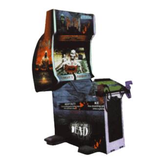
- Page 1 Upright Version Operators’s Manual...
-
Page 2: Table Of Contents
HOUSE OF THE DEAD UPRIGHT TABLE OF CONTENTS INTRODUCTION OF THE OWNERS MANUAL GENERAL PRECAUTIONS 1. NAME OF PARTS 2. ACCESSORIES 3. ASSEMBLING PRECAUTIONS 4. PRECAUTIONS TO BE HEEDED WHEN MOVING THE MACHINE 5. CONTENTS OF GAME 6. EXPLANATION OF TEST AND DATA DISPLAY 6-1 SWITCH UNIT AND COIN METER 6-2 TEST MODE 6-3 MEMORY TEST... - Page 3 13-2 COMPOSITION OF THE GAME BOARD 14. DESIGN RELATED PARTS 15. PARTS LIST ZMB CABINET STD ASSY MONITOR ASSY CONTROL PANEL CONTROL UNIT SENSOR UNIT ASSY SPEAKER AC UNIT SW UNIT/COIN METER ASSY ELEC BASE ASSY MAIN BD 16. WIRING DIAGRAM...
-
Page 4: Introduction Of The Owners Manual
HOUSE OF THE DEAD STD, a new SEGA product. This manual is intended for those who have knowledge of electricity and technical expertise, especially in ICs, CRTs, microprocessors, and circuit boards. -
Page 5: General Precautions
General Precautions Follow Instructions: All operating and use instructions should be followed. Attachments: Do not use attachments not recommended by the product manufacturer as they may cause hazards. Accessories: Do not place this product on an unstable cart, stand, tripod, bracket, or table. The product may fall, causing serious injury to a child or adult, and serious damage to the product. - Page 6 Damage Requiring Service: Unplug this product from the wall outlet and refer servicing to qualified service personnel under the following conditions: a) If the power cord or plug is damaged; b) If liquid has been spilled, or objects have fallen into the product; c) If the product has been exposed to rain or water;...
- Page 7 · On sloped surfaces; · In the vicinity of emergency response facilities such as fire exits and fire extinguishers; · Places subject to any type of violent impact; · Dusty places. Installation Precautions · Verify the amperage of the branch circuit outlet before plugging in the power plug. Do not overload the circuit.
-
Page 8: Name Of Parts
1. NAME OF PARTS Game Specifications Width Length Height Weight PACKAGED GAME 34 x 65 x 80 500 lbs. ASSEMBLED GAME 67 x 47 x 89 400 lbs. 29" NANAO COLOR MONITOR (med MONITOR resolution 24k) GAME POWER REQUIREMENTS 5 Amp 120V 60Hz... -
Page 9: Accessories
2. ACCESSORIES Below is a list of items that are packaged with the HOUSE OF THE DEAD STD game. If you have purchased a game withoout recieving the following accessories please contact your distributer. -
Page 10: Assembling Precautions
3. ASSEMBLING PRECAUTIONS Assembling should be performed as per this manual. Since this is a complex machine, erroneous assembling may cause damage to the machine, or malfunctioning to occur. When assembling, be sure to perform work by plural persons. Depending on the assembly work, there are some cases in which performing the work by a single person can cause personal injury or parts damage. - Page 11 [1.] SECURING IN PLACE (ADJUSTER ADJUSTMENT) Be sure to have all the Adjusters make contact with the surface. Unless the Adjusters come into contact with the surface, the Cabinet can move of itself, causing an accident. This machine has 4 each of casters and adjusters (fig. 3.1a). When the installation position is determined, cause the adjusters to come into contact with the floor directly, make adjustments in a manner so that the casters will be raised approximately 5mm.
- Page 12 [2.] POWER SUPPLY Ensure that the power cord is not exposed on the surface (passage, etc.). If exposed, they can be caught and are susceptible to damage. If damaged, the cord can cause an electric shock or short circuit. Ensure that the wiring position is not in the customer's passage way or the wiring has protective covering.
- Page 13 [3.] ASSEMBLY CHECK In the TEST MODE, ensure that the assembly has been made correctly and IC BD is satisfactory (refer to Section 6). In the test mode, perform the following test: Selecting the MEMORY TEST on the test mode menu screen causes the on-board memory to be tested automatically.
- Page 14 [3.] ASSEMBLY CHECK cont'd In the Test Mode, selecting SOUND TEST causes the screen, on which the sound related BD and wiring connections are tested, to be displayed. Be sure to check if the sound is emitted from each speaker and the sound volume is appropriate. In the TEST MODE menu, selecting C.R.T.
-
Page 15: Precautions To Be Heeded When Moving
4. PRECATIONS TO BE HEEDED WHEN MOVING THE MACHINE When moving the machine, be sure to pull out the plug from the power supply. Moving the machine with the plug as is inserted can damage the power cord and cause a fire or electric shock. -
Page 16: Contents Of Game
5. CONTENTS OF GAME 1.> Inserting a coin(s) causes the credit display on the bottom of the screen to count. Inserting one credit worth of coin(s) changes the message on the bottom of the screen from the "INSERT COIN(S)" to "PRESS START BUTTON" and both of the start buttons will flash. 2.>... - Page 17 4.> If you would like to join in the game at anytime while the other person is playing, insert a coin(s) and press the start button. Also, when credits allowing the game to be played still remain, the start button on the other side will keep flashing. The player can participate i the game by pressing the flashing button.
-
Page 18: Explanation Of Test And Data Display
6. EXPLANATION OF TEST AND DATA DISPLAY By operating the switch unit, periodically perform the tests and data check. When installing the machine intially or collecting cash, or when the machine does not function correctly, perform checking in accordance with the explanations given in this section. -
Page 19: Switch Unit And Coin Meter
6 - 1 SWITCH UNIT AND COIN METER Never touch places other than those specified. Touching places not specified can cause electric shock and short circuit. Adjust to the optimum sound volume by considering the environmental requirements of the installation location. If the COIN METER and the game board are electrically disconnected, game play is not possible. -
Page 20: Test Mode
6 - 2 TEST MODE This mainly checks if the operation of Game BD is accurate, and allows for COIN ASIGNMENTS/GAME ASSIGNMENTS setting Projector adjustments. SELECTION OF TEST ITEMS 1.> Push the TEST BUTTON to cause the following TEST MENU to appear. -
Page 21: Input Test
6 - 5 INPUT TEST When INPUT TEST is selected, the MONITOR will show the following, allowing you to watch the status of each switch. On the screen, periodically check the status of each switch. 1.> By pressing each switch, if the display on the right-hand side of the name of each switch changes to ON from OFF, the SW and the wiring connections are satisfactory. -
Page 22: Sound Test
6 - 7 SOUND TEST This enables sound used in the game to be chacked. Sound related memory and each speaker are checked. Press the SERVICE BUTTON to bring the arrow to the desired sound item to be tested. Pressing the TEST BUTTON causes the desired sound test to appear. Each time the SERVICE BUTTON is pressed, numeral displayued on the screen counts up and sound is emmitted. -
Page 23: Game Assignments
6 - 9 GAME ASSIGNMENTS Selecting the GAME ASSIGNMENTS in the MENU mode cuases the present game settings to be displayed and also the game settings changes (game difficulty, etc.) can be made. Each ite displays the following content. SETTING CHANGE PROCEDURE Setting changes cannot be stored unless the TEST BUTTON is pressed while the arrow is opn EXIT. -
Page 24: Coin Asignments
6 - 10 COIN ASSIGNMENTS Selecting the COIN ASSIGNMENTS in the MENU mode permits you to set the start number of credits, as well as the basic numbers of coins and credits., This mode expresses "how many coins correspond to how many credits." SETTING CHANGE PROCEDURE Setting changes cannot be stored unless the TEST BUTTON is pressed while the arrow is on EXIT. - Page 25 TABLE 6.10a COIN/CREDIT SETTING (COIN CHUTE COMMON TYPE) SETTING FUNCTIONING OF CHUTE #1 SETTING 1 COIN ~ 1 CREDIT SETTING 1 COIN ~ 2 CREDITS SETTING 1 COIN ~ 3 CREDITS SETTING 1 COIN ~ 4 CREDITS SETTING 1 COIN ~ 5 CREDITS SETTING 1 COIN ~ 2 CREDITS SETTING...
- Page 26 1 COIN ~ 1 CREDIT 2 COINS ~ 2 CREDITS SETTING 3 COINS ~ 3 CREDITS 4 COINS ~ 4 CREDITS SETTING 1 COIN ~ 5 CREDITS SETTING 5 COINS ~ 1 CREDIT SETTING 1 COIN ~ 2 CREDITS 2 COINS ~ 1 CREDIT SETTING 4 COINS ~ 2 CREDITS 5 COINS ~ 3 CREDITS...
- Page 27 TABLE 6.10b COIN/CREDIT SETTING (COIN CHUTE INDIVIDUAL TYPE) FUNCTIONING OF COIN SETTING CHUTE SETTING #1 1 COIN ~ 1 CREDIT SETTING #6 1 COIN ~ 2 CREDITS SETTING #8 1 COIN ~ 3 CREDITS SETTING #9 1 COIN ~ 4 CREDITS SETTING #10 1 COIN ~ 5 CREDITS SETTING #11...
- Page 28 MANUAL SETTING Selecting MANUAL SETTING in the COIN ASSIGNMENTS mode displays the following screen. 1.> Determines the Coin/Credit setting. 2.> This sets how many coins should be inserted to obtain one Service Coin. 3.> This sets how many tokens one coin represents. 1 COIN 1 CREDIT 2 COINS 1 CREDIT 3 COINS 1 CREDIT...
- Page 29 NO BONUS ADDER 2 COINS GIVE 1 EXTRA COIN 3 COINS GIVE 1 EXTRA COIN 4 COINS GIVE 1 EXTRA COIN BONUS ADDER 5 COINS GIVE 1 EXTRA COIN 6 COINS GIVE 1 EXTRA COIN 7 COINS GIVE 1 EXTRA COIN 8 COINS GIVE 1 EXTRA COIN 9 COINS GIVE 1 EXTRA COIN 1 COIN COUNTS AS 1 COIN...
-
Page 30: Gun Setting
6 - 11 GUN SETTING Selecting GUN SETTING causes the following screen at the top to appear. This allows the controller sighting to be adjusted. Periodically check the sighting adjustment status on this screen. The screen shown at the left is the sighting adjustment menu mode. Press the SERVICE BUTTON to bring the arrow to the desired adjustment item to select. - Page 31 Shooting the 2 grid displays "NOW CALCULATING" on the center of the screen to allow sighting to be adjusted. Next, the gun mark checking screen shown left appears. When the controller is pointed to the screen, the gun mark is shown on the screen.
- Page 32 6 - 11 GUN SETTING cont'd While pointing the controller at the screen's right-hand end, pressing the left and right buttons causes the impact mark to move left and right. ADXMIN=xxx Determines the adjustment value of the screen's left-hand end horizontal direction. Point the controller at the screen's left-hand end to bring the impact mark to the screen's left-hand end.
- Page 33 ADYMAX=xxx Determines the adjustment value of the screen's lower end in the vertical direction. Point the controller at the screen's lower end to bring the impact mark to the screen's lower end. While pointing at the lower end, changing the adjustment value by pressing the left and right START BUTTONS causes the impact mark to move up and down.
-
Page 34: Bookkeeping
6 - 12 BOOKKKEEPING Choosing BOOKEEPING in the MENU mode displays the data of operating status up to the present are shown on 2 pages. Press the TEST BUTTON to proceed to PAGE 2/2. ° COIN CHUTE#*: Number of coins put in each Coin Chute. °... -
Page 35: Controller (Gun)
7. CONTROLLER (GUN) In order to prevent electric shock and short circuit, be sure to turn power off before performing work by touching the interior parts of the product. Be careful so as not to damage wirings. Damaged wiring can cause an electric shock or short circuit accident. -
Page 36: Replacing The Sensor Board
7 - 2 REPLACING THE SENSOR BOARD The sensor board fits between LENS HOLDER L and LENS HOLDER R. Replace the sensor board by disassembling sensor unit in the following procedure: 1. Disassemble the controller. 2. Remove the sensor unit from COVER R. 3. -
Page 37: Coin Selector
8. COIN SELECTOR HANDLING THE COIN JAM If the coin is rejected when the REJECT BUTTON is pressed, open the coin chute door and open the selector gate. After removing the jammed coin, put a normal coin in and check to see that the selector functions correctly. - Page 38 3. is the coin rejected when inserted while keeping the REJECT BUTTON pressed down? OPTIONAL DOLLAR BILL ACCEPTOR HOUSE OF THE THE COIN DOOR ASSEMBLY USED ON THE DEAD STD COMES EQUIPPED TO ACCEPT A DOLLAR BILL ACCEPTOR. ALL NEEDED WIRING CONNECTIONS ARE CONVIENENTLY LOCATED INSIDE THE GAME FOR THIS APPLICATION.
-
Page 39: Monitor
Using the monitor by converting it without obtaining a prior permission is not allowed. SEGA shall not be liable for any malfunctioning and accident caused by said conversion. -
Page 40: Cleaning The Screen
to send it in an "as is assembled" condition. If these are disabled, what's charged to said high tension voltage can be discharged, causing a very hazardous situation. Therefore, under no circumstances should it be disassembled. STATIC ELECTRICITY; Touching the CRT surface sometimes causes you to slightly feel electricity. -
Page 41: Adjustment Method
> For smear removing solvent, alcohol (ethanol) is recommended. When using chemical detergent, be sure to follow instructions below: a. Dilute chemical detergent with water and dip a soft cloth in and then thoroughly wring it out to wipe smears off. b. - Page 42 NANAO MONITOR: 2001-5242-24-04 (24K)
-
Page 43: Replacement Of Fluorescent Lamp And Lamps
10. REPLACEMENT OF FLUORESCENT LAMP AND LAMPS When performing the work, be sure to turn power off. Working with power on can cause an electric shock or short circuit accident. The Fluorescent Lamp, when it gets hot, can cause burns. Be very careful when replacing the Fluorescent Lamp. -
Page 44: Periodic Inspection Table
11. PERIODIC INSPECTION TABLE The items listed below require periodic check and maintenance to retain the performance of this machine and ensure safe operation. When handling the controller, the player will be in direct contact with it, In order to always allow the player to enjoy the game, be sure to clean it regularly. -
Page 45: Troubleshooting
12.TROUBLESHOOTING Should trouble occur, first check connector connections. PROBLEMS CAUSE COUNTERMEASURES Power is not supplied. Plug in correctly. Power Supply/Voltage is Make sure that power With Main SW ON, not correct. supply/voltage is correct. no activation AC Main fuse Check fuse. Remove the causes the power to cause of overload and be cut off due to... -
Page 46: Game Board
13. GAME BOARD In order to prevent an electrical shock, be sure to turn power off before performing work by touching the interior of the product. Be careful so as not to damage wirings. Damaged wiring can cause an electric shock or short circuit accident. Do not expose the Game BD, etc. - Page 47 13 -2 COMPOSITION OF GAME BOARD GAME BD THE HOUSE OF THE DEAD (610-0396-13054)
- Page 48 14. DESIGN RELATED PARTS...
- Page 49 15. PARTS LIST <1> ZMB CABINET STD ITEM PART NO. DESCRIPTION SEE PAGE 43 ASSY MONITOR 999-0635 CENTER COVER 999-0167 LEVELER 999-0168 CASTER CPT-1019 GUN HOLDER CPT-1020 HOLDER BRACKET GBN-1510 LEG COVER BOX-CASH CASH BOX...
- Page 50 ASSY CONTROL ZMB1-200 PANEL CONTROLLER UNIT ZMB5-2350 CONTROLLER UNIT ZMB5-2300 130-5152 SPEAKER SEE PAGE 51 ASSY MAIN BD *SEE BELOW COIN DOOR ASSY HEX BLT W/S CRM 030-000630-SC M6x30 * FOR INFORMATION CONCERNING THIS PART ASSY PLEASE CALL OUR PARTS DEPARTMENT @ 650-802-1750...
- Page 51 <2> ASSY MONITOR ITEM NO. PART NO. DESCRIPTION GBN-1077 SASH UPPER GBN-1078 SASH LOWER ZMB1-1505 BILLBOARD PLATE 2001-5242-24-04 MONITOR NANAO 29 GBN-1081 ADJUST PANEL TTR-1067 MONITOR MASK GBN-1080 MASK HOLDER LOCAL FL 20W TUBE PURCHASE...
- Page 52 <3> ASSY CONTROL PANEL (ZMB1-2000) ITEM NO. PART NO. DESCRIPTION ZMB1-2001 CONTROL PANEL BLANK STICKER CONTROL ZMB0-2001-B PANEL TOP ZMB0-2004-01 INSTR. PLATE ZMB ENG ZMB0-2001-C STICKER AGENT 1 ZMB0-2001-D STICKER AGENT 2 ZMB0-2001-E BUTTON SHEET SW PB W/L 6V (Y)- 5091-5712-01 IMPERIAL 1 1/2"...
- Page 53 <4> CONTROL UNIT 1P (ZMB5-2300)a CONTROL UNIT 2P (ZMB5-2350)b ITEM NO. PART NO. DESCRIPTION COP-2020 SENSOR UNIT COP-2005 STOPPER PIN 125-5124 TORSION SPRING 253-5404-01 COVER LEFT BLUE 253-5405-01 COVER RIGHT BLUE 253-5406-01 TRIGGER BLUE 999-0648 PROTECT TUBE W/WIRE ZMB1-2301 STICKER CONTROLLER 1P ZMB1-2351 STICKER CONTROLLER 2P 999-0649...
- Page 54 <5> SENSOR UNIT (COP-2020) ITEM NO. PART NO. DESCRIPTION COP-2003 LENS HOLDER L COP-2004 LENS HOLDER R 380-5003 LENS LP 838-11145 SENSOR BD 012-P02606 TAP SCR PH 2.6x6 012-P00306 TAP SCR PH 3x6...
- Page 55 <6> ASSY SPEAKER (130-5152) ITEM NO. PART NO. DESCRIPTION SPEAKER BOX MINI DOME 130-5152...
- Page 56 <7> AC UNIT ITEM PART NO. DESCRIPTION AC BRACKET LOCAL 6 1/4A slow blow PURCHASE 5091-5234 ROCKER SW 25A <8> SW UNIT/COIN METER ITEM PART DESCRIPTION AIN1-1022 SW BRKT 5091-5028 SW PB 1M 2201-5179 VOL CONT B-5K OHM 6011-0042 KNOB...
- Page 57 < > ASSY ELEC BASE ITEM NO. PART NO. DESCRIPTION STVV-00045 STV POWER SUPPLY 838-11650-15 EQ. PWR AMP ZMB 837-12079 GUN SENSOR BD PWR XMFR 120V prim. 560-5250-01 12.8Vsec. 8A...
- Page 58 <10> ASSY MAIN BD-SHEILD CASE (ZMB-0100) ITEM PART NO. DESCRIPTION 105-5218 SHIELD CASE 105-5219-91 SHIELD CASE LID 610-0396-13054 GAME BD 839-0778 FLT BD B-CRX RCT 209-0055 FAN MOTO DC 12V...
Need help?
Do you have a question about the THE HOUSE OF THE DEAD and is the answer not in the manual?
Questions and answers