
Subscribe to Our Youtube Channel
Related Manuals for AEI DK-2890


Summary of Contents for AEI DK-2890
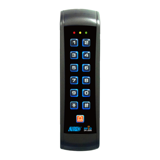
- Page 1 BACK-LIT WEATHERPROOF RFID ACCESS CONTROL KEYPAD DK-2890 User Manual (MK-II) FOR ELECTRIC LOCK AND SECURITY SYSTEMS...
-
Page 3: Table Of Contents
TABLE OF CONTENTS INTRODUCTION ······································································································································· 4 FEATURES ················································································································································ 4 OPTIONAL DEVICES FOR SYSTEM EXPANSION ·················································································· 5 SPECIFICATIONS ···································································································································· 6 INSTALLATION ········································································································································· 7 Precautions ············································································································································ 7 CONNECTION TERMINALS AND INDICATORS ·················································································· 8-9 The On-Board LED Indicators ·················································································································· 9 Pacifier Tone & The LED Signals ··············································································································... - Page 4 Operation Modes ···································································································································· 36 Close The Programming Mode ················································································································ 36 PROGRAMMING SUMMARY CHART ································································································ 37-38 APPLICATION EXAMPLES ···················································································································· 39 Stand Alone Door Lock ························································································································ 39 Basic Wirings of a Stand Alone Lock ····································································································· 39 APPLICATION EXPANSIONS ············································································································ 40-46 The Axiliary Readers & Keypad ···············································································································...
-
Page 5: Introduction
INTRODUCTION DK-2890 is a self-contained two output relay weatherproof keypad. It combines the digital keypad and proximity EM card reader in one unit. The keypad has been designed for stand alone access control applications. It is expandable to work with an optional decoder (DA-2800 or DA-2801) for high security split-decoded operation. It is also... -
Page 6: Optional Devices For System Expansion
OPTIONAL DEVICES FOR SYSTEM EXPANSION The Optional Decoders Available for Split-decoded Operation DA-2800 – Full Feature Decoder with RF Remote Control DA-2801 – Full Feature Decoder The Auxiliary Reader / Keypad Available for Multi-station Operation AR-2802S or A – EM Card Reader AR-2806S or A –... -
Page 7: Specifications
SPECIFICATIONS ● Operating Voltage: ● 12V DC Nominal; 11-15V DC ● Operating Current: .60mA (quiescent) to 100mA ● Operation Temperature: .-20°C to +70°C ● Environmental Humidity: .5-95% relative humidity non-condensing ● Working Environment & Ingress Protection: .Indoor or Outdoor, IP-55 Weatherproof ●... -
Page 8: Installation
INSTALLATION ASSEMBLY DK-2890 PRECAUTIONS 1) Prevent Interference: The EM Card reader is working at the frequency of 125Khz. Installation precautions are necessary. Make sure the location for installation has no strong low frequency electro-magnetic wave. Especially in the range of 100-200Khz... -
Page 9: Connection Terminals And Indicators
CONNECTION TERMINALS AND INDICATORS 1. GREY 7. LIGHT BLUE EG IN N.O. TAMPER N.C. 2. PINK 8. BROWN (–) GND 3. PURPLE 9. WHITE DATA I/O OUTPUT RELAY 2 DOOR BELL N.O. 4. ORANGE 10. YELLOW N.C. OUTPUT 5. RED 11. -
Page 10: The On-Board Led Indicators
8 : GND (-) (Common Ground) A common grounding point of the keypad, it is common to the Black wire, terminal 6. 9 : DATA I/O (Data Input/Output Port for Split-Decoded Operation) A data bus for signal communication with the optional Access Controller in Split-decoded operation and Auxiliary Reader-keypad in multi-station operation. -
Page 11: Preparation For Programming
PREPARATION FOR PROGRAMMING A) CRITERIA FOR CODES AND CARDS 1) Prime Codes The prime codes include the a) User Codes, b) Master Code, c) Duress Codes, d) Super User Codes, e) Common User Codes and f) Visitor Codes. All these codes MUST be unique. It is not allowed to repeat a prime code for second function. -
Page 12: C) List Of User Information
5) EM Card + Proprietary Secondary User Code – Operation Media 3 The keypad accepts programming with each card having its own proprietary user code to work. It prevents any other people can use the lost card to open the door. Card with proprietary user code approach is ideal for the area that high security is the main concern. -
Page 13: Programming And Operation
PROGRAMMING & OPERATION POWER-UP THE KEYPAD The keypad gives power-up delay of 1 minute after power has been applied. It is the time frame designed for setting the keypad to programming mode with DAP code. See the details of “DAP CODE –... -
Page 14: Direct Access To Programming Mode With The "Dap" Code - 2 8 2 8
DIRECT ACCESS TO PROGRAMMING MODE WITH “DAP” CODE -- 2 8 2 8 In case the Master Code is forgotten, apply the following procedures precisely to set keypad into programming mode with DAP code: Switch OFF all the power for 1 minute to ensure that the keypad is fully discharged. Switch ON power again. -
Page 15: The Default Values After Refreshing
THE DEFAULT VALUES AFTER REFRESHING LOCATION PARAMETERS DEFAULT FUNCTIONS & VALUES Master Code 0 0 0 0 Factory Set, Not a default value * Super User Codes Nil ----- User Program Required Common User Code 1 Nil ----- User Program Required Common User Code 2 Nil ----- User Program Required User Codes &... -
Page 16: Master Code
MASTER CODE (Location 01) LOCATION MASTER CODE VALIDATION 4 to 8 Digits (1) LOCATION Key in Location (2) MASTER CODE Master Code is the authorization code for setting the system to programming mode. It is NOT an User Code operating the output relays. The Master Code can be 4 to 8 digits. -
Page 17: Operation And Functions Of The Super User Code
OPERATION AND FUNCTIONS OF THE SUPER USER CODE 1) Operate Output 1 The operation of the Super User Code is just like a normal User Code. Simply key-in the Code with a specific output number for the desired Output. The Super User Code can also be used to reset an operating output timer instantly. - Page 18 4) Inhibit All The User Codes & EM Cards for Output 1 (Disable Access Control Manually) To enhance the security of the access control keypad, the owner can stop the keypad after office hour or while the house is nobody inside. The Output 1 (for door lock control) is inhibited, all the User Codes / Cards for it become invalid and those people holding the User Code or Card are refused.
-
Page 19: Common User Codes For Output 1
COMMON USER CODE FOR OUTPUT 1 (Location 03) The Common User Code 1 is prepared for operating Output 1 as an enhance code. The Common User Code MUST work in the form of “Card + Common Code” to operate the output to increase the security of the access control system. -
Page 20: User Codes/Card For Output 1
USER CODES / CARDS FOR OUTPUT 1 (Location 10) Total 1,100 User Codes / Cards are available for controlling of the two outputs. LOCATION MEDIA USER ID CARD / USER CODE VALIDATION (1) LOCATION – Group 1 – 1,000 User Codes / Cards for controlling Output 1 (2) MEDIA (Operation Media)- please also see page for more information of their security level ... -
Page 21: Examples - Programming And Operation
EXAMPLES – PROGRAMMING AND OPERATION 1) Example 1 -- EM Card Only : i) Programming : Read Card (a) The card is programmed for operating Output 1 (b) The operation is medium EM Card only (c) Take ID number 001 in Group 1 to store the card, which is one of the IDs in 000-999 (d) Put the card close to the reader, one beep confirms the reading (e) Press # to store the “Card”, two-beep confirms a valid entry ii) Operation : (while the system is back to operation mode) - Page 22 3) Example 3 -- EM Card + Secondary User Code i) Programming : Read Card (a) The card is programmed for operating Output 1 (b) The operation medium is EM Card + Secondary User Code (c) Take the ID number 003 in Group 1 to store the Card & Code, which is one of the IDs in 000-999 (d) Put the card close to the reader.
- Page 23 5) Example 5 -- Delete An User Code & / or EM Card (for O/P 1) : i) Delete An User Code or A Lost EM Card User ID (a) Key in the User Group that the User ID belongs to, “10” for Group 1. (b) Key in “5”...
-
Page 24: Visitor Codes
VISITOR CODES (FOR OUTPUT 1 ONLY) (Location 40) The Visitor Codes are temporary user codes for Output 1 (mainly for door strike in access control). They can be programmed as “One Time Codes” or “Codes with Time Limit”. The Visitor Codes will be cleared automatically after use if they are one time codes, or, when the allowed time expires. - Page 25 EXAMPLES: Example 1: Set a “One Time Visitor Code” with the number of “1 2 6 8” for the Output 1 (a) Visitor Code Programming, (b) The Visitor ID, (c) An One Time Code, (d) The Visitor Code, (e) Entry Confirmation Example 2: Set a “Visitor Code”...
-
Page 26: Output Mode & Timing For Output 1
OUTPUT MODE & TIMING FOR OUTPUT 1 (Locations 51 & 52) The two relay outputs are programmable for Start/Stop or Timing modes. Apart from door access control, alarm arm-disarm control, they are also universal timers for automatic operators in industry with their 99,999 seconds (over 24 hours) programmable timer. LOCATIONS OUTPUT MODE &... -
Page 27: System Real-Time-Clock
SYSTEM REAL-TIME-CLOCK (Location 55) This 24 hour real-time-clock provides the daily time base for starting and stopping the function of inhibition to relay output 1 (mainly for electric door lock strike). No real-time-clock setting is required if daily start-stop inhibition at Location 56 is not enabled. -
Page 28: Start & Stop Times For Daily Inhibition Of Output 1
START & STOP TIMES FOR DAILY INHIBITION OF OUTPUT 1 (Location 56) Setting with start and stop times into the keypad, the real-time inhibition period for output 1 will recycle daily until the time settings are cleared. This function works with the real-time-clock. Set up the real-time at Location 55 is necessary. For safety reason, the Egress Button is designed always valid. - Page 29 Programming and Operation Examples: (i) Set the starting and stopping time for the real-time inhibition period a) Set Inhibition Period from 12:30 PM (today) – 1:30 PM (same day) for lunch time: b) Set Inhibition Period from 6:30 PM (today) – 8:15 AM (next day) for office close: ...
-
Page 30: Personal Safety And System Lock-Up
PERSONAL SAFETY AND SYSTEM LOCK-UP (Location 60) LOCATION LOCK-UP OPTIONS VALIDATION 1 to 2 Digits (1) LOCATION Key in Location (2) LOCK-UP OPTIONS The Options are represented by the following Numbers. They are described below: --- After 10 successive false Card/User Code trials, the keypad locks during 60 seconds. - (Default) ... -
Page 31: User Code Entry Mode - Auto Or Manual
USER CODE ENTRY MODE – Auto or Manual (Location 70) LOCATION ENTRY MODES VALIDATION (1) LOCATION Key in Location (2) USER CODE ENTRY MODES Two modes 1 and 2 are available for User Code entry options. The EM Card is always in Auto Entry Mode and is not affected by the selection here. -
Page 32: Output Operation Announcer
OUTPUT OPERATION ANNOUNCER (Location 72) LOCATION FUNCTION MODES VALIDATION (1) LOCATION Key in Location (2) FUNCTION MODES FOR OUTPUT ANNOUNCER Output announcer gives notification beep on the operation status of the outputs. There are two notification modes available for the selection.The notification is also OFF while the Pacifier Tone OFF mode in the Location 71 is selected. -
Page 33: Intelligent Egress Button - An Unique Feature Of A Contemporary Keypad
INTELLIGENT EGRESS BUTTON – AN UNIQUE FEATURE OF THE KEYPAD INTRODUCTION Most of the keypads for access control are just for controlling “Going In” from outside. It is not enough for today’s access control systems. In fact, controlling “Going Out” is also very important in some public passage areas those are not allowed to use locks or digital keypads for stopping of “Going Out”... - Page 34 High Traffic Passage: A short buffer time may be necessary for opening a door outward after pressing the egress button for those exits open to a high traffic passage. An egress button with short delay and warning beeps helps the user to pay attention to the people passing by to prevent hitting them when the door is pushed outward.
-
Page 35: Egress Delay , Warning And Alarm
EGRESS DELAY , WARNING AND ALARM (Location 90) LOCATION CONFIGURATIONS DELAY TIME VALIDATION (1) LOCATION Key in Location (2) CONFIGURATIONS OF THE EGRESS WARNING AND ALARM Key in the number to enable 1 of the configurations described below: ... - Page 36 NOTE: 1) Momentary Contact -- The Egress Delay starts to count when the egress button is momentarily pressed. Output 1 activates automatically (door is released) when the delay time reaches. Holding Contact -- The user MUST hold the egress button in contact for the whole period of the Egress Delay time until Output 1 activates.
-
Page 37: Operation Modes
OPERATION MODES (Location 94) The keypad is programmable for keypad mode to work stand-alone for door control directly or for server mode to work with a split-decoder for high security access control. LOCATION OPERATION MODES VALIDATION (1) LOCATION ... -
Page 38: Programming Summary Chart
PROGRAMMING SUMMARY CHART ENTRY LIMITS & CODE FACTORY CODE ENTRY FUNCTION LOCATION DEFAULT OPTIONS Master Code 4-8 Digits MASTER CODE Super User Code 4-8 Digits SUPER USER CODE Common User Code for COMMON USER CODE 1 O/P 1 4-8 Digits Common User Code for... - Page 39 FACTORY ENTRY LIMITS & CODE FUNCTION CODE ENTRY LOCATION DEFAULT OPTIONS CODE 1 - FUNCTION MODE: 1---Momentary, No warning 2---Momentary, with Mode = 1 warning Momentary, Egress Delay Warning & 4---Hold Contact, No No warning CODE 1 CODE 2 Alarm warning TIME = 0...
-
Page 40: Application Examples
APPLICATION EXAMPLES STAND ALONE DOOR LOCK ELECTRIC LOCK DK-2890 NOTE: Connect the 1N4004 as close as possible to the lock in parallel with the lock power terminals of the lock to absorb the back EMF to prevent it from damaging the keypad. The 1N4004 is not required if the electric lock is AC operated. -
Page 41: Application Expansions
The wiring is very simple. Just connect all the related devices in parallel with the Data I/O Bus. The DK-2890 is the server that manages the data among them. A Multi-station System provides higher security in access control and user convenience to operate an electric lock at different locations. -
Page 42: The Split-Decoders
The Split-decoders (Optional) DA-2800 DA-2801 Decoder with RF Remote Control Standard Decoder Connection Terminal OUTPUT 1 OUTPUT 2 OUTPUT 3 ... -
Page 43: Dual-Station Access Control Door Lock
Owner can select an auxiliary reader AR-2802 or an auxiliary reader-keypad AR-2806, AR-2807 or AR-2809 and connect it with the master keypad DK-2890 to expand the system with dual-station for user convenience. Simply connect the reader or the reader-keypad in parallel with the Data I/O Bus of the master keypad. -
Page 44: Multi-Station Access Control Door Lock
2) Multi-station Access Control Door Lock Description This is an expansion of application (1). The DK-2890 is expandable to a multi-station system for user convenience with the auxiliary readers AR-2802 and/or the auxiliary reader-keypads AR-2806, AR-2807 &r AR-2809. Total 3 auxiliary readers or reader-keypads can be connected in parallel with the Data I/O Bus and they provide the same functions like the master keypad in using cards and user codes. -
Page 45: Split-Decoded Access Control Door Lock
DA-2800 or DA-2801. The decoder is inside the house with all the input and output installations connecting to it. The DK-2890 manages the data in the system with its Data I/O Bus. The decoder operates the door lock and the appliances directly according to the commands from the keypad unit. -
Page 46: Split-Decoded Multi-Station Access Control Door Lock
Data I/O Bus. They provide the same functions like the master keypad in using cards and user codes. The DK-2890 that is the server of the system manages the data with its Data I/O Bus among the associated devices. This approach gives high security in sabotage prevention and user convenience. -
Page 47: Auxiliary Information
AUXILIARY INFORMATION DRY CONTACT A dry contact means that no electricity is connected to it. It is prepared for free connections. The Relay Output contacts provided in this keypad system are dry contacts. N.C. Normally Closed, the contact is closed circuit at normal status. It is open circuit when active. N.O. - Page 48 AEI PROTECT-ON SYSTEMS LIMITED www.apo-hk.com ...
Need help?
Do you have a question about the DK-2890 and is the answer not in the manual?
Questions and answers