Table of Contents
Advertisement
(F) OUTPUT 3 (WHITE/RED WIRE)
+12V
WIRE HARNESS
(9)
(10)
(11)
EXTERNAL
(12) WHITE/RED
RELAY
(13)
(14)
APPENDIX
DRY CONTACT
A dry contact means that no electricity was connected to it. It is prepared for free connections. The Relay
Output contacts provided in this keypad system are dry contacts.
N.C.
Normally Closed, the contact is closed circuit at normal status. It is open circuit when active.
N.O.
Normally Open, the contact is open circuit at normal status. It is closed circuit when active.
TRANSISTOR OPEN COLLECTOR OUTPUT
An open collector output is equivalent to a Normally Open (N.O.) contact referring to ground similar to a relay
contact referring to ground. The transistor is normally OFF, and its output switches to ground (-) when active.
The open collector can only provide switching function for small power but it is usually good enough for
controlling of an alarm system. The Duress, Inter-lock, Key Active Outputs of the keypad are open collector
output.
OPEN COLLECTOR
OUTPUT ----
Output switches to
( )
ground when activates
An Innovative Product
Developed By:
MANUFACTURED BY:
AEI PROTECT - ON
SYSTEMS LIMITED
Output 3 is an open collector output prepared for
N.C.
auxiliary controls. It may be used for arm-disarm
of a security system, enable and disable of a
COM
keypad or a protection zone etc.; it can also
drive a relay to give full function of N.C. and N.O.
outputs as like the output 2 making the keypad a
N.O.
ture 3 output system.
N.O. CONTACT
OUTPUT ----
EQUIVALENT
Output switches to
( )
ground when activates
SINCE 1979
R
ADVANCED ELECTRONICS
INDUSTRY
20
MULTI-PURPOSE SELF-CONTAINED
DIGITAL ACCESS CONTROL KEYPAD
Programming & Installation Manual
AND SECURITY SYSTEM INSTALLATIONS
40IN9523
M-100705
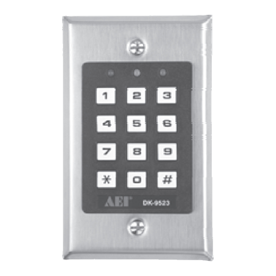
DK-9523
FOR ELECTRIC LOCK, INTER-LOCK
Advertisement
Table of Contents

Related Manuals for AEI DK-9523


Summary of Contents for AEI DK-9523
- Page 1 Output switches to ground when activates ground when activates DK-9523 Programming & Installation Manual FOR ELECTRIC LOCK, INTER-LOCK An Innovative Product AND SECURITY SYSTEM INSTALLATIONS Developed By: MANUFACTURED BY: SINCE 1979 AEI PROTECT - ON ADVANCED ELECTRONICS 40IN9523 SYSTEMS LIMITED INDUSTRY M-100705...
- Page 2 Apart from that it is also the perfect choice for controlling security systems, automatic operators and ALARM CONTROL PANEL (10) machinery. (11) (10) (12) DK-9523 consists two application softwares of Single User Mode for the general Users, and Multi-User Mode for (11) (13) 1.5K (12) LOW POWER (14) the advanced Users.
- Page 3 APPLICATION HINTS FOR THE AUXILIARY FACILITIES EG IN EGRESS INPUT A Normally Open (N.O.) input terminal refers to ( ) ground, with the help of a normally open button to activate the Output 1 for the same time period as the user code. Egress button is usually put inside the house near the door. (A) TAMPER N.C.
- Page 4 The Green LED at the centre is a status indicator at normal condition. The lamp changes to steady Red while the auxiliary Red LED is energized. This inter-lock application example utilizes one DK-9523 and a power supply with inter-lock controller, AD-2312. The DK-9523 power supply provides the power source for the whole system including both electric locks and the keypad.
-
Page 5: Programming Options
(OPEN DOOR 2 FROM INSIDE) 4 digits, fixed Personal Master Code & Super User Code An inter-lock system needs two door controllers. This application example uses two DK-9523 with simple cross wire 4 digits, fixed User Code 1 for output 1 with Duress Code function connection on their "Output 1 Inhibit"... - Page 6 D) Configuration of Output Modes 2) BASIC WIRINGS FOR ALARM ARM-DISARM AND STAND ALONE DOOR LOCK Installer Programming Locations Code of Duration Validation Comments TERMINALS 1 to 999 Output 1 in Momentary Mode from 1 to 999 seconds Output 1 in Start / Stop Mode (toggle) ( + ) ( ) - Output 1 in Start / Stop Mode (toggle) with accelerated code OUTPUT 1...
- Page 7 APPLICATION EXAMPLES I) Pacifier Tones (Keypress Acknowledgement Tones) Installer Programming Locations Code of Functions Validation Comments 1) BASIC WIRINGS OF A STAND ALONE DOOR LOCK WITH INHIBIT Pacifier tones available on keypress AUTHORIZATION CODE AND INDICATION All pacifier tones are off. Good for place requires silent environment J) Main LED Flashing ON-OFF -- Installer Programming Locations Code of Functions...
- Page 8 Code Entry Limitation in Multi-User Mode due to Duress Code SPECIFICATIONS The system comes with DURESS function for the user code 1 in Single User Mode and all the user codes of Group Operation Voltage: 1 in Multi-User Mode; The DURESS CODE is set up by the system automatically with the first digit of the User 12V 24V AC/DC, No Jumper is Required for voltage selection Code "+2".
- Page 9 For example: The User Codes in Group 1 The Corresponding Duress Codes After the keypad is in programming mode, you may go to any Location for your programming options one by one, please see Programming Options Summary Chart for the feature details. 8321 0321 11223...
- Page 10 The Personal Master Code is a Super User Code to command the outputs. This feature allows the owner 2) Programming -- Set the above requirement into the keypad to use only one code to operate several keypads if they are having the same Master Code but different 0000 * -------------------- System has been set in programming mode with the factory-set Master Code user codes.
Need help?
Do you have a question about the DK-9523 and is the answer not in the manual?
Questions and answers
Hat der Tür Öffner eine Batterie