
Related Manuals for Apache Labs ANDROMEDA ANAN-7000DLE MKII


Summary of Contents for Apache Labs ANDROMEDA ANAN-7000DLE MKII
- Page 1 openHPSDR ANDROMEDA/ ANAN‐7000DLE MKII with Integrated PC User Guide ANDROMEDA Manual Page 1 of 56 ...
- Page 2 This document contains the words Apache, ANDROMEDA, ANAN in reference to the Apache Labs Transceiver products. http://www.apache‐labs.com In cooperation with VK6PH, NRØV, W5WC, K5SO, LA2NI, G8NJJ and the OpenHPSDR Hardware and Software Projects http://openhpsdr.org All images and manufacturer data is copied here with permission of the owner Apache Labs Note: Customer is responsible for FEDEX shipping and all local Customs, Tariff, VAT, Taxes and incidental charges within their delivery [address] Country. Please contact Apache Support support@apache‐labs.com for details regarding your order or shipping charges. Apache Labs LLC, Inc. ‐ Declarations of Conformity The ANDROMEDA complies with FCC Part 97 rules for the Amateur Radio Service. It has been confirmed by the relevant authorities that the ANDROMEDA DOES NOT require FCC certification. Under rule 97 Amateur radio equipment with the exception of amplifiers and scanning receivers are exempt from certification, however, must conform to rule 97 which states that harmonic and spurious emissions must be below 43dB of the transmitted out up to 30MHz and 60dB beyond that. Apache Labs Products CE and RTTE Certified CE & EC Radio and telecommunications terminal equipment [RTTE] Certification. We are pleased to announce that the ANAN series HF & 6M SDR transceivers including ANDROMEDA is now CE and RTTE certified as per EU trade directives, ANDROMEDA is RoHS compliant as well, we ensure that our products are of the highest quality and meet international standards of quality and compliance. ANDROMEDA Manual Page 2 of 56 ...
-
Page 3: Table Of Contents
Contents Contents 1 Key Features ............................ 7 1.1 Benefits ........................... 7 1.2 Architecture .......................... 8 1.3 Writing Style .......................... 9 1.4 ANDROMEDA Design Team ..................... 9 2 Front Panel Functions ........................ 1 0 2.1 Touchscreen .......................... 1 0 2.2 Rotary Encoders ........................ 1 1 2.2.1 ... - Page 4 5.6 Panadapter displays ...................... 2 0 5.7 Meter Mode .......................... 2 0 5.8 Changing antennas ........................ 2 0 5.9 Using the Softkey Menus ...................... 2 1 5.9.1 Quick Menu ........................ 2 1 5.9.2 RX Menu ........................ 2 1 5.9.3 VFO Menu ........................ 2 1 5.9.4 TX Menu ........................ 2 2 5.9.5 ...
- Page 5 6.7 Puresignal .......................... 3 1 6.7.1 Setting Up Puresignal .................... 3 1 6.7.2 Operating with Puresignal .................... 3 2 6.7.3 External Linear Amplifier .................... 3 2 6.8 ATU ............................ 3 2 7 Configuring Thetis and ANDROMEDA ................... 3 3 7.1 Thetis Setup Screen ....................... 3 3 7.2 ...
- Page 6 11.2 References .......................... 5 6 ANDROMEDA Manual Page 6 of 56 ...
-
Page 7: Key Features
1 Key Features The ANDROMEDA/ ANAN‐7000DLE MKII i5/i7 Amateur Radio Transceiver is a modern direct‐down‐ conversion [DDC] receiver, and direct‐up‐conversion [DUC] transmitter, Software Defined HF transceiver plus 6 Meters. ANDROMEDA has a proud heritage from the TAPR Hermes Transceiver introduced in 2012. It is based upon the established 7000DLE mk2 RF, DSP and PC, plus an integrated front panel with radio controls and touch screen display. The ANAN‐7000DLE MKII i5/i7 model is without the Andromeda front panel, it is capable of being upgraded with the Andromeda Front panel. This model supersedes the previous Integrated PC ANAN‐7000DLE MKII and includes a number of improvements and upgrades to the hardware. ANDROMEDA firmware updates can be easily installed via the radio’s standard Ethernet connection, eliminating the need for special mechanical or programming adapters. It is not necessary to open the ANDROMEDA cabinet to update the firmware. A “Bootloader” switch has been added to the back panel of the ANDROMEDA for ease of future updates. The ANDROMEDA transceiver has been designed for the THETIS PC Software Defined Radio program. THETIS has the latest SDR processing from the OpenHPSDR line and is based on the proven WDSP libraries. It has full support for dual receivers, antenna diversity and PureSignal TX linearization. However, other SDR programs could be used including those written for Windows®, Linux, MacOS/X®, Android, RaspberryPi, and other operating systems. The command interfaced to the front panel uses simple published CAT commands and other programs could be adapted to support it. 1.1 Benefits ANDROMEDA – Second to none! Using Direct Down Conversion with an ultra low phase noise clock yields an RMDR of 116dB @ 2KHz separation, this means that close in weak signals will not be masked by the receiver’s phase noise. The transmitter specifications are also off the chart, use of a new 16‐bit DAC with an ultra low noise clock source results in transmit phase noise better than any other product available in the market. Use of LDMOS drivers and an optimized final Amplifier stage with adaptive Predistortion Algorithm (PureSignal) yields transmit IMD of better than 60dB, this is at least 20dB better than any Class A transmitter and over 30dB better than the competition. ... -
Page 8: Architecture
1.2 Architecture RX2 Variable A‐ D Digital Audio RF Keyer Atten‐ Conver‐ Down‐ Codec Filters uator Convert VFO Ethernet Band Tune 2 Channel Variable A‐ D Digital RF Receiver Atten‐ Conver‐ Down‐ Filters uator Convert VFO Band Tune Ethernet User interface Digital Ant, Down‐ T/R ... -
Page 9: Writing Style
1.3 Writing Style In this manual: A control / setting name is highlighted bold The user setting for that control is underlined. Menu > Equalizer means open the “Equaliser” setting on the program’s menu Menu > Setup > DSP > RX2 means open the setup form using Setup on the menu, then select the DSP tab, RX 2 sub‐tab So for example this instruction would indicate a gain control setting: Set the RX1 AF encoder to 30. 1.4 ANDROMEDA Design Team Phil Harman, VK6PH Doug Wigley, W5WC Dr. Warren C. Pratt, NR0V Kjell Karlsen, LA2NI Abhishek Prakash Dr. Joe Martin, K5SO John Melton, G0ORX/N6LYT Adam Farson AB4OJ/VA7OJ Laurence Barker G8NJJ ANDROMEDA Manual Page 9 of 56 ... -
Page 10: Front Panel Functions
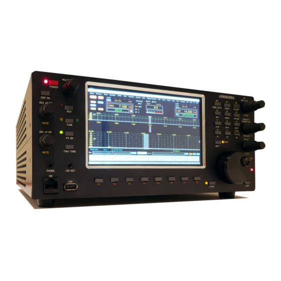
2 Front Panel Functions The front panel provides the first port of call to control your radio. A touchscreen display provides a PC display from the PC control application; rotary encoders and pushbuttons provide access to the most commonly used controls. 2.1 Touchscreen The touchscreen is a full function PC display with capacitive touch sensing. It provides the front panel display for Thetis. Additional displays can be connected via USB‐C hub devices connected to the rear panel connectors. The Thetis “ANDROMEDA” display screen layout is as follows: 1. At the top is a normal PC application title bar and menu bar. 2. At the bottom of the screen is a status bar. Is shows screen size, CPU load, power supply voltage and current, RX and TX antenna, multifunction control setting and the current data and time. 3. Above the status bar is a set of 8 softkey menu buttons. These provide access to many of the radio’s features. These are activated by clicking the screen button, or the pushbutton below it. 4. Above that are controls for the central screen area. 5. The central screen area can be user configured but normally provides waterfall, panadapter or a combined panadapter & waterfall display. RX 1 can be shown alone, or both receivers can be shown. 6. The top area provides various controls and displays: a. At the left, buttons shows the status of several major functions. b. The VFO A display shows the mode, frequency & band segment for VFO A together with RX1 noise reduction, AGC and attenuation settings c. RIT, XIT, VFO tune step, VFO sync and band split are to the right of VFO A ANDROMEDA Manual Page 10 of 56 ... -
Page 11: Rotary Encoders
d. The configurable multimeter display can show several RX and TX indications; the currently selected RX and TX settings are shown. e. To the right of the multimeter, the ATU settings are shown. There is a slider that pops up if a rotary control is turned, to show its current position. Finally the VFO B / RX2 display is at the right of the bar. The top bar indications are as follows: Top row: nose reduction; noise blanker; spectral noise blanker; ANF Bottom row: AGC speed, attenuation Lit blue if CLICK TUNE VFO Display Current mode VFO frequency box Indicates MUTE Current band segment RX2 / VFOB selected RX and TX meter modes RX1 / VFOA selected ATU indicator Blue if VFO A/B SYNC Blue if Split RX/TX Centre Section VFO Step Multimeter Rotary control position (auto‐hides) 2.2 Rotary Encoders 6 dual encoders provide a range of RX and TX controls. 2.2.1 VFO The VFO encoder can be selected to control VFO A or VFO B. In most cases VFO A will operate RX1 while VFO B will operate RX2. The VFO controlled by the encoder is selected using the A/B pushbutton. The indicator by the button is lit if VFO A is selected. The encoder provides 480 steps per revolution. With 10Hz steps selected for VFO tuning, that corresponds to 4.8KHz per revolution which is ideal for SSB and CW operation. ... -
Page 12: Rx1 Af/Rf Gain
2.2.2 RX1 AF/RF Gain Pressing the upper knob toggle RX1 Mute on/off Turning the upper knob adjusts the RX1 AF gain or “volume”. A slider pops up to the right of the multi‐meter to indicate the current position. Turning the lower knob adjusts the RX1 AGC, which behaves similarly to RF gain in an analogue receiver. A green bar is normally shown in the spectrum view, which should be adjusted to sit just above the noise floor. A slider pops up to the right of the multi‐meter to indicate the current position. If the RX1 AF encoder knob is pressed down and turned while held down, the PC & display brightness is changed. The brightness setting will be saved and restored every time the radio is powered up. 2.2.3 RX2 AF/RF Gain Pressing the upper knob toggle RX2 Mute on/off Turning the upper knob adjusts the RX2 AF gain or “volume”. A slider pops up to the right of the multi‐meter to indicate the current position. Turning the lower knob adjusts the RX2 AGC, which behaves similarly to RF gain in an analogue receiver. A green bar is normally shown in the spectrum view, which should be adjusted to sit just above the noise floor. A slider pops up to the right of the multi‐meter to indicate the current position. 2.2.4 Drive/Multifunction Pressing the upper knob toggles the multifunction knob between selecting the value of a setting, and choosing which setting is operated. Press the knob to begin selecting another function. Turn the knob to choose the function required (it is shown in the status bar). Press again to select that ... -
Page 13: Filter High/Low Cut
2.2.5 Filter High/Low Cut Pressing the upper knob resets the centre frequency of the filters. The filter high cut knob adjusts the upper audio frequency passband of the RX filter. This is useful to remove QRM from the passband. If you hear a high audio frequency interfering signal, use this knob to remove it. The filter low cut knob adjusts the lower audio frequency passband of the RX filter. This is useful to remove QRM from the passband. If you hear a low audio frequency interfering signal, use this knob to remove it. 2.2.6 Diversity Gain/Phase Pressing the upper knob toggles between fine and coarse adjustment of the diversity gain and phase. In most cases coarse will be OK. Diversity uses both receivers with separate antennas to maximise a weak signal, or to cancel interference. The Diversity Gain control adjusts the gain of RX2 to optimise the enhancement of a wanted signal or rejection of QRM. Open the Diversity screen to see the effect. The Diversity Phase control adjusts the phase of RX2 to optimise the enhancement of a wanted signal or rejection of QRM. Open the Diversity screen to see the effect. 2.2.7 RIT/Unallocated Pressing the upper knob clears the RIT frequency. The RIT/XIT knob selects a frequency offset for the receiver (RIT) or transmitter (XIT) from that displayed in the VFO window. Commonly used to optimise reception of a signal where the other operator has not exactly matched your frequency. RIT or XIT is selected according to the RIT/XIT pushbutton. This knob is unassigned. It can be assigned to any rotary encoder function in the ANDROMEDA settings editor. ... -
Page 14: Softkey Buttons
TUNE Toggles between RX mode and TUNE mode. In tune a low power carrier is transmitted to facilitate ATU matching. An LED indicator lights for TUNE. PS ON Turns on or off the Puresignal TX linearization algorithm. An LED indicator is lit if Puresignal is enabled. TWO TONE Initiates a “two tone” TX test to allow Puresignal to optimise linearity. 2.3.2 Softkey buttons F1‐F8 operate the 8 “softkey” menu buttons at the bottom of the ANDROMEDA display. These could be reconfigured to other functions if you prefer to use the touchscreen softkey buttons. 2.3.3 Band Buttons The group of buttons above the VFO tuning knob can be used as “band select” buttons when “SHIFT” is selected. Shift is activated by pressing the SHIFT button, and an indicator lights. To select a new band, simply press its button when SHIFT is lit. These buttons also have other functions when SHIFT is not lit: Mode Opens the “mode dependent settings” form for quick access to settings important Settings for the current operating mode. RX2 Turns on/off the second receiver channel. Mode + Selects the next higher operating mode. Press and hold for more than 2 seconds to open the “mode select” form. Mode ‐ Selects the next lower operating mode. Press and hold for more than 2 seconds to open the “mode select” form. Filter + Selects the next higher variable bandwidth filter. Press and hold for more than 2 seconds to open the “filter select” form. Filter ‐ Selects the next lower variable bandwidth filter. Press and hold for more than 2 seconds to open the “filter select” form. A>B Copies the settings from VFO A to VFO B B>A Copies the settings from VFO B to VFO A ... -
Page 15: Editing The Front Panel Control Assignments
2.3.5 Editing the Front Panel control Assignments The functions for each encoder and pushbutton (with the exception of the Power button) can all be changed by the user. Also the menu bar buttons on the PC screen can be changed. See section 7.3 for details of how to do this. 2.3.6 Front Panel Connections CW Key 3.5mm stereo jack socket. Connect a CW (morse) key: this may be a “straight” key or iambic keyer. Do not use a mono jack plug: TX mode will be continuously asserted! Phone Connect stereo headphones. This is a standard 3.5mm stereo jack socket. The internal speakers will be muted when connected. MIC Connect a microphone with 8 pin RJ45 connections. USB A USB socket from the internal PC; useful to connect memory sticks etc. CW Key Tip = Dit Tip = Key Ring = Dah Ring = no connect 3.5mm Stereo Jack: 3.5mm Stereo Jack: Paddle Connections Straight Key Connections Mic Please Note the i5/i7 Version without the Andromeda Front panel uses 6.25mm Audio Barrel Connectors ... -
Page 16: Rear Panel Connections
3 Rear Panel Connections GND RF earthing stud ANT 1 ‐ 3 3 independent TX & RX1 Antenna connectors RF Bypass RX input bypassing RX filtering. Puresignal feedback input for an external PA EXT1 RX input bypassing the T/R switch RF XVTR In Transverter RF input ADC2 RX2 Antenna XVTR Low power TX signal to Transverter 10MHz in 10MHz reference input Ext Fan DO NOT USE Power 13.8V DC PowerPole® 13.8V DC, 30A power supply input 3.5mm Audio PC 3.5mm “TRRS” audio connector USB3, USB‐C and PC USB3.1 Type A and Type C connectors. A keyboard and mouse can be PC Thunderbolt connected. A USB3 hub will provide HDMI for an external display Wi‐Fi Wi‐Fi antenna connection OC Out 7 user configurable Open Collector Outputs Dig In 1 User digital input 1 Dig In 2 User digital input 2 L Line in ... -
Page 17: Installation
4 Installation 4.1 Important Operation tips Do not cover rear or bottom ventilation holes. Proper air circulation throughout the ANDROMEDA Transceiver is necessary to prevent possible overheating and failure. The radio is factory calibrated to 100W into a 50 ohm Dummy Load. Operating at higher levels will damage the radio. Please review CCW and ICAS specifications. Data/AM/FM and other continuous duty modes must be operated at 30W or less to remain within the operational limits of the radio. Input voltage must be 13.8vdc +/‐ 5%, well regulated at 30A Peak and proper POLARITY must be observed. DISCONNECT the Antenna during Thunderstorms or when not in use. Please ensure that you select the correct hardware model during software setup: ANAN‐7000DLE. Install the supplied rubber feet on the bottom of the case for proper cooling. 4.2 Heat Dissipation ANDROMEDA uses a heavy duty Aluminium heat sink to dissipate heat with temperature controlled internal and optional external fan. ICAS [100W] operation SSB, CW and all ICAS modes [Intermittent Commercial/Amateur Service] 100W PEP The Power Amplifier MOSFET transistor has characteristics that far exceed the needs of normal Transceiver operation. 4.3 Quick Start Make sure that you have the following equipment and accessories: A 13.8v 30A Power Supply 50 Ohm Dummy load capable of at least 100W load capacity DC Power Cable (Supplied) Optional Keyboard/Mouse (either USB or Wireless) USB 3.0 HUB With the Radio switched off: 1. Connect the Keyboard/Mouse to one of the USB ports, if required 2. Connect the DC power cable to the Power Pole connector. Please ensure that the RED side corresponds with the Positive supply. ... - Page 18 8. Once you have tested basic functionality you may remove the Dummy load and connect the Antenna ensuring good SWR before you are ready to go on Air! It is possible to connect additional external displays if required using a USB hub connected to the rear USB3 connectors. Do we need to cover APIPA setup for network connection to Orion? ANDROMEDA Manual Page 18 of 56 ...
-
Page 19: Getting Started
5 Getting Started This section gives a simple guide to standard operations using the Thetis program. As with many complex programs there are several ways to achieve most outcomes. This manual concentrates on the “front panel” functionality of Thetis. More information is available in the separate Thetis manual which covers the whole application. 5.1 Powering Up, Running Thetis 1. Switch on the radio by pressing the Power button momentarily. This will activate the power supply and the PC will boot. Its display will appear on the touchscreen. 2. Double click the Thetis icon to run the Thetis program. 3. Click the on‐screen “power” button to start Thetis operation. 4. The radio will spring into life; audio will be heard from the speakers. To power down: 1. Shut down the windows PC 2. Press and hold the Power button for a couple of seconds until the red power LED is unlit. Check what I’ve written for power down! 5.2 VFO Selection & Tuning The VFO knob will operate either VFO A or VFO B, depending on which is selected. As the knob turns the tuned frequency is displayed and the panadapter/waterfall display will be updated. To switch between VFO A and VFO B, use the A/B button. The LED is lit when VFO A is selected. Tuning can also be accomplished by clicking on the touchscreen. 5.3 Band Selection To change band, the group of buttons above the VFO encoder have a “band select” function. 1. Press the SHIFT button. Its indicator will light up 2. Press a button corresponding to the required band. The radio will change band, and select the operating mode and filter setting last used on that band. 3. To cancel a SHIFT: press SHIFT again and its indicator will go out. There is also a band select form that can be invoked from the softkey menus. If the same band is selected: the radio will select the next in a sequence of bandstacks. A bandstack ... -
Page 20: Panadapter Displays
5.6 Panadapter displays The centre of the screen provides a space to show the current spectrum activity for RX1 and, if enabled, RX2. There are several options available with the most popular being: Panadapter: a spectrum display showing amplitude (vertical) vs frequency (horizontal) Waterfall: a time history display. Amplitude is expressed by pixel colour; shows time (vertical) vs frequency (horizontal) Panafall: combined panadapter (top) and waterfall (bottom) The current display can be selected using the Display Menu or the Display Settings Form. 5.7 Meter Mode The multimeter is displayed in the top centre of the display. It can be assigned to several settings for each of RX and TX. The current settings are shown above it. To change the settings: 1. Press the left hand softkey button until Display Menu is shown. 2. Press the RX1 Meter softkey until the desired RX function is shown. 3. (note that if VFO B is selected, RX2 meter will be shown) 4. Press the TX Meter softkey until the desired TX function is shown. The Display Settings Form can also be invoked from the display menu using the Display Form menu key. Combo boxes offer the settings for both TX meter and RX meter. 5.8 Changing antennas You have three antenna connectors available. Additionally, RX signals can be routed to the Bypass, EXT1 and XVTR inputs. The Thetis program chooses which antenna to use from settings on the Setup form “ant/filters” tab. This shows the antenna selected for RX and for TX, for each of the amateur bands. If you have different preferred antennas for some bands, they can be automatically selected according to these settings. To can also quickly change antennas from the main screen in two ways: ANDROMEDA Manual Page 20 of 56 ... -
Page 21: Using The Softkey Menus
1. There is a button bar menu item to step the antenna. Each press will step both RX and TX through the sequence ANT1‐ANT2‐ANT3‐ANT1 etc 2. By clicking on the antenna displays in the status bar you can select ANT1, ANT2, ANT3 for RX and TX independently. 3. If you need to use the other antenna input, you will need to use the setup form. 5.9 Using the Softkey Menus The 8 softkey buttons on the bar at the bottom of the screen form a series of menus to access the functions of the radio. Each set of 8 buttons forms a menu, with the menu name at bottom left; pressing that button moves to the next menu in sequence. After 10 seconds of inactivity, the “Quick” menu will be selected so that it is readily at hand. The remaining 7 buttons either have a function, or show ‐‐‐ is there is no assigned function. Some will be highlighted if they control an on/off function which is currently enabled. Some show functions for RX1 or RX2, and the active receiver will be shown. The menus are as follows: 5.9.1 Quick Menu Quick Menu Press to advance to the next menu NR Noise reduction. Steps through off, NR and NR2 modes. NB Noise blanking. Steps through off, NB and NB2 modes. SNB Spectral Noise Blanker ANF Automatic Notch Filter AGC Steps through the available AGC speeds: fixed/long/slow/medium/fast/custom Attenuation Steps the RX attenuator in 6dB steps Antenna Step Steps through the 3 main antenna inputs 5.9.2 RX Menu RX Menu Press to advance to the next menu Diversity ... -
Page 22: Tx Menu
5.9.4 TX Menu TX Menu Press to advance to the next menu Mode Settings Opens the Mode settings form to access a range of (mostly TX) settings for the Form current operating mode Puresignal form Opens the Puresignal form Puresignal Selects Puresignal on or off select MOX Toggles between TX and RX modes TUNE Toggles between TUNE and RX modes PS 2 Tone Test Initiates a 2 tone TX test to enable Puresignal to optimise linearity ‐‐‐ Not assigned 5.9.5 Display Menu Display Menu Press to advance to the next menu RX Meter Steps through the available RX meter modes; shows the current setting TX meter Steps through the available TX meter modes; shows the current setting RX display Steps through the available display modes for the centre part of the display Centre Display Centres the panadapter/waterfall display at the current VFO frequency Display Form Opens the Display form Zoom Steps through a series of zoom settings for the panadapter/waterfall display ‐‐‐ Not assigned ... -
Page 23: Extended Menu
5.9.8 Extended Menu Test Menu Press to advance to the next menu Quick save Saves VFO frequency to a “quick access” memory Quick restore Loads the “quick access” memory to the current VFO RX Filter Step Steps up to the next RF filter bandwidth setting. Shows current b/w Up RX Filter Step Steps down to the next lower RF filter bandwidth setting. Shows current b/w Down RX Band Step Steps up to the next band Up RX Band Step Steps down to the next lower band Down ‐‐‐ Not assigned The filter and band menus items are not needed! Is any of this menu needed? ANDROMEDA Manual Page 23 of 56 ... -
Page 24: Detailed Operations
6 Detailed Operations 6.1 Voice Transmission You will need a suitable microphone connected for these modes. 6.1.1 TX Settings The TX drive level is available on a front panel encoder. It sets drive as a percentage of full power available. Adjust to set the required TX power. Microphone gain is available on the multifunction encoder. 1. Press the MULTI encoder knob; 2. Turn the MULTI encoder until MIC Gain is shown in the status bar; 3. Press the MULTI encoder knob again; 4. Now turn the MULTI encoder knob to set the desired microphone gain. There is a meter setting for Microphone level; set Mic Gain for 0dB peaks. 6.1.2 Microphone Setup Before first transmission you must set up your microphone level. This is very important on first use! 1. Connect a suitably rated dummy load to your antenna connector. 2. Set the Drive level to a relatively low power (say 5‐10, meaning approximately 5‐10W of RF) 3. Select an appropriate audio mode. Begin with USB or LSB depending on your band. 4. Connect a suitable microphone to your radio. 5. Set the microphone connections on the Menu > Setup > Audio form. 6. Reset all of the TX audio path settings on the Mode Settings Form (from the Mode Data button): a. Click the MIC button to on b. Click the console VOX, COMP, DEXP, TX EQ buttons to off c. Untick 20dB Mic Boost on the Menu > Setup > Transmit form d. -
Page 25: Entering Tx Mode
12. If you were not able to reach 0dB: tick 20dB boost in the Menu > Setup > Audio form and try again. (This may well be required for a dynamic microphone). 13. Assuming that has worked OK: you now have a working microphone connection. 14. Set the TX filter bandwidth appropriately. Min 200Hz, max 2800Hz suggested for SSB as a starting point. 6.1.3 Entering TX Mode TX can be initiated in several ways: 1. Press PTT on an attached microphone. TX will be active until the PTT button released. 2. Press MOX on the front panel. 3. Click MOX on the screen. This toggles between TX and RX mode. 4. Press the MOX softkey on the TX Menu. This toggles between TX and RX mode. 5. Press spacebar on an attached keyboard, if there is one. This toggles between TX and RX mode. There is a TUNE mode available to assist with antenna matching. This transmits a low power carrier. The TUNE power level is controlled in the Setup Form – see the Thetis manual. TUNE can be initiated in three ways: 1. Press the TUNE button on the front panel. 2. Click TUNE on the screen. This toggles between TUNE and RX mode. 3. Press the TUNE softkey on the TX Menu. This toggles between TUNE and RX mode. 6.1.4 Transmission Once you have done that, transmitting voice should be as simple as keying the radio and talking normally into the microphone. You will see a display of the transmitted spectrum; if you select MON (preferably using headphones rather than speakers) you will hear your transmitted audio. The console’s multimeter can be configured to provide several possible displays during transmit. In the first instance the following three are most likely to be useful: Fwd Pwr Displays the TX power being generated. Mic ... -
Page 26: More Tx Settings
6.1.5 More TX Settings There are several TX settings available on the “mode dependent settings” form. There are four different version of that form for SSB / AM audio, CW, FM and data modes. For AM/SSB voice: Mic gain and Mic Mute; Voice compressor; VOX; downward expander; TX profile selection; TX SSB filter width; RX, TX equaliser on/off; Show TX filter width in Panadapter display. For FM: Mic gain; FM deviation; CTCSS tones; Memory channel select; TX profile selection; Repeater offset For Data modes: PC audio (VAC) RX, TX gain; TX profile selection; Audio sample rate; Mono/stereo selection For more details, please see the Thetis manual. 6.2 CW operation CW operations is enabled by selecting the CWL or CWU operating modes. They different only in using lower or upper sideband, which makes no difference to your CW signal but affects the panadapter displays. It is suggested to begin with CWU. 6.2.1 Connecting a Key A key can be connected to the radio. It can be a “straight” key, or an iambic keyer paddle. 6.2.2 Receiving CW 1. Select CWU mode. 2. -
Page 27: Transmitting
6.2.3 Transmitting CW 1. Follow normal tuning procedures to tune your antenna. 2. Select Sidetone in the Mode Settings Form 3. Tick Semi Break‐in and set its delay(ms) to 300 4. Set Master AF to 20. This sets the sidetone audio level. (This is available on the multifunction control). 5. Adjust the Drive knob to select the CW power level you want to transmit. It is suggested that you start at 50 for 50% of max power. 6. If you are using an iambic keyer, set Speed to the number of words per minute you wish to transmit at. 7. Press the key to begin transmission. The TX meter will indicate output power. 8. Adjust Master AF for a comfortable audio level. Could someone with knowledge of CW contribute to this please? 6.2.4 CW Mode settings For CW: Keyer speed; Iambic Keyer select; Sidetone on/off; Display indications on panadapter; CW automatic peaking filter; CW break‐in and QSK; Sidetone pitch frequency. 6.2.5 QSK Thetis version 2.6.3 and onwards supports operating QSK in CW modes, and REQUIRES Protocol 2 firmware for the ANDROMEDA to be firmware version 1.7 or later. A new button labelled QSK appears in the CW sub‐panel of the main console when operating in CW modes (CWU or CWL). If the Protocol 2 firmware version currently loaded in your radio is older than that required (see above), the QSK button is disabled. With QSK (sometimes called “full break‐in”) ... - Page 28 While operating QSK, the sidetone level becomes tied to the monitor level, which can be set in the Menu > Setup > Transmit, monitor sub‐panel, with the control labelled "TX AF". Since it is a separate control from the receiver audio, the sidetone can be adjusted to be louder or softer than the receive audio according to preference. The setting remains in effect until QSK is disabled, at which time it returns to its previous value. TX AF levels will then switch back and forth between the QSK and non‐ QSK setting depending on the state of the QSK button. With QSK enabled your own signal is heard in the receiver while transmitting. When operating with a single VFO (i.e. not split) the tone heard is identical to the CW pitch setting, since that determines the transmitter offset in CW when in tranceive mode. Depending on the sidetone volume, it may be possible to distinguish between the two tones due to a slight time difference between them. If the transmit frequency is moved slightly away from its transceiver offset, either by changing RIT/XIT or tuning the transmitter off frequency a bit using split mode, both tones will be clearly heard at different frequencies. You will want to experiment with the Custom‐mode AGC settings to tailor QSK behaviour to your liking. This is done by activating QSK, then going into Menu > Settings > DSP > AGC/ALC. The AGC settings are on the left. The following settings are a good starting place: Slope 5 Max Gain 100 Decay 1 Hang 12. Additional QSK Operating Notes: 1. Although semi‐break‐in can be manually enabled with a delay of 0 without QSK, this results in something less than true QSK. It will work but nothing will be audible between CW elements unless sending very slowly. The new QSK mode makes use of the AGC Custom mode setting and increases the AGC hang threshold to a high enough value so that AGC hang doesn't blank out the receiver between CW elements. 2. The key‐down delay (Menu > Setup > General > Options) is now limited to permit a setting no shorter than 7ms to ensure a clean CW signal. Setting it lower than this would cause key clicks to be transmitted due to keying the CW signal before the relays have fully engaged. This is not healthy for the relays, and other operators on the band will not appreciate the resulting key clicks that are produced, which may extend up and down the band for 10s of KHz. Some external amplifiers may also need a longer delay, although this setting should work with most. Check your amplifier’s manual and timing requirements before using its QSK capability. In the other direction, increasing key‐down delay longer than about 10ms ...
-
Page 29: Other Modes
6.3 Other modes 6.3.1 FM Operation Frequency Modulation is available. When FM is selected as the operating mode, It is suggested that the VFO tune step should be set to the FM channel spacing in use in your area. The Mode Settings form from the TX Menu has several settings for FM operation including narrow/wide deviation, repeater offset and CTCSS tones. 6.3.2 Digital Modes Data modes can be used with ANDROMEDA. They will require an additional PC application, to act as the user interface and modulator / demodulator for an audio stream. There are many well‐known programs available: for example DM780 (for PSK31, for example) and WSJT‐X (for the JT65 like modes). With an analogue transceiver, data modes are easy to configure. Simply connect the radio’s audio in and out to a PC sound card via a transformer connection, connect the radio to the PC serial port, and the digital program will be able to access the radio through a sound card and control TX/RX by CAT commands. With THETIS the process is similar. The key difference is: the audio is already “in” the PC. We need to connect the two programs internally to the PC. The solution is simple – use Virtual cables. These are software programs that run on the same PC as THETIS, and create a software interface for audio and serial. Both programs “see” a sound card and serial port connection. The Thetis manual covers how to configure the software and set up for data modes. Remember that most data modes are high duty cycle. You will need to reduce the peak TX power to avoid overheating your PA. 6.4 Advanced Receiver Operation 6.4.1 Dual RX Operation The radio has two fully independent receivers. If RX2 is enabled you can listen on a different frequency or different band from RX1 at the same time. RX2 is wired to a separate antenna input. 6.4.2 Attenuation RF attenuators are available on the RX path before the A‐D converters. In the presence of exceptionally strong signals, attenuation may be needed to prevent ADC overload. ADC overload will be indicated clearly in the display if it happens. The attenuators for each receiver can be set using the RX Menu. 6.4.3 Filter High/Low Cut Each receiver has fully variable receiver filter bandwidths. Whenever the mode is changed, the receiver filter bandwidth is set to that last used for the mode. A series of filter bandwidth are ... -
Page 30: Noise Blanking & Reduction
6.4.4 Noise Blanking & reduction Various means to reduce noise are available. Thetis has modern, powerful algorithms available to optimise its performance. These controls can be accessed through the RX Menu. NR Activates noise reduction, to minimise random noise. This attempts to reduce the noise in the channel while preserving signal content. Off: Noise reduction inactive NR: Activates the LMS noise reduction algorithm NR2: Activates the spectral noise reduction algorithm NB Activates the wideband noise blanker, to remove impulse interference. Off: Noise Blanker inactive NB: Noise Blanker active, and sets receiver input to zero during impulse NB2: Noise Blanker active, and estimates the signal the receiver would have seen during an impulse. ANF Activates the Automatic Notch Filter. This filter will attempt to notch out interfering carrier signals within the receiver passband. SNB Activates the spectral Noise Blanker. The SNB detects impulse interference and attempts to estimate the “correct” receiver signal during the presence of the impulse. 6.4.5 Diversity Diversity allows the radio to implement beamforming. This requires two fully independent inputs, one through each A‐D converter, from two antennas. This can be used to enhance a weak signal, or to steer a null towards an interference source. Diversity improves the received signal for RX1, but is independent of the operation of RX2. RX2 can be used on a different band if desired; the only constraint is if it is on a different band, its RX filters will need to be disabled. To use diversity: 1. Select the Menu > Diversity menu item to open the Diversity form or use the Diversity button on the RX menu. 2. Set Receiver source to RX1 + RX2 3. -
Page 31: Split Frequency Operation
RX Independent Tuning: the encoder shifts the receiver up or down in frequency from the VFO setting, leaving the TX unchanged. Pressing the encoder button clears the RIT offset. TX Independent Tuning: the encoder shifts the transmitter up or down in frequency from the VFO setting, leaving the RX unchanged. Pressing the encoder button clears the RIT offset. 6.6 Split Frequency Operation Split frequency operation is enables using the SPLIT button. An indicator on the display is activated when SPLIT is enabled. If RX2 is disabled: VFO A will be used for RX, and VFO B will be used for TX If RX2 is enabled: VFO A provides both. The RX frequency is displayed as normal; the TX frequency is displayed in the band segment display. 6.7 Puresignal Puresignal provides an algorithm to correct the non‐linearity. It does that by measuring the difference between the actual output and the intended output, and correcting the TX samples to allow for the difference. This algorithm was designed by Warren Pratt NR0V and leads to TX signals 20‐30dB “cleaner” than those with no correction. This all happens in the background, once it has been initialised. Puresignal takes a sample of the TX signal after the high power amplifier. ANDROMEDA includes a suitable signal coupler. If you use an external linear amplifier, then you will need add a suitable coupler (which could be built into your amplifier). 6.7.1 Setting Up Puresignal 1. Follow the guidance to set up your microphone, drive, antenna and filter selection for “normal” TX. 2. Select the Menu > Linearity form. The Puresignal Control form will be shown. 3. Click the AmpView button. You will see the AmpView form, ready to show linearity corrections. 4. Use the Drive encoder to select the power level you want to operate at. 5. Connect a dummy load with appropriate power rating to your antenna connector (ANT1, unless you have selected a different antenna). 6. Click the left menu button until Setup is displayed. Set Duplex to on. 7. -
Page 32: Operating With Puresignal
6.7.2 Operating with Puresignal Once enabled, Puresignal will automatically apply corrections during transmission. It is important to have your microphone properly adjusted – you need to be getting 0dB speech peaks to drive Puresignal hard enough! A green box “Feedback” under the panadapter indicates that a good signal level is being received from the feedback path. To its right a green box “Correcting” indicates that corrections are being made. Further calibration is not normally required. 6.7.3 External Linear Amplifier If you are using an external linear amplifier, you will need an appropriate coupled output from the TX signal back to ANDROMEDA. See section 8.1.4. 6.8 ATU Come back when we have finished it! ANDROMEDA Manual Page 32 of 56 ... -
Page 33: Configuring Thetis And Andromeda
7 Configuring Thetis and ANDROMEDA/ANAN‐7000dle MKII i5/i7 7.1 Thetis Setup Screen There are an immense number of settings for the radio that can be accessed through the Setup Menu. Clicking Setup on the application menu opens the setup form. See the Thetis manual for more details. For those that want to explore, the tabs available are described here. Be aware that more tables do get added occasionally! General ‐> H/W Select Basic HPSDR radio hardware settings, IP address selection General ‐> F/W set Sample rate and RX options for DSP firmware General ‐> ADC Selects which ADC assigned to which firmware downconverters General ‐> Options Many general options for the program General ‐> Calibration Frequency and signal level calibration options General ‐> OC Control Sets how the “open collector” output are driven on a per‐band basis General ‐> Ant/Filters Sets the TX and RX antenna selection on a per‐band basis Filter tabs The filter tabs allow the default RX and TX filters to be overridden General ‐> Apollo Settings for the Aries ATU General ‐> Filters User input limit settings for the DSP IF filters General ‐> RX2 Mis‐named – RX1 and RX2 blanking options during TX General ‐> Navigation Options for other user interface devices for tuning Audio Options for RX1 and RX2 audio including PC routing of audio Display Various settings for how the RX and TX displays are generated DSP Many sub‐tabs with settings for how the DSP functions operate. Transmit ... -
Page 34: Andromeda Setup Screen
Tests Controls various signal generator and TX tests. 7.2 ANDROMEDA Setup screen This form is found at the Menu > Setup > CAT control > ANDROMEDA page. It allows the PC serial (CAT) port to be set, and various options to be selected. Port Selects the COM port for connection to ANDROMEDA Enable Panel When clicked, a connection is established Edit Controls Brings up the ANDROMEDA Settings Editor form (see section 7.3). This allows the assignments for rotary controls, pushbuttons, indicators and softkey menus to be edited Firmware version Shows the hardware and software version reported by the ANDROMEDA panel controller. Gain Form Auto If ticked, the gain settings form will automatically be shown if a rotary control Show/Hide is turned that controls a setting that is on the form. If there is no activity it will auto hide after 10 seconds. It gives a quick way to see all the gain settings. Diversity Form If ticked, the Diversity form will automatically be shown if a rotary control for Auto Show/Hide diversity gain or phase is turned. If there is no activity it will auto hide after 10 seconds. Diversity Form If ticked, the diversity form is shown in a landscape (wide) format. This fits Landscape format better to small screens. Allow Fast Tuning If ticked, the VFO knob tune rate increases as it is turned faster. Above approx. 1 turn per second, its speed increases to allow fast movement across the band. 7.3 Changing Front Panel Control Assignments This form is invoked from the setup form to change the control assignments for ANDROMEDA front panel pushbuttons, encoders and indicators. Also the softkey menus at the bottom of the ... -
Page 35: Encoder Tab
This form is involved from the Edit controls button on the Menu > Setup > CAT control > ANDROMEDA page. It has four display tables: one for each of Encoders, Pushbuttons, Indicators & Menus. Up to 5 command buttons may be visible: Reset Data Reset all configuration data to default settings. This may be useful if the settings have been very badly messed up by accident. Save Save the changes made. This saves the ANDROMEDA settings file. Close Close the editor form Insert Menu Insert a menu with 8 menu commands at the selected location. (If the selection arrow is toward the end of a menu, it will insert after the current menu. If toward the start, it inserts before the current menu). This is only visible when the Menu tab is selected. Delete Menu Delete the menu (with 8 menu commands) at the currently selected location. ... - Page 36 Encoder number Displays all the possible encoder numbers. To select settings for a particular encoder, either: Use the mouse to click in the number for that encoder, or Turn the encoder and the appropriate row will be selected. Encoder action Displays the action that has been assigned to this encoder. To change the control action: click in the cell, twice. A combo box control will appear. Click its down arrow to show a list of the options that can be assigned. Click an option to select it. Selected RX This setting allows the control to be assigned to a specific receiver. This control is also a combo box and is used in the same way. Some controls are not associated with a receiver (eg “TX Mic Gain”) and “default setting” should be selected Receiver controls can be assigned to RX1 only, RX2 only, or if “default setting” is chosen the control will choose RX1 if VFO A is selected, or RX2 if VFO B is selected. MULTI IF FILTER HIGH/ ANDROMEDA HPSDR DRIVE...
-
Page 37: Pushbutton Tab
7.3.2 Pushbutton Tab MULTI IF FILTER HIGH/ ANDROMEDA HPSDR DRIVE LOW CUT 1 60 POWER PB: 5 PB: 11 PB: 46 MODE + FILTER + PB: 30 PB: 31 PB: 32 SDR ON CLEAR RX2 AF/RF MODE ‐ FILTER ‐ DIVERSITY PB: 33 PB: 34 PB: 35 GAIN/PHASE PB: 3 PB: 47 PB: 7 PB: 36 PB: 37 PB: 38 A>B B>A SPLIT LF/M F MUTE TUNE ENABLED... -
Page 38: Indicator Tab
Button number Displays all the possible pushbutton numbers (1‐50). To select settings for a particular pushbutton, either: Use the mouse to click in the number for that pushbutton, or Press the pushbutton on the front panel to select the row. Pushbutton action Displays the action that has been assigned to this pushbutton. To change the control action: click in the cell, twice. A combo box control will appear. Click its down arrow to show a list of the options that can be assigned. Click an option to select it. Selected RX This setting allows the control to be assigned to a specific receiver. This control is also a combo box and is used in the same way. Some controls are not associated with a receiver (eg “Clear RIT”) and “default setting” should be selected ... -
Page 39: Menu Tab
Indicator number Displays all the possible indicator numbers (1‐20). To select settings for a particular indicator: Use the mouse to click in the number for that pushbutton Indicator Shows: Displays the indication that has been assigned to this indicator. To change the indication: click in the cell, twice. A combo box control will appear. Click its down arrow to show a list of the options that can be assigned. Click an option to select it. Selected RX This setting allows the indicator to be assigned to a specific receiver. This control is also a combo box and is used in the same way. ... - Page 40 In this form, the softkey menus at the bottom of the screen in ANDROMEDA view can be edited. A menu consists of a set of 8 softkey settings. Menu number Displays all the current menu entries. Menus (with a set of 8 softkey settings) can be inserted and deleted. To select settings for a particular menu, use the mouse to click in the number for that menu. Menu button Displays the action that has been assigned to this softkey. action To change the softkey action: click in the cell, twice. A combo box control will appear. Click its down arrow to show a list of the options that can be assigned. Click an option to select it. Button Text The text that will be shown on the softkey. This is selected automatically when a new softkey setting is chosen. Some menu types have the text altered to indicate RX1/RX2 and the current state. However for some controls it may be appropriate to edit the default text. For example “Change menu row” softkey is used to step between menus; it may be appropriate to edit its text to show the name of the current menu or new menu, according to preference. Selected RX This setting allows the softkey to be assigned to a specific receiver. This control is also a combo box and is used in the same way. ...
-
Page 41: Connecting Accessories
8 Connecting Accessories 8.1 Linear Amplifier 8.1.1 PTT Out Most modern Linear Amplifiers have a connection for keying the amplifier. The radio includes a back panel RCA connection for this purpose. The PTT Out feature is best used to switch 25vdc and 1A. Exceeding these values may damage the PTT OUTPUT circuit. How to test your PTT Linear Amplifier circuit BEFORE connecting your Apache Transceiver: 1. Power your Linear, connect the control cable to your linear but do not connect the other end to your Apache Transceiver. 2. Using a DC Voltmeter, measure the voltage between the center pin and the outer connection of the cable. This must be less than 25vdc. 3. Connect a DC Ammeter between the center pin and the exciter connection of the cable. This should ACTIVATE the Linear Amplifier and give you a clear measurement of the current requirements. The ANDROMEDA PTT circuit should not draw more than 1A. 4. If either of these values are out of the required range, then use an external keying interface. There are many keying interfaces available from many sources such as MFJ, Elecraft, DX Engineering. Important: Connecting a Linear Amplifier that does not meet the above voltage and current requirements is likely to cause damage to the Apache Transceiver linear switching transistor and extreme cases, serious damage to other parts. Damage to the radio caused in this manner is not covered by Warranty. Linear Amplifier Keying ISOLATION adapters http://www.dxengineering.com/search/product‐line/kd9sv‐products‐sv‐kr‐keying‐relays http://www.ameritron.com/Product.php?productid=ARB‐704 http://www.sultantronics.com/product.html 8.1.2 ALC ANDROMEDA does not offer ALC control for an external amplifier. It is important to set the drive level so that the amplifier is not driven into saturation. Drive shows a % of ANDROMEDA full power; setting the PA gain in the setup form is the best way to achieve this. 8.1.3 OpenCollector BCD keying Automatic Band Selection can be accomplished using the Open Collector Outputs available on the ... -
Page 42: Puresignal
4x3 Split – When enabled the 7 OC outputs are split into 1x4 and 1x3. The first 4‐bits are controlled by VFOA band data and the upper 3 are controlled by VFOB band data. 8.1.4 Puresignal To get Puresignal linearization your amplifier will need a coupler to take a sample of the TX signal and provide it back to ANDROMEDA. It should be just above 0dBm at normal operation. The signal should be connected to the RX Bypass input connector. That input needs to be enabled on the Antenna tab of the Setup form: ANDROMEDA Manual Page 42 of 56 ... -
Page 43: Transverter
8.2 Transverter The transverter setup form allows the user to configure up to 14 external transverters. Enabled: Enables a particular Band Button on PowerSDR with the options selected. Band Button: Band button to use for the particular transverter that is being configured. ANDROMEDA Manual Page 43 of 56 ... -
Page 44: Cat Control
Button Text: The text that will be shown on the Band Button. LO Offset (MHz): The difference between the transverter low frequency and the IF frequency. For example, on 2m, you might use 144‐28 MHz = 116. LO Error (kHz): This setting allows the user to correct for any error in the transverter’s oscillator. Begin Frequency (MHz): The lower frequency bound for the transverter. End Frequency (MHz): The upper frequency bound for the transverter. RX Gain (dB): Amount of gain to apply to the incoming signals to compensate for gain within the transverter. Please note that this is still in development. RX Only: If this box is checked, the radio will not transmit while in this configured band. Power: Sets the Drive control on PowerSDR to this value whenever the VFO is within the configured band. XVTR RF TX: Disable PA: Disables the internal 100W Power Amplifier. Low level RF is sent via the XVTR TX SMA connector on back panel. The user must make careful adjustments using the PA Gain By Band using the VHFxx spinners and the Drive level to insure the transverter sees the proper level. With the PA Gain by Band spinners set to their default value of 65.0 and the Drive slider to 100 the RF output is approximately 10mW at the XVTR RF SMA connector. 8.3 CAT control Computer Aided Transceiver (CAT) commands were created to allow PCs to control radios. They allow most of the settings of a radio to be accessed using simple serial commands. Many different kinds of program use them, and many external devices are available (e.g. auto tuners) that use them. THETIS supports CAT commands, and can have 4 connections open at any time. These are accessed through the Setup form, CAT Control tab. Establishing a connection is simple: 1. Connect an external device, if you have one. 2. -
Page 45: Specifications
9 Specifications General Specifications: Architecture: Direct Sampling DDC/DUC Transceiver Interface: Ethernet Phase Noise (Clock): ‐149dB @ 10Khz TCXO Stability (Typical): /‐ .1 PPM Modes: CW, SSB, NFM, AM, Digital Antenna Ports: Three BNC 50 ohms Software Configurable Ports, Three BNC ADC1 Bypass and Loop in ports, One BNC for RX2 Frequency Resolution: 1 Hz Electrical Specifications: 13.8v DC @ 25A, 3A Receive/25A Transmit Mechanical Specifications: 5Kg (approx. Weight) Dimensions: 276MM (L) x 79MM (H) x 265MM (W) (Not including extrusions) Rugged Aluminum Extrusion with Temperature controlled internal/External (Optional) Fan. Receiver Specifications: Receiver Architecture: Direct Down Conversion Dual 16 bit Phase Synchronous ADCs Independent filter banks for each ADC 6M LNAs ... -
Page 46: Maintenance
10 Maintenance 10.1 PC Maintenance An Intel NUC PC provides the processing within the radio’s chassis. This is a normal PC and requires normal PC maintenance and precautions. It is the user’s responsibility to ensure that it is adequately protected from viruses or other malicious attacks, and that it is backed up adequately. A mouse and keyboard can be connected to the rear panel USB socket using a simple hub if required. A USB‐C hub can be used to provide a wired Ethernet and HDMI connection for an external monitor. A suitable hub can be supplied by Apache‐Labs if required. 10.2 PC Networking ANDROMEDA includes an Intel NUC PC which has an Ethernet connection to the Orion mk2 SDR board. As shipped, a Wi‐Fi interface within the NUC provides a network connection. You may also want to add a wired Ethernet connection: this can be achieved by using a USB‐C hub attached to the rear of ANDROMEDA. The hub can also provide an HDMI interface and further USB connectors. Wi‐Fi Intel NUC PC Ethernet Wi‐Fi Router Orion mk 2 DSP Modem Printer Andromeda …... Internet Figure 4: ANDROMEDA with Wi‐Fi connection to Local Network ANDROMEDA Manual Page 46 of 56 ... -
Page 47: File Locations
Wi‐Fi HDMI Monitor Intel NUC PC Ethernet Wi‐Fi Router Orion mk 2 DSP Modem Printer Andromeda …... Internet Figure 5: ANDROMEDA with wired connection to Local Network In either case, it will be necessary to set up the windows networking so that the PC is properly a member of your local network, and the Orion mk2 board has an IP address. How. I assume IPIPA for Orion? 10.3 File Locations Need to write these down from a NUC once everything is installed in the right places! 10.4 Thetis Installation If it is necessary to re‐install Thetis, please follow these steps. Firstly, begin by downloading the installer. THETIS releases are available from the internet at: https://github.com/TAPR/OpenHPSDR‐ Thetis/releases 1. Click on the installer (this will be a file with extension “.msi”) and select RUN. ANDROMEDA Manual Page 47 of 56 ... - Page 48 (You may get warnings from windows security products at this point) 2. The install script will start. Click Next. 3. (Assuming that you agree with it) click to accept the terms of the license agreement and press Next ANDROMEDA Manual Page 48 of 56 ...
- Page 49 4. Select the typical option and press Install. You may get a windows User Account Control form asking do you want this program to make changes to your PC – press Yes if that pops up. 5. The installer copies THETIS onto the PC (this is very quick!). When compete click Finish 6. THETIS is now installed on your PC. You should have a new desktop icon. ANDROMEDA Manual Page 49 of 56 ...
- Page 50 7. Double click the Icon to run THETIS for the first time. A window will open up, saying that it is running a series of tests for how to conduct Fast Fourier Transform (FFT) operations. This may take 10‐30 minutes to complete; when complete the window will look like this: 8. THETIS “proper” will now start, bringing you to the “expanded” display screen. You will need to import a saved version of the database file which has been provided in the “my documents” folder. 9. Click Menu > Setup. Click Import database, navigate to the file and open it. ANDROMEDA Manual Page 50 of 56 ...
-
Page 51: Thetis Upgrades
10.5 Thetis Upgrades Installing updates is simply the same process as a clean install. However at the end of the process, THETIS will not need to re‐run the FFT tests. You will get a message saying that the database will be updated to a new version; let this run to completion, then re‐run THETIS. 10.6 Database Reset Occasionally it is recommended to carry out a database reset. This resets all settings to initial, “safe” values. There are two occasions when this could be needed: after a major update, which has changed too many settings to be individually described; and if you have edited settings in a way that turned out to be inappropriate, and you cannot recover. To prepare for this consider the following actions to preserve changes that you want to reinstate: Make screenshots of important or complex settings, for instance amplifier calibration values. Use Menu > Setup > Transmit > Export Current Profile to export important and/or complex transmit profiles. Use Menu > Setup > CAT > Configure MIDI > Manage Mappings > Export Mappings to export MIDI settings. You can now carry out the database reset. Open the Menu > Setup form and click the Database Reset button at bottom left. It will issue a warning; click Yes to proceed. To restore any saved settings: For each transmit profile exported it can be imported using Menu > Setup Import Database. It will require a separate import cycle for each profile. MIDI settings can be imported using the “Import Mappings” function that was adjacent to the “Export Mappings” function referred to above. A copy of an initialised database will be provided in “my documents”. This can be imported in the setup form to reset settings to those appropriate to ANDROMEDA. This includes factor adjusted PA gain. 10.7 Reflashing firmware The FPGA bootloader code resides in protected portion of lower segments of flash memory. The FPGA firmware fits in the address range above the bootloader code. Depending on the position of the bootloader switch, either the bootloader code or the radio firmware is transferred to the FPGA for execution. ANDROMEDA uses the same firmware files as the ANAN‐7000DLE and ANAN‐8000DLE radios. For operation with THETIS, Protocol 2 firmware is essential. ... -
Page 52: Hpsdrbootloader V2.0
10.7.1 HPSDRBootloader v2.0 The bootloader is able to operate even in circumstances where the FLASH has lost the “bootloader” FPGA code. 1. Download and install WinPCAP (Bootloader requires it, you will have to restart after install. Do NOT use "Win10PCAP", Bootloader will not work properly with it). 2. Download the HPSDRBootloader installer for Windows: https://github.com/TAPR/OpenHPSDR‐Protocol1‐Programmers/releases. 3. Install the HPSDRBootloader software. 4. Shut down windows and power off the radio. Place the radio into bootloader mode using the slide switch on the back panel. Power the radio ON. 5. Run the HPSDRBootloader software. 1. Choose the Computer Interface that the radio is connected to using the pull‐down menu. 2. Click on Test for Bootloader. Wait until the information is updated in the Board Bootloader field. 3. Browse to the location of the firmware file you will be using to update the radio. 4. Click on Program to flash the firmware. Firmware files are available for download from https://github.com/TAPR/OpenHPSDR‐Firmware. Firmware Update files will have the “.rbf” suffix. ANDROMEDA Manual Page 52 of 56 ... -
Page 53: Assign Static Ip Address Using Hpsdrbootloader
If you receive this error message, rename the rbf file adding the word metis to the file name. In my example I added it to the end. 10.7.2 Assign Static IP Address using HPSDRBootloader 1. Choose the correct Computer Interface and then Test for Bootloader. 2. Click on IP from the menu. 3. Click on ReadIP to read the current IP address of the radio. 4. Enter the new IP address in the IP Address fields. 5. Click on Write IP to update the IP address in the radio. To revert back to using DHCP or APIPA enter 0.0.0.0 in the IP Address fields and click on Write IP. 10.7.3 HPSDRProgrammer for Protocol 2 It is also possible to use the HPSDRProgrammer utility to reprogram the flash memory. The update files are available from https://github.com/TAPR/OpenHPSDR‐Firmware. Operation with THETIS will require Protocol 2 firmware. Firmware Update files will have the “.rbf” suffix. The HPSDRProgrammer utility is specifically designed so you cannot inadvertently overwrite or damage the lower bootloader addresses Download the HPSDRProgrammer for Windows: https://github.com/TAPR/OpenHPSDR‐ Protocol2‐Programmers/releases 2. Exit from the THETIS program, if it was open. 3. Unzip the folder. There is no formal installer. 3. Open a Windows command prompt ("DOS") window. ANDROMEDA Manual Page 53 of 56 ... - Page 54 4. Navigate to the folder you unzipped and run HPSDRProgrammer_web.exe (it is recommended you do this from a command prompt window so that you can watch for any error messages and because it gives you certain instructions). 5. Open a web browser and browse to "http://localhost:8228/intro/". 6. Click "Select Interface", then select the interface you think the radio is on. If you guess wrong it is quite possible the programmer will crash. If so, start over at step 5. 7. If there is a radio to be found it will be on the "Select HPSDR" list. Select it and click "Select". 8. Click "Program" then click "Choose File", then choose the firmware file you want to load. 9. Click "Upload", then click "Program". The erasure phase will take a little over 30 seconds. No feedback will be seen in the command window. The programming phase will take about 7 seconds, you should see feedback in the command window. 10. Click "Quit", then click "Quit" again. 11. Re‐start THETIS to use the new firmware. ANDROMEDA Manual Page 54 of 56 ...
-
Page 55: Block Diagrams
10.8 Block Diagrams ANDROMEDA Manual Page 55 of 56 ... -
Page 56: Support
11 Support 11.1 Warranty We warrant that our products are free of defects in material and workmanship and extend this warranty under intended use and normal service conditions to the original owner for a period of 12 months from the date of purchase. This warranty does not apply to any product that has been repaired [Unauthorized] or altered in any manner and is void if damaged by accident, neglect, unreasonable use, improper installation, lack of proper impedance matching [High SWR], improper tuning, over driving power limits, damage due to use of any third party accessories, or any other cause not arising specifically out of defects in material or workmanship. Our obligations are limited to repairing or replacing, at our sole discretion, any product or part that is returned to the mailing address, all shipping or transportation charges must be pre‐paid, accompanied by proof of purchase and which examination reveals to have been defective within the warranty period stated above. Our Warranty does not imply any obligation other than herein stated. Any implied warranties, including but not limited to fitness for a particular purpose, are limited in duration for the above one year period. We shall not be liable under this warranty, or any implied warranty, for loss of use of the product or for any other consequential loss or damage incurred by the purchaser. Warranty ‐‐ Apache Labs website has a link to explain their warranty and other pertinent information: http://www.apache‐labs.com/terms‐of‐use.html under "Terms of Use". IMPORTANT The FPGA and other components on the ANDROMEDA PCBs can be damaged by Electrostatic Discharge [ESD]. When handling the PCB, you should take ESD precautions [e.g. use a work bench with an antistatic mat on it and wear a grounded wrist strap]. When powered on do not touch the top of any IC in order to determine its temperature. In particular, do not touch the Switch Mode Regulator IC. Touching its leads can change the switching frequency and alter the output voltage. 11.2 References [1] Apache Labs community forum: https://apache‐labs.com/community/index.php [2] Open HPSDR Project Website: http://openhpsdr.org/ [3] Thetis releases ‐ https://github.com/TAPR/OpenHPSDR‐Thetis/releases [4] Thetis source code repository: https://github.com/w5wc/Thetis [5] Thetis And PowerSDR™ 3.x CAT Command Reference Guide: ...
Need help?
Do you have a question about the ANDROMEDA ANAN-7000DLE MKII and is the answer not in the manual?
Questions and answers