Table of Contents
Advertisement
Quick Links
Advertisement
Table of Contents

Related Manuals for SRAM RockShox Super Deluxe Flight Attendant


Summary of Contents for SRAM RockShox Super Deluxe Flight Attendant
- Page 1 Flight Attendant USER MANUAL 95-3018-030-200 Rev A © 2021 SRAM, LLC...
-
Page 2: Table Of Contents
SRAM AXS App Calibrate the System Compatibility Set Bias Adjustment System Components Set Low Speed Compression (LSC) SRAM Battery and Charger Modes and Settings Flight Attendant Control Module Suspension Position Flight Attendant Control Module LED Color 7 Auto Mode Rear Shock Module... - Page 3 You must read and understand the Safety Instructions document included with your product before proceeding with installation. Improperly installed components are extremely dangerous and could result in severe and/or fatal injuries. If you have any questions about the installation of these components, consult a qualified bicycle mechanic. This document is also available on www.sram.com/service. N OTI CE AXS components are only compatible with other AXS components.
-
Page 4: Tools And Supplies
Tools and Supplies Highly specialized tools and supplies are required for the installation of your SRAM components. We recommend that you have a qualified bicycle mechanic install your SRAM components. Safety and Protection Supplies Bicycle Tools • Apron • Bicycle work stand •... -
Page 5: System Components
SRAM Battery and Charger a. SRAM battery (x2) c. Battery cover (x2) e. Micro USB cable b. SRAM battery charger d. LED charge level indicator Consult the SRAM Battery and Charger User Manual at www.sram.com/service for additional information. -
Page 6: Flight Attendant Control Module
Flight Attendant Control Module a. Control Module i. AXS button (Pairing, Battery Check) e. ( ) Adjust button b. Fork damper j. SRAM battery f. Menu button c. Mode/Setting LED (x5) k. Battery block g. Battery latch − d. ( ) Adjust button h. -
Page 7: Flight Attendant Control Module Led Color
Flight Attendant Control Module LED Color Settings and Modes are indentified by the color of the Flight Attendant Control Module LEDs. Auto Mode Calibration Override Mode Bias Adjustment Manual Mode Low Speed Compression - Fork Safe Mode Low Speed Compression - Rear Shock Auto Mode - Green Override Mode - Orange Manual Mode - Red... -
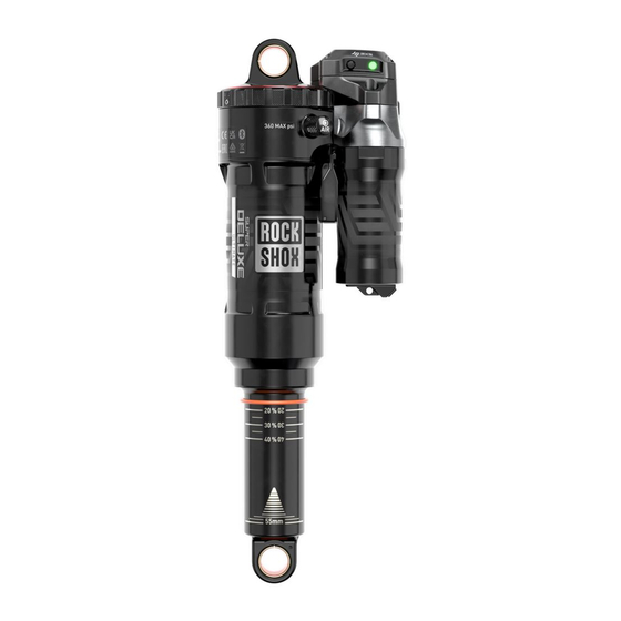
Page 8: Rear Shock Module
Rear Shock Module a. Rear Shock Module c. AXS button (Pairing, Battery Check) e. Battery latch b. LED indicator d. SRAM battery f. Battery block Pedal Sensor a. Seal tube (non-threaded) d. LED indicator g. Expander wedge/bolt assembly b. Seal tube (threaded) e. -
Page 9: Rockshox Axs Controller
Battery cover e. Mount plug screw h. LED indicator c. MatchMaker X (MMX) clamp f. Clamp bolt holes SRAM AXS Rocker Controller a. Rocker paddle d. AXS Controller discrete clamp g. AXS button (Pairing, Battery Check) b. Battery cover e. -
Page 10: Batteries
Do not use sharp objects to remove the batteries. Component Batteries The AXS Controller (A) and Pedal Sensor (C) batteries are pre-installed. The SRAM batteries (B) are included separately and must be fully charged before installation and use. NOTI CE If the AXS Controller coin cell battery is depleted, activating Flight Attendant, or any other paired AXS component, with the AXS Controller is not possible until the battery is replaced. -
Page 11: Battery Charge Led Indicator
The AXS component LED indicators illuminate when the component AXS button is pressed. The color of the LED indicates the battery charge level. During use, if a Flight Attendant suspension component has a blinking red LED, the battery must be recharged or replaced. Battery levels can also be checked in the SRAM AXS app. 6-26 months 1-6 months <1 month... -
Page 12: Sram Battery Charging
SRAM Battery Charging Remove the battery cover from each SRAM battery and charge both N OTI CE batteries. Do not discard the battery cover. To protect the battery terminals, Consult the SRAM Battery and Charger User Manual at install the battery cover on the battery when it is not on the www.sram.com/service... - Page 13 Insert the fully charged SRAM battery into the module and close the battery latch. When installed correctly, the latch will snap into place. Install Adjust...
-
Page 14: Controller Installation - Optional
Controller Installation - Optional AXS Controller - MMX Clamp 5.5 N·m (49 in-lb) 3 N·m (27 in-lb) 3 N·m (27 in-lb) 2 N·m (18 in-lb) Friction Paste Install Torque Remove/Loosen Adjust... -
Page 15: Axs Controller - Discrete Clamp
AXS Controller - Discrete Clamp 2 N·m (18 in-lb) 3 N·m (27 in-lb) 2 N·m (18 in-lb) Friction Paste Install Remove/Loosen Adjust Torque... -
Page 16: Flight Attendant Setup
Flight Attendant Setup Component Serial Number Identification Locate and record the AXS serial number on the Flight Attendant Control Module. The serial number can be used in the AXS app to identify the Flight Attendant Control Module. All paired components in the system will be linked to the Control Module. Setup Process After all components and fully charged batteries have been installed, 1. -
Page 17: System Pairing
Additional AXS components can be paired with Flight Attendant to create one AXS system. After multiple AXS components have been paired into one system, functions and preferences can be configured in the SRAM AXS app. If pairing Flight Attendant components only, Press and hold the AXS button on the Control... - Page 18 Module to end the pairing session, or wait 30 seconds for the session to time out. The AXS LED will stop blinking. Successful pairing can be verified with the SRAM AXS app. All paired The pairing process does not need to be repeated when any battery components will be listed below the Flight Attendant Control Module.
-
Page 19: Multi-System Pairing Options
Multi-System Pairing Options To pair additional AXS components (AXS rear derailleur, Reverb AXS) into one AXS system, begin and end pairing with the Flight Attendant Control Module. Flight Attendant and AXS components can be paired in any order after beginning with the Flight Attendant Control Module. Pictured is a multi-system pairing example beginning (1) and ending (8) with the Flight Attendant Control Module. -
Page 20: Spring Air Pressure And Rebound Damping
Spring Air Pressure and Rebound Damping Spring air pressure, which affects system Calibration and suspension performance, is set in the same manner as traditional suspension components, and must be set before system Calibration. Rebound damping can be set and adjusted at any time. Manual Mode is the active default mode for a new Flight Attendant system. -
Page 21: Calibrate The System
Calibrate the System To ensure the system is set up correctly for the bicycle, Flight Attendant must be calibrated once per bicycle installation or component replacement, and before the bicycle is ridden. The system can be calibrated only after all components have been paired, and can be recalibrated at any time after the first system calibration. - Page 22 When the PEDAL LED pulses White slowly, Hold the bicycle 90° vertical and steady. − Press and hold the ( ) and ( ) buttons − release the ( ) and ( ) buttons and continue Do not move the bicycle. simultaneously for 3 seconds.
- Page 23 CALIBRATE TILT: When the OPEN Slowly start to tilt the bicycle toward the Hold the bicycle steady in the tilted position LED pulses White slowly, unweight the non-drive side and hold it steady. with the handlebar straight. suspension and stand over the bicycle. When the OPEN LED blinks White quickly, Tilt Calibration is successful.
- Page 24 Calibration Tilt / Error Indicators Vertical Calibration Tilt Indication (Red LED) During Vertical Calibration, Red LEDs may illuminate indicating that the bicycle is leaned too far in the direction of the Red LED. Tilt the bicycle slowly toward the PEDAL LED until only the PEDAL LED blinks White quickly. Tilt Calibration Tilt Indication (Red LED) During Calibration, Red LEDs may illuminate indicating that the bicycle is leaned too far in the direction of the Red LED.
- Page 25 Calibration Troubleshooting System Time Out (Red LEDs): If Calibration is not successful after 25 seconds during Vertical or Tilt Calibration, the OPEN, PEDAL, and LOCK LEDs will flash Red simultaneously. When the Red LEDs stop flashing, Calibration is canceled and the system will return to the previously active mode.
-
Page 26: Set Bias Adjustment
Higher values bias the system toward firmness and efficiency with an increased likelihood of LOCK. Lower Bias values provide a more OPEN system that is less likely to activate LOCK. Refer to the SRAM AXS app for setting Bias Adjustment level using the app. Bias Adjustment selection must begin from Auto Mode. -
Page 27: Set Low Speed Compression (Lsc)
Set Low Speed Compression (LSC) Set the desired front and rear suspension Low Speed Compression As with standard suspension components, LSC adjustment only (LSC) damper settings. affects OPEN position performance and has no effect on the PEDAL or LOCK settings. LSC settings function independently of Flight Attendant Modes and remain set to the selected settings until changed manually with the LSC can be adjusted from Auto Mode or Manual Mode. -
Page 28: Modes And Settings
Modes and Settings Flight Attendant functions can be selected with the Flight Attendant Control Module Menu button. Functions include Settings and Modes. Modes actuate and adjust suspension position in Auto, Manual, Override, or Safe Mode. Settings are used to select Low Speed Compression (LSC) damper settings, and select suspension Auto Mode Bias Adjustment... - Page 29 Front and rear suspension can be in different suspension positions Two green LEDs will illuminate when different suspension positions in Auto Mode. are active. FRONT SUSPENSION - OPEN FRONT SUSPENSION - OPEN FRONT SUSPENSION - PEDAL REAR SUSPENSION - OPEN REAR SUSPENSION - PEDAL REAR SUSPENSION - PEDAL FRONT SUSPENSION - PEDAL...
-
Page 30: Manual Mode
Manual Mode Manual Mode can only be activated from Suspension air spring settings should be Use the Flight Attendant Control Module − the Flight Attendant Control Module Menu set with the system in Manual Mode, in ) and ( ) buttons, or the AXS Controller if button. -
Page 31: Override Mode
With the AXS Controller, the rider can manually deactivate Auto LOCK is the default Override suspension position. Mode and activate Override Mode which activates a preselected Use the SRAM AXS app to change the Override Mode position from suspension position (OPEN, PEDAL, or LOCK). LOCK to OPEN or PEDAL. -
Page 32: Safe Mode
Safe Mode Toubleshooting If three yellow LEDs are illuminated Safe Mode has been activated. Settings cannot be adjusted in the SRAM AXS app when Safe Mode is activated. Safe Mode cannot be exited until the triggering issue has been resolved. -
Page 33: Operating Flight Attendant
N OTI CE Remove the SRAM batteries and install the battery blocks into the Flight Attendant Control Module and rear shock Module before cleaning. Do not clean the components with a power washer. Do not use acidic or grease-dissolving agents. Do not soak or store Flight Attendant components or the AXS Controller in any cleaning... -
Page 34: Storage And Transportation
N OTI CE Remove the SRAM batteries and install the battery blocks and battery covers when the bicycle is being transported or not in use for long periods of time. Failure to remove the SRAM batteries could result in battery depletion. -
Page 35: Pedal Sensor - Battery And Service
Pedal Sensor - Battery and Service N OTI CE To avoid permanent damage to the Pedal Sensor caused by battery corrosion, ONLY use AAA Lithium/Iron Disulfide (Li/FeS non-rechargeable batteries. Do NOT use rechargeable Lithium (Li-ion), alkaline, or nickel metal hydride (Ni-MH) batteries in the Pedal Sensor. Non-Threaded Pedal Sensor - Removal Loosen the Pedal Sensor bolt (drive side) while pushing the Pedal N OTI CE... -
Page 36: Replace Battery
Replace Battery With the tapered end on a flat soft surface, The seal tube will snap free from the Pedal Remove the seal tube. push down holding the seal tube. Sensor assembly. ⚠ WA RN ING Remove the AAA Lithium/Iron Disulfide Install a new AAA Lithium/Iron Disulfide (Li/FeS ) battery. - Page 37 Clean the o-ring grooves with a damp shop towel. Consult the RockShox Spare Parts Catalog at www.sram.com/service for available spare part kits. Install the Pedal Sensor assembly into the seal tube, align the tabs, and press both pieces together until the tube snaps into place.
-
Page 38: Non-Threaded Pedal Sensor - Installation
Non-Threaded Pedal Sensor - Installation 0.56 N·m (5 in-lb) Install the Pedal Sensor into the non-drive While pressing the end of the Pedal Sensor NOTICE side crank spindle. into the crank with your thumb, tighten To avoid damage to the expander wedge, the expander wedge bolt to the specified do not over tighten the expander wedge torque. -
Page 39: Recycling
Recycling ⚠ WARN IN G Replace the SRAM battery with an authentic For recycling and environmental SRAM battery only. Replace the AXS compliance, please visit www.sram.com/en/ Never dispose of batteries in a fire. Controller battery with a CR2032 coin cell company/about/environmental-policy-and- battery only. - Page 40 Quarq®, RacerMate®, Reba®, Rock Shox®, Ruktion®, Service Course®, ShockWiz®, SID®, Single Digit®, Speed Dial®, Speed Weaponry®, Spinscan®, SRAM®, SRAM APEX®, SRAM EAGLE®, SRAM FORCE®, SRAM RED®, SRAM RIVAL®, Stylo®, TIME®, Truvativ®, TyreWiz®, UDH®, Varicrank®, Velotron®, X0®, X01®, X-SYNC®, XX1®, Zipp®...
- Page 41 ASIAN HEADQUARTERS WORLD HEADQUARTERS EUROPEAN HEADQUARTERS SRAM Taiwan SRAM LLC SRAM Europe No. 1598-8 Chung Shan Road 1000 W. Fulton Market, 4th Floor Paasbosweg 14-16 Shen Kang Hsiang, Taichung City Chicago, Illinois 60607 3862ZS Nijkerk Taiwan R.O.C. U.S.A. The Netherlands...
Need help?
Do you have a question about the RockShox Super Deluxe Flight Attendant and is the answer not in the manual?
Questions and answers