
Subscribe to Our Youtube Channel
Related Manuals for Shimadzu iMLayer


Summary of Contents for Shimadzu iMLayer
- Page 1 ZEBV-5088C Matrix Vapor Deposition System iMLayer Pre-Installation Requirements (Installation Preparations/Confirmation)...
- Page 2 Notice (1) All rights are reserved, including those to reproduce this manual or parts thereof in any form without permission in writing from Shimadzu Corporation. Copyright 2018 Shimadzu Corporation (2) Information in this manual is subject to change without notice and does not represent a commitment on the part of the vendor.
-
Page 3: Table Of Contents
ZEBV-5088C Contents 1. INTRODUCTION ····················································· 3 2. INSTALLATION CONDITIONS ··································· 4 2.1 Carry-in route ................4 2.2 Example installation ..............5 2.3 Wiring and Piping ............... 7 2.4 Ambient Requirements .............. 7 2.5 Required Power Supply ............. 8 3. Customer pre-check list ............ 10... -
Page 4: Introduction
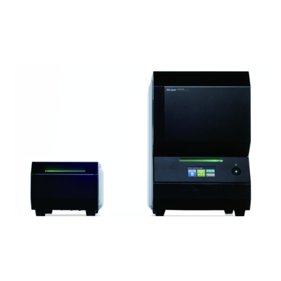
ZEBV-5088C 1. Introduction These Pre-Installation Requirements describe the requirement to facilitate installation of the iMLayer. To keep the instrument stable, please make prior arrangement in accordance with these requirements. They can also be used for routine maintenance. This instrument consists of a main unit used for vapor deposition of the matrix, a deposition power supply used to supply power to the boat for vapor deposit, and a vacuum pump used to evacuate the inside the chamber of iMLayer. -
Page 5: Installation Conditions
The instrument can be carried on a hand truck. Check the following points so that delivery can be carried out without problems. 1) Check that there is no step the passage. 2) When lifting the iMLayer, be sure to wear non-slip gloves and to work by more than two persons. -
Page 6: Example Installation
ZEBV-5088C 2.2 Example Installation (dimensions indicated in mm) Front view (1000) 150 296 Wall 壁 Top view Fig.1 Typical Layout Using a Typical Draft chamber. - Page 7 The rotary pump will be placed on the side of or under the draft chamber on which iMLayer is installed. When placing the rotary pump on the side of the draft chamber, for wiring and piping, ensure a distance of 150 mm or more between the side of the rotary...
-
Page 8: Wiring And Piping
ZEBV-5088C 2.3 Wiring and Piping Connection of power supply, cables, etc. of the iMLayer, is shown in Fig 2. To power supply To evacuation duct Fig 2 iMLayer cable connection Table2 cable connection information Item Description Length(m) number Power supply cable (To the deposition power supply) -
Page 9: Required Power Supply
2.5 Required Power Supply For safety reasons use a power supply equipped with a ground fault interrupter. The iMLayer uses 100 V AC, 15 A, 50/60 Hz (single phase). Avoid sharing power source with other equipment. To avoid electric shock, ensure grounding at power supply ground terminal has a resistance of 100 ohm or less. - Page 10 Brown(L) 100V Black 225-25318-41 Blue(N) CABLE ASSY, IMSCOPE PS2 Earth Terminal (Outside) 225-25317-41 iMLayer To iMScope AC100V in CABLE ASSY, IMSCOPE PS1 To power supply 225-25319-41 CABLE ASSY, IMSCOPE PS3 225-25320-41 CABLE ASSY, IMSCOPE EARTH To protective earth Fig 4 How to install the step- down transformer, TBX - 1.5KVA...
-
Page 11: Customer Pre-Check List
(DD) The sheets on the following pages are a checklist for each of the installation conditions that have been described in this document. Please fill out the checklist yourself and pass it on to the appropriate personnel at Shimadzu. Customer:... - Page 12 ZEBV-5088C Required itme ( * refers to Shimadzu Item Condition Check part number ) 1. Carry-in route ・ The instrument must be movable in the □ building. ・ There is no step in the passage. Temperature 18 to 28°C □...
Need help?
Do you have a question about the iMLayer and is the answer not in the manual?
Questions and answers