
Related Manuals for Shimadzu ICPE-9000


Summary of Contents for Shimadzu ICPE-9000
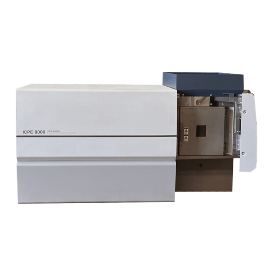
- Page 1 305-34043C Shimadzu Multitype ICP Emission Spectrometer ICPE-9000 Hardware INSTRUCTION MANUAL Read the instruction manual thoroughly before you use the product. Keep this instruction manual for future reference.
- Page 3 Shimadzu representative. • To ensure safe operation, be sure to read "Safety Precautions" before using the product. • Installation is performed by Shimadzu-designated service engineers. To ensure safety, do not perform installation yourself or allow anybody other than a Shimadzu-designated service engineer to perform installation.
- Page 4 Warranty 1. Warranty Period Contact your Shimadzu representative. 2. Scope If a fault that can be attributed to Shimadzu occurs during the warranty period, Shimadzu will repair the product or provide the necessary replacement parts free of charge. 3. Limitations This warranty does not cover faults that can be associated with any of the following: 1) misuse;...
- Page 5 Replacement parts will be available for this product for a period of seven (7) years after its discontinuation. Thereafter, replacement parts may cease to be available. Note, however, that the availability of parts not manufactured by Shimadzu shall be determined by the relevant manufacturers.
- Page 7 Safety Precautions • To ensure safe operation, read these safety precautions thoroughly before using the product. • Be sure to observe all the safety precautions given here. They are extremely important for ensuring safety. • In this manual, precautionary information is indicated using the following conventions. Indicates a potentially hazardous situation which, if not WARNING avoided, could result in death or serious injury.
- Page 8 Safety Precautions Related to Installation Location WARNING • Some of the solvents used for measurement are flammable or toxic. Be sure to ventilate the room properly. Not doing so may result in poisoning or fire. • Organic solvents are sometimes used for measurement. Therefore, do NOT use open flames near the product and do NOT install the product in the same room as equipment that generates sparks.
- Page 9 • Do NOT place heavy objects on, or thermal appliances near, the power cord. Otherwise, the cord may break and cause fire, electric shock, or faulty operation. If the cord is damaged, promptly contact your Shimadzu representative. • Do NOT modify or stretch the power cord, or bend it excessively.
- Page 10 CAUTION • Be careful not to trap your fingers in gaps in the equipment during installation. Otherwise, your fingers may be injured. • Be careful not to trap your fingers when opening and closing doors. Otherwise, your fingers may be injured. Safety Precautions Related to Installation Work WARNING •...
- Page 11 Using a different type of fuse may result or fire. Contact your Shimadzu representative to inquire about fuses not specified in this instruction manual. • If dust adheres to the power plug's pins or pin-side face, remove the power plug and wipe it clean with a dry cloth.
- Page 12 In order to ensure safety, warning labels are attached in places requiring caution. If a warning label is lost or damaged, obtain a new label through your Shimadzu representative and attach it in the correct position. See "Warning Labels on the Equipment" in this instruction manual for details on the positions where the labels are attached.
- Page 13 (3) Plasma Stand Door 037-72122-00 LABEL, WARN, SA40-122P (Japanese) 037-72125-00 LABEL, WARN, SA40-125P (English)
- Page 14 Warning Labels x i i...
- Page 15 WEEE Mark Contact Shimadzu service representative when the equipment has reached the end of its life. They will advise you regarding the equipment take-back. With your co-operation we are aiming to reduce contamination from waste electronic and electrical equipment and preserve natural resource through re-use and recycling.
- Page 16 x i v...
- Page 17 Handling Precautions Thank you for purchasing the Shimadzu ICPE-9000 multitype ICP emission spectrometer. Read the following items before using the product. Handling High-Pressure Gas This product uses argon gas. Read the section entitled "Handling High-Pressure Gas". Use of Radio Frequency (1) As previously communicated, this product uses a radio frequency (27.120 MHz).
- Page 18 11. The contents of this manual are subject to change without prior notice. 12. Contact your Shimadzu representative if you find any errors in this manual. 13. Shimadzu accepts no responsibility for any events that result from the use of this product. x vi...
- Page 19 Handling High-Pressure Gas Thank you for your continuing support of Shimadzu Corporation products. Many of our products require the use of high-pressure gas. We trust you are already aware of the increasing demand for more stringent levels of safety management with regard to these gases. Although we trust you are already implementing the items listed below, we ask that you review these items and exercise the utmost care in the handling of high-pressure gases.
- Page 20 x vi i i...
-
Page 21: Table Of Contents
CONTENTS 1 . I .................... 1-1 N T R O D U C T I O N 2 . P ....................... 2-1 AR T S 3 . P ..............3-1 R E P AR AT I O N F O R N S T AL L AT I O N 3 . - Page 22 5 . 9 V ..................5-7 AC U U M Y S T E M 5 . 1 0 C .................. 5-8 O O L I N G Y S T E M 5 . 1 1 A ................5-8 R G O N Y S T E M 5 .
- Page 23 7 . 1 . 3 S t o p p i n g t h e I C P E - 9 0 0 0 i n D a i l y U s e ............7 - 3 7 .
- Page 24 8 . 1 7 I ........8-30 N S P E C T I N G T H E R G O N AS AN D O O L AN T I P I N G 8 . 1 8 C ) 8 - 3 0 L E AN I N G T H E I L T E R F O R T H E...
-
Page 25: Introduction
The vacuum-type echelle spectrometer, the two-dimensional semiconductor detector, the photometry system, the ICP RF power supply, and the analysis software were all developed by Shimadzu. The combination of an echelle spectrometer and a two-dimensional detector brings many advantages. For example, the simultaneous analysis of multiple elements reduces analysis time, the use of a mini-torch reduces running costs, and axial-view plasma observation increases sensitivity. - Page 26 1 Introduction 1 - 2...
-
Page 27: Parts
2 Parts 2. Parts The standard ICPE-9000 package consists of the following parts. Check that they are all included. Part number Part name Qty. Notes 211-86003-91 ICPE-9000, BODY ASSY Main unit 016-31404 VINYL T, R3603, 1/8X1/16 For connecting torch (auxiliary gas) and... - Page 28 2.5m Leveler exhaust tube 211-83697 CONNECTION TUBE For connecting autosampler suction tube 211-86547 PLATE, TUBE HOLDER Tube hook on right side of ICPE-9000 211-86136-91 TUBE BAND ASSY Block for securing tube on right side of ICPE-9000 MOLECULAR SIEVE Vacuum system...
-
Page 29: P R E P Ar At I O N F O R I
3. Preparation for Installation 3.1 Installation Environment Before installing the ICPE-9000, the laboratory must be prepared as described in the ICPS-9000 installation guidelines provided separately. Check the following items before installation. (1) The position of the plasma stand exhaust duct and the exhaust capacity must be appropriate. A damper must also be provided. -
Page 30: I N S T Al L I N G An D
3 Preparation for Installation 3.2 Installing and Handling the Data Processing Unit General points to note regarding the installation and handling of the data processing unit are given below. 3.2.1 Operating Environment and Storage (1) Do not install the unit in a location where the display screen will be directly exposed to sunlight or light emitted by lighting fixtures in the ceiling. -
Page 31: R I N C I P L E S
4 Basic Principles 4. Basic Principles ICP (inductively coupled plasma) emission spectrometry is a method used to perform emission spectrometry using inductively coupled plasma as the light source. In order to facilitate a deeper understanding of ICP analysis, this section describes the fundamentals of measurement performed with emission spectrometry. -
Page 32: Intensity Method (Time Integration Method) And Intensity Ratio Method
4 Basic Principles 4.1.3 Intensity Method (Time Integration Method) and Intensity Ratio Method (Internal Standard Method) A calibration curve is created by obtaining the emission intensities of multiple standard samples with different concentrations by integrating over a fixed time period, plotting the results on a graph with concentration represented by the horizontal axis and emission intensity represented by the vertical axis, and obtaining a relationship in terms of linear, quadratic, and higher-order expressions. -
Page 33: P L As M A
4 Basic Principles 4.2 Fundamentals, Principles, and Characteristics of Inductively Coupled Plasma 4.2.1 Definition of Plasma In the field of physics, an American physical chemist Langmuir in the 1920's gave the name "plasma" to a region where electric charges of ions and electrons are balanced. This was the first time for the word plasma appeared in this field. -
Page 34: Features Of Icp
4 Basic Principles 4.2.3 Features of ICP (1) The introduction of a solution sample makes it easier to prepare a standard sample as compared with a solid sample. It also improves the analysis accuracy. (2) Extremely high sensitivity and a low detection limit to various elements are realized. (3) Very few chemical interference as occurred with the conventional flame (chemical flame) due to high plasma temperature and a doughnut- shaped hole where a sample is placed for a comparatively long time. -
Page 35: F U N D Am E N T Al S O F
4 Basic Principles 4.3 Fundamentals of Spectrometers The spectrometers used for emission spectrometry must be able to separate very large numbers of atomic spectral lines and must therefore have greater resolution than the spectrometers used for atomic absorption spectrometry. A diffraction grating is used as the spectrometer's dispersive element. This is because relatively large diffraction gratings can be produced, making it possible to create bright spectrometers, and also because they enable the creation of spectrometers that attain a high resolving power, either by having a large number of grooves (e.g., sequential ICP spectrometers) or by using higher order spectra (e.g., echelle ICP... -
Page 36: Mounting Of Spectrometer
Schmidt mirror, and an image is formed by the telemeter mirror at the exit slit. With the ICPE-9000, a two-dimensional semiconductor detector is used instead of an exit slit. -
Page 37: Detector
Semiconductor detectors come in CCD (charge coupled device) and CID (charge injection device) types. Repeated reading is possible with a CID but all the pixels are read in one operation with a CCD. The ICPE-9000 uses a CCD. The sensitivity of a photomultiplier tube is adjusted by changing the applied voltage. With a semiconductor detector, however, the sensitivity adjustment is not possible for individual pixels. -
Page 38: Outline
4 Basic Principles 4.5 Principle of RF Power Supply 4.5.1 Outline The energy used to generate ICP is applied to the plasma in the form of RF electric power. This RF electric power is generated by an RF power supply, which is configured as shown in "Fig. 4-4". Plasma Coaxial cable Matching... -
Page 39: C O N F I G U R At I O N An D
5 Configuration and Operating Principle of the ICPE-9000 5. Configuration and Operating Principle of the ICPE-9000 5.1 Block Diagram Data processing unit: Computer CPU for hardware control Controller Spectrometer temperature adjustment Spectrometer vacuum system CCD detector Peristaltic pump RF power supply... - Page 40 LAN terminal Controller Vacuum system Waste tank (Table and waste tank not provided.) Fig. 5-2 Appearance of ICPE-9000 NOTE Do NOT install the ICPE-9000 in a position where it is difficult to turn OFF the power switch. 5 - 2...
- Page 41 5 Configuration and Operating Principle of the ICPE-9000 5.3 External Connection of Power Supply, Argon Gas, and Coolant The ICPE-9000 requires a single-phase, 200/220/230/240-V, 50/60-Hz, 30-A power supply, a ground, argon gas, and coolant. The coolant is used to cool the cooling jacket, the RF coil, and the CCD. The coolant for the cooling jacket and the RF coil is provided from the same system.
- Page 42 5 Configuration and Operating Principle of the ICPE-9000 Coolant inlet for RF coil and cooling jacket CCD coolant pumping signal connector Coolant outlet for RF coil and Argon gas inlet cooling jacket Ground cable CCD coolant inlet Power cable CCD coolant outlet Fig.
- Page 43 Fig. 5-5 Piping and Wiring for CCD Cooling water circulation system (Option) 5.4 Connecting the Data Processing Unit to the ICPE-9000 Connect the ICPE-9000 LAN terminal and the LAN card terminal on the data processing unit with the LAN cable provided. (See "Fig. 5-3".)
- Page 44 5 Configuration and Operating Principle of the ICPE-9000 5.5 Spectrometer and Light-Focusing System In axial-view observation, light from the ICP is bent 90° by the back-reflect mirror in the cooling jacket, it passes through the glass window in the section joining the spectrometer and the cooling jacket, and it is reflected by the toroidal mirror and the plane mirror to form an image at the entrance slit.
-
Page 45: Ccd Detector
(e.g., higher than 28°C). ICPE-9000 performance is greatly affected by the stability of the spectrometer temperature. Therefore, do not turn OFF the power supply to the main unit under normal circumstances as this will also turn OFF temperature control. -
Page 46: O O L I N G S Y S T E M
The argon gas passes through an in-line filter before entering the ICPE-9000. The gas pressure at the ICPE-9000 inlet (argon gas inlet shown in "Fig. 5-4") is set in the range 450±10 kPa. If the pressure is less than 300 kPa, the pressure sensor detects this and automatically extinguishes the plasma. -
Page 47: Sam P L E I N T R O D U C T I O N S Y S T E M
5 Configuration and Operating Principle of the ICPE-9000 5.12 Sample Introduction System (Including Plasma Stand Interior) "Fig. 5-7" shows the plasma light source. The parts are shown in "Fig. 5-8" and "Fig. 5-9". WARNING Risk of Burn Injury There is a risk of burn injury. When checking the plasma stand, do NOT touch the plasma stand interior for 3 minutes after the plasma is extinguished. - Page 48 5 Configuration and Operating Principle of the ICPE-9000 The plasma torch is made of quartz and has a threefold structure in which plasma gas (coolant gas), auxiliary gas, and carrier gas flow (from the outside). (2) Plasma gas For the plasma gas (coolant gas), argon gas is delivered at a standard rate of 8 to 10 L/min.
-
Page 49: (Plasma Stand Interior)
5 Configuration and Operating Principle of the ICPE-9000 Purge gas Cooling jacket Optical fiber photoelectric switch Orifice ASSY L RF coil Plasma torch Igniter cable Plasma gas tube ASSY Auxiliary gas tube Extension pipe Chamber Leveler Nebulizer Sample introduction tube Carrier gas tube Fig. - Page 50 5 Configuration and Operating Principle of the ICPE-9000 (12) Leveler Drain Tube Drains the waste from the leveler to the waste tank. (13) Condensation Drain Tube Condensation flows into the condensation collector when condensation occurs inside the instrument. (14) Leveler Exhaust Tube Draws the gas given off by the sample in the leveler to the exhaust duct.
-
Page 51: Jac K E T
5 Configuration and Operating Principle of the ICPE-9000 5.13 Cooling Jacket In axial-view observation, the plasma makes contact with the cooling jacket. The cooling jacket is cooled with water and prevents damage to the orifice and the emission of light by the metal elements that make up the orifice. -
Page 52: Rad I Al
5 Configuration and Operating Principle of the ICPE-9000 5.14 Radial-View Observation Kit (Option) This optional unit is installed inside the plasma stand and enables radial-view observation. Switching between axial-view observation and radial-view observation is possible from the software. The observation points at the top and bottom set in radial-view observation can also be switched from the software. - Page 53 5 Configuration and Operating Principle of the ICPE-9000 (1) Switching Observation Direction The observation direction is switched using the software. When igniting the plasma, perform the switching operation from the software's [Instrument Control] window and check that the observation direction has been switched properly. The mark shown below is displayed in the observation direction indicator.
- Page 54 5 Configuration and Operating Principle of the ICPE-9000 Entrance window cover locking screw Entrance window cover Fig. 5-12 Entrance Window Cover Entrance window Back-surface mirror Spectrometer inside cooling jacket (vacuum) Fig. 5-13 Cooling Jacket Optical System with Radial-View Observation Kit (Option) Attached...
- Page 55 5 Configuration and Operating Principle of the ICPE-9000 Spectrometer Interior (vacuum) Reflective mirrors for radial-view observation Entrance window Fig. 5-14 Optical System for Radial-View Observation with Radial-View Observation Kit (Option) Attached 5 - 1 7...
-
Page 56: Lis T S O F M A In T E N A N C E P A R T S A N D C O N S U M A B Le I T E M S F O R R A D Ia L- V Ie W
5 Configuration and Operating Principle of the ICPE-9000 5.14.1 Lists of Maintenance Parts and Consumable Items for Radial-View Observation Kit Maintenance Parts List Part name Notes 036-10202 O-RING, 1A P4 O-ring for shaft 036-10218 O-RING, 1A P18 O-ring axial-view observation... - Page 57 5 Configuration and Operating Principle of the ICPE-9000 Consumable Items List Part name Notes Quartz tube for purge in radial 211-86218-91 PURGE PIPE, ADHESIVE direction 211-84356 BONNET,STD TORCH 5 - 1 9...
-
Page 58: F P O W E R S U P P L Y
5 Configuration and Operating Principle of the ICPE-9000 5.15 RF Power Supply The RF power supply includes the output unit, which is configured with transistors, the matching circuits for the output unit and the RF coil, and control system for external control. This power supply is designed specifically for use with plasma and improved for the use of digital control instead of analog control. - Page 59 5.16 Purpose and Operating Principles of Safety Devices The ICPE-9000 incorporates the following safety devices: a temperature fuse in the plasma stand, a plasma stand door switch, a coolant flow switch, a temperature fuse in the RF power supply, an argon gas pressure switch, a photoelectric switch, and a CCD condensation sensor.
- Page 60 5 Configuration and Operating Principle of the ICPE-9000 The CCD detector is cooled at a water temperature of approx. 10°C. If the water temperature is too low or if the humidity level of the installation location is too high, condensation may occur on the internal radiator plate and possibly result in damage to the CCD.
-
Page 61: O N N E C T O R Pan E L
5 Configuration and Operating Principle of the ICPE-9000 5.17 Connector Panel The connector panel is used to connect to optional units. * PUMP Terminal used to connect to a peristaltic pump (option). * ASC Terminal used to connect to the ASC-6100F autosampler (option). -
Page 62: S C - 6 1 0 0 F A U T O S Am P L E R
ICPE-9000's connector panel. (See "5.17 Connector Panel".) (2) Connect the nebulizer's sample introduction tube (see "Fig. 5-8") and the autosampler's suction tube to the connection tube (P/N 211-83687) provided with the ICPE-9000. Cut the nebulizer's sample introduction tube and the autosampler's suction tube to appropriate lengths before connecting them. - Page 63 5 Configuration and Operating Principle of the ICPE-9000 5.19 Optional Plasma Torch and Orifice Assembly If axial view observations are performed using the optional plasma torch (P/N 204-70272) or high TDS torch (P/N 204-77296), the optional orifice assembly (P/N 211-43740) is required. Replace the orifice assembly L attached to the cooling jacket with the orifice assembly (P/N 211-43740).
- Page 64 5 Configuration and Operating Principle of the ICPE-9000 5 - 2 6...
-
Page 65: Specifications
6 Specifications 6. Specifications 6.1 Plasma Light Source (1) Torch unit Axial-view observation with argon gas purge function (2) Spray chamber Cyclone chamber made of Pyrex glass Plasma torch Mini-torch made of quartz Nebulizer Coaxial type made of Pyrex glass (3) RF power matching system Automatic matching (4) Gas controller... -
Page 66: Dat A P R O C E S S I N G U N I T S O F T W Ar E
6 Specifications 6.5 Data Processing Unit Software: ICPEsolution 6.5.1 Measurement Samples 1 data file, 300 samples max. 6.5.2 Qualitative Analysis Analysis using internal database Automatic selection of qualitative-analysis wavelength for each sample Database correction function 6.5.3 Quantitative Analysis: Calibration Curve Method / Standard Addition Method Measurement wavelength: Possible to set multiple measurement wavelengths for each element Automatic selection of quantitative-analysis wavelength for each sample... -
Page 67: User Support
6 Specifications 6.5.4 User Support Development assistant Diagnosis assistant 6.5.5 Instrument Control Monitor display of instrument status Control of vacuum pump Automatic igniting/extinguishing of plasma Automatic extinguish function that operates when analysis completed Automatic control of autosampler 6.6 Utilities 6.6.1 Power Supply Requirements Single phase,200/220/230/240 V ±10% (upper limit: 250 V), 50/60 Hz, 30 A 6.6.2 Ground 30 Ω... - Page 68 6 Specifications Peristaltic pump Hydride generator NOTE The PC used for data processing with the ICPE-9000 must satisfy the following specifications. 1) CPU Intel® Celeron D300 2.66 GHz min. or equivalent 2) RAM 768 MB min. 3) HDD 80 GB min.
-
Page 69: Operation
7 Operation 7. Operation This section describes the procedures used to start and stop the ICPE-9000. Refer to the software instruction manual for details on the analysis operations. 7.1 Starting the ICPE-9000 7.1.1 Starting the ICPE-9000 at Installation (1) Connect the main unit and the PC with the LAN cable. - Page 70 [Instrument] menu, and click [OK].) If the same error re-appears, replace the molecular sieve. (See 8.12 Replacing the Molecular Sieve (Oil Absorbent) in the Vacuum Pump) If the error continues to occur, please contact your Shimadzu representative. 7 - 2...
-
Page 71: Stopping The Icpe-9000 In Daily Use
7 Operation 7.1.3 Stopping the ICPE-9000 in Daily Use (1) Quit the software. (2) Stop the supply of coolant. (3) Turn OFF the printer power switch. (4) Turn OFF the monitor power switch. (5) Turn OFF the computer power switch. -
Page 72: Leak Valve Operation (After Vacuum Pump Is Stopped)
7 Operation 7.1.4 Leak Valve Operation (After vacuum pump is stopped) NOTE When stopping the vacuum pump, release the molecular sieve case to atmospheereic pressure. (1) After stopping the vacuum pump, open the leak valve. (Viewed from above, turn the valve counter-clockwise 2 complete turns.) (2) After the air-leak sound disappears, close the leak valve. -
Page 73: Checking Operation Of Safety Devices
ICPE-9000 in the usual way, turn OFF the ICPE-9000's power switch. The power supplied to the ICPE-9000 is interrupted. Stop the supply of argon gas to the ICPE-9000 by closing the main valve of the argon gas supply. Stop the supply of coolant to the ICPE-9000. - Page 74 7 Operation 7 - 6...
-
Page 75: Maintenance
8 Maintenance 8. Maintenance NOTE Extinguish the plasma at least once a day to perform, for example, maintenance of the glassware and to check that there is no condensation on the parts. 8.1 Replacing and Inspecting Glassware The glassware inside the ICP stand must sometimes be cleaned or replaced. The approximate replacement period and the replacement procedure are given below. -
Page 76: Nebulizer
8 Maintenance 8.1.2 Nebulizer Deposits adhere to the tip of the nebulizer when analyzing alkali solvents. Be sure to use a water bubbler (option) when analyzing this kind of sample. If there is clogging in the tip of the nebulizer, the sample suction speed may reduce significantly and sample suction may even stop. -
Page 77: Removing Glass Parts
8 Maintenance 8.2 Removing Glass Parts WARNING Risk of Burn Injury There is a risk of burn injury. Do NOT touch the plasma stand interior for 3 minutes after the plasma is extinguished. CAUTION Glass parts break easily and may cause injury if they are damaged. Handle them with care. -
Page 78: Removing The Chamber And Extension Pipe
8 Maintenance 8.2.1 Removing the Chamber and Extension Pipe Extension pipe Fig. 8-2 Removing the Chamber * Remove the ball joint clip that connects the chamber and the extension pipe and remove the chamber. * Remove the ball joint clip that connects the extension pipe and the torch and remove the extension pipe. -
Page 79: Removing The Leveler
8 Maintenance (1) Remove the nebulizer from the chamber. * Hold the part connecting the chamber and the nebulizer with one hand and hold the nebulizer with the other hand. * Pull the nebulizer out of the chamber. (2) Remove the carrier gas tube's clamp. * Slide the clamp's hook up and down to remove it. -
Page 80: Removing The Torch
8 Maintenance * Hold the chamber with one hand and, hold the leveler with the other hand, and pull and turn the chamber to remove the leveler. (4) Remove the liquid in the leveler. (5) Remove the drain tube. * Slide the clamp's hook up and down to remove it. * Hold the part connecting to the leveler drain tube with one hand, hold the drain tube with the other hand, and pull the leveler away from the drain tube. -
Page 81: Attaching The Glassware
8 Maintenance 8.3 Attaching the Glassware CAUTION Glass parts break easily and may cause injury if they are damaged. Handle them with care. 8.3.1 Attaching the Torch (1) Connect the igniter cable to the auxiliary gas inlet of the torch. (2) Push the igniter cable through the hole shown in Fig. - Page 82 8 Maintenance (3) Insert the plasma gas tube assembly and the auxiliary gas tube in the torch. * Insert approx. 10 mm of plasma gas tube assembly into the plasma gas inlet of the torch. * Insert approx. 10 mm of tube into the auxiliary gas inlet of the torch. * Attach the Teflon ring at a position 46 mm from the end of the torch.
- Page 83 8 Maintenance Torch position adjustment jig Torch mount Insert the igniter cable terminal in the auxiliary gas inlet. Position of gap in Teflon ring Fig. 8-8 Attaching the Torch (6) Remove the torch position adjustment jig and return it to the original position. At this time, pull the chain protruding from the torch position adjustment jig outside the plasma stand door.
- Page 84 8 Maintenance 8.3.2 Attaching the Leveler (1) Attach the drain tube. * Insert approx. 20mm of drain tube into the bottom end of the leveler. * Secure the drain tube with the clamp. (2) Attach the leveler to the chamber. * Insert the leveler into the bottom end of the chamber.
-
Page 85: A T T A C H I N G T H E N E B U L I Ze
8 Maintenance 8.3.3 Attaching the Nebulizer (1) Attach the carrier gas tube. * Hold the nebulizer's carrier gas inlet with one hand and, with the other hand, insert approx. 10 mm of the carrier gas tube into the carrier gas inlet. * Attach the clamp. - Page 86 8 Maintenance 8.3.5 Attaching the Chamber (1) Join the ball joint of the torch and the extension pipe, and secure the connection with the ball joint clip. (2) Join the ball joint of the extension pipe and the chamber, and secure the connection with the ball joint clip.
-
Page 87: Replacing The Sample Introduction Tube
8 Maintenance 8.4 Replacing the Sample Introduction Tube The sample introduction tube, the sample introduction tube's nebulizer insertion port, and the drain tube are affected by sample solvents. This may cause liquid leakage or instability in sample suction. In this case, replace the sample introduction tube. - Page 88 8 Maintenance it into the waste tank. (4) Connect the new drain tube to the leveler as described in "8.2.3 Removing the Leveler". (5) Insert the drain tube into the tube hook. Ensure that there is no slack in the drain tube between the leveler and the tube hook.
- Page 89 8 Maintenance 8.6 Replacing the Leveler Exhaust Tube (1) Pull the leveler exhaust tube out of the leveler. (See "Fig. 8-14".) (2) Remove the exhaust tube from the tube hook and the tube-holding block. (3) Remove the leveler exhaust tube from the holding bands on the duct. (4) Remove the leveler exhaust tube from the holding bands on the rear side.
-
Page 90: C L E An I N G An D R E P L Ac E M E N T O F R E F L E C T M I R R O R I N C O O L I N G Jac K E
8 Maintenance 8.7 Cleaning and Replacement of Reflect Mirror in Cooling Jacket WARNING Risk of Burn Injury There is a risk of burn injury. Do NOT touch the plasma stand interior for 3 minutes after the plasma is extinguished. Set screws Do not touch these four screws Fig. - Page 91 8 Maintenance This surface makes contact This surface makes contact with front Fig. 8-18 Attaching Mirror Holder (1) Loosen the mirror holder's set screws and remove the mirror holder from the jacket. Do not remove the mirror from the mirror holder when cleaning it. (2) Clean the mirror attached to the mirror holder using a piece of gauze moistened with alcohol.
-
Page 92: C L E An I N G T H E A X I Al
8 Maintenance 8.8 Cleaning the Axial-View Observation Orifice Assembly L WARNING Risk of Burn Injury There is a risk of burn injury. Do NOT touch the plasma stand interior for 3 minutes after the plasma is extinguished. NOTE Cleaning the orifice assembly L helps prevent sample contamination and abnormal electric discharge. -
Page 93: Attaching And Removing The Cooling Jacket
8 Maintenance NOTE Do NOT perform ultrasonic cleaning on the orifice assembly L. (3) Attach the orifice assembly L. 1) Attach the orifice assembly L to the cooling jacket by turning it manually. 2) Tighten the assembly with a spanner. Be careful not to tighten with excessive force. Contact surface for cooling jacket... - Page 94 8 Maintenance Remove the water-cooled tubes Fig. 8-21 Removing the Water-Cooled Tubes Remove the argon gas purge tube Fig. 8-22 Removing the Argon Gas Purge Tube 8 - 2 0...
- Page 95 8 Maintenance Attachment screws Entrance window Fig. 8-23 Removing the Cooling Jacket Attach the cooling jacket using the following procedure. (1) Insert the upper positioning pin in the cooling jacket's pin hole and turn the jacket slightly in a clockwise direction until the lower positioning pin makes contact with the bottom of the cooling jacket.
-
Page 96: L E An I N G T H E E N T R An C E W I N D O W
8 Maintenance 8.10 Cleaning the Entrance Window If the ICPE-9000 is used for a long time, the surface of the entrance window becomes dirty and the transmittance decreases. Although the appropriate frequency varies with the types of sample analyzed and the frequency of use, cleaning is required at least once every one to two weeks. -
Page 97: Rad I Al
8 Maintenance Radial-axis purge tube Purge tube screws (2 places) Fig. 8-25 Cleaning the Entrance Window NOTE The area on the spectrometer side of the entrance window is maintained in a vacuum state. Do NOT remove the entrance window. 8 - 2 3... - Page 98 8 Maintenance 8.12 Replacing the Molecular Sieve (Oil Absorbent) in the Vacuum Pump The molecular sieve in the vacuum pump at the back of the ICPE-9000 can be replaced while maintaining a vacuum state in the spectrometer. Replace the molecular sieve using the following procedure.
-
Page 99: E P L Ac I N G T H E Vac U U M P U M P O I L
8 Maintenance 8.13 Replacing the Vacuum Pump Oil Inlet (attach oil filter) Oil inlet Exhaust outlet Oil gauge Power switch Drain plug Fig. 8-27 Replacing the Vacuum Pump Oil Replace the pump oil once every six months. Before taking out the oil, warm it up by running the pump for a short while. CAUTION The rotary pump weighs approx. -
Page 100: Waste Tank
Dispose of waste in accordance with your country's laws and regulations. 8.15 Cleaning the Fan Filters The filters on the left side and the bottom of the ICPE-9000 must be cleaned on a regular basis. Clean the filters once every three months. The cleaning methods are described below. - Page 101 8 Maintenance NOTE If the power switch is turned OFF, the spectrometer temperature-control circuit stops operating. The time required for the spectrometer to stabilize varies with the external temperature but, if it has been OFF for 1 to 2 hours, 6 hours is required. It soon recovers, however, after a momentary power interruption.
- Page 102 (2) Slide the filter-restraining bar at the bottom of the right side of the ICPE-9000 to the left. (The bar is in the pouch at the bottom of the ICPE-9000. Hook a finger onto the bar and slide it.) (3) Remove the filter.
- Page 103 8 Maintenance (6) Re-engage the bar onto the pouch-like section at the bottom of the right side of the ICPE-9000. (7) Turn ON the power switch. NOTE If the power switch is turned OFF, the spectrometer temperature-control circuit stops operating. The time required for the spectrometer to stabilize varies with the external temperature but, if it has been OFF for 1 to 2 hours, 6 hours is required.
- Page 104 8 Maintenance 8.17 Inspecting the Argon Gas and Coolant Piping Inspect the argon gas and coolant piping on a regular basis to ensure that there are no leaks. Also, if condensation occurs on the utility connections, place the condensation dish (provided) at the position shown in the figure.
- Page 105 8 Maintenance (5) Open the main valve for the mains water supply. (6) In the [Instrument Control] window, set the [Coolant Water Valve] to [OFF], and click [Apply]. (7) Check that there are no water leaks. (8) Close the main valve for the mains water supply. 8 - 3 1...
- Page 106 8 Maintenance 8 - 3 2...
- Page 107 9 Maintenance Parts and Consumable Items 9. Maintenance Parts and Consumable Items 9.1 Maintenance Parts List Part name Unit Notes 211-86285 SEAL, LINE Exterior part Front panel 211-86282 SEAL, DOOR Exterior part Plasma stand front panel 211-81444 TORCH ADAPTER Accessory Made of Teflon 211-86093-91 TORCH POSITIN JIG ASSY Accessory...
- Page 108 9 Maintenance Parts and Consumable Items Part name Unit Notes 035-57503-11 UNION, TIGHTENING, B-400-61 Gas piping part Ar gas inlet 260-13500-04 HOSE CONNECTOR, Water piping part Coolant inlet /outlet AMC-04 B409 035-65348-04 TEE, UNION, UT4N6X4 Water piping part Flow switch part 016-35757-02 TUBE, N2-4-6X4, RED Water piping part Coil/cooling jacket outlet (*1)
- Page 109 9 Maintenance Parts and Consumable Items Part name Unit Notes 211-88153-92 VALVE, VSO ASSY 9 Gas controller Proportional solenoid valve for plasma gas (cooling gas) 211-88153-93 VALVE, VSO ASSY 10 Gas controller Proportional solenoid valve for auxiliary gas 211-86162-91 MAINTENANCE PART, Gas controller Sensor for gauge SENSOR FOR GAUGE...
- Page 110 9 Maintenance Parts and Consumable Items Part name Unit Notes 018-17101-15 SHIELD, FINGER, 97-611-02 Plasma stand Shield on inner door (406mm unit) 072-60381-02 CLAMP, ULM-18MSG Plasma stand For securing back of leveler exhaust tube 072-60342-04 CLAMP, KCA-64 Plasma stand For securing leveler exhaust tube duct 211-86136-91 TUBE BAND ASSY Plasma stand...
- Page 111 9 Maintenance Parts and Consumable Items Part name Unit Notes 211-86131-95 ADHERED ASSY PRISM Optical part In spectrometer 210-21018 VARIABLE CAPACITOR Matching box/RF Air variable capacitor Power supply 055-87826-17 CAPACITOR,HT50V500KA Matching box/RF 500-pF fixed capacitor Power supply 055-87826-21 CAPACITOR ,HT57V250KA Matching box/RF 250-pF fixed capacitor Power supply...
- Page 112 9 Maintenance Parts and Consumable Items Part name Unit Notes 211-86090-92 CCD SEALING ASSY CCD peripheral part CCD main body 211-86513 INSULATOR, CCD, CCD peripheral part On the spectrometer under BANK OF WATER 211-88027-01 TUBE, CCD, PURGE, 66X1 CCD peripheral part Purge gas shield tube in front of CCD 211-88186-91 CABLE, CTRL PCB-CCD_1M CCD peripheral part Signal cable...
- Page 113 SI GREASE, HIVAC-G 50G 6 months Vacuum system 211-83697 CONNECTION TUBE 1 month (*2) For connecting autosampler suction tube *1: Varies with the ICPE-9000 installation environment. *2: Varies with the analysis samples. *3: Please order it by a meter unit. 9 - 7...
- Page 114 9 Maintenance Parts and Consumable Items 9 - 8...
- Page 115 The leveler was damaged and drain liquid does not accumulate. The spectral intensity is unstable. The ICPE-9000 installation location does not meet requirements related to installation location or facilities. One of the causes listed for problem 1 A large amount of exhaust is discharged from the exhaust duct.
- Page 116 The torch is dirty. The chamber is dirty. The rinse time is short. If the problem is not resolved by performing the appropriate countermeasures, make a note of the problem and contact your Shimadzu representative. 1 0 - 2...
Need help?
Do you have a question about the ICPE-9000 and is the answer not in the manual?
Questions and answers