Sign In
Upload
Download
Table of Contents
Contents
Add to my manuals
Delete from my manuals
Share
URL of this page:
HTML Link:
Bookmark this page
Add
Manual will be automatically added to "My Manuals"
Print this page
×
Bookmark added
×
Added to my manuals
Manuals
Brands
Shimadzu Manuals
Laboratory Equipment
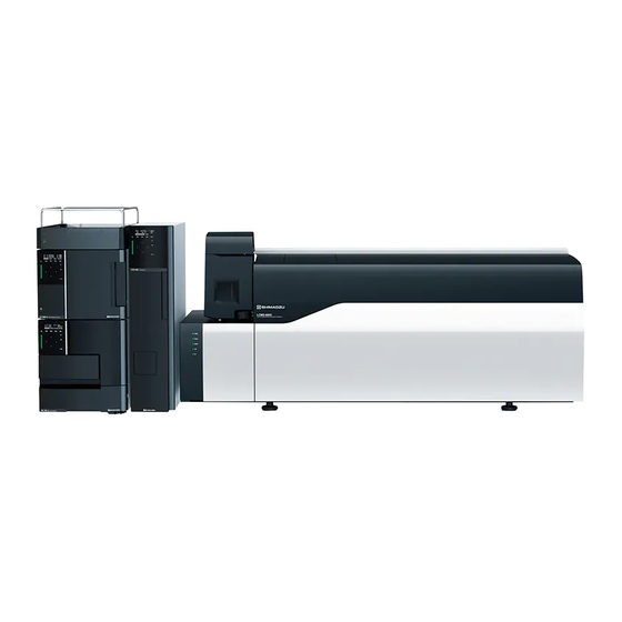
LCMS-8050
Pre-installation requirements manual
Shimadzu LCMS-8050 Pre-Installation Requirements Manual
High-performance liquid chromatograph mass spectrometer
Hide thumbs
1
2
Table Of Contents
3
4
5
6
7
8
9
10
11
12
13
14
15
16
17
18
19
20
21
22
page
of
22
Go
/
22
Contents
Table of Contents
Bookmarks
Table of Contents
Table of Contents
1 Introduction
2 Installation Conditions
Corrosive Gas and Dust
Ventilation and Open Flame Precautions
Electromagnetic Noise
Installation Space
Other Installation Conditions
System Size (Dimensions and Weight)
System Installation Example
Connecting to the Rotary Pump
Connecting to a PC
Required Power Supply
Gas
Nebulizer Gas Drying Gas and Heating Gas
Using a Nitrogen Gas Generator
Using Gas Generated from Centralized Piping (Liquid Nitrogen)
Using a Gas Cylinder
When the Customer Already Has a Nitrogen Gas Generator
CID Gas (Argon Gas)
Evacuation System
Reagents and Mobile Phase
Other Items to be Prepared
Import (Packing Box Size)
Installation to Existing System (HPLC, LCMS)
3 Preliminary Check List
Advertisement
Quick Links
1
Introduction
2
Installation Space
3
Required Power Supply
4
Gas
5
Nebulizer Gas Drying Gas and Heating Gas
6
CID Gas (Argon Gas)
7
Preliminary Check List
Download this manual
ZEBV-5073B
Shimadzu High-Performance Liquid
Chromatograph Mass Spectrometer
LCMS-8050
LCMS-8045
Pre-Installation Requirements
(Installation Preparations/Confirmation)
Table of
Contents
Previous
Page
Next
Page
1
2
3
4
5
Advertisement
Table of Contents
Need help?
Do you have a question about the LCMS-8050 and is the answer not in the manual?
Ask a question
Questions and answers
Related Manuals for Shimadzu LCMS-8050
Laboratory Equipment Shimadzu LC-10 User Manual
(78 pages)
Laboratory Equipment Shimadzu LC-20 User Manual
(78 pages)
Laboratory Equipment Shimadzu LCMS-8045 Pre-Installation Requirements Manual
High-performance liquid chromatograph mass spectrometer (22 pages)
Laboratory Equipment Shimadzu Nexera CL Series Safety Manualline
Liquid chromatograph (42 pages)
Laboratory Equipment Shimadzu LC-40D X3 CL Instruction Manual
(144 pages)
Laboratory Equipment Shimadzu Nexera CL Series System Manual
(338 pages)
Laboratory Equipment Shimadzu FCV-S CL Instruction Manual
Flow channel selection valve for shimadzu liquid chromatograph (50 pages)
Laboratory Equipment Shimadzu GC-2010 Plus Instruction Manual
Gas chromatograph (352 pages)
Laboratory Equipment Shimadzu AOC-20i Manual
(17 pages)
Laboratory Equipment Shimadzu GC17A User Manual
Clarity control module manual (20 pages)
Laboratory Equipment Shimadzu GC-2014 Series Service Manual
(122 pages)
Laboratory Equipment Shimadzu GC-2014 Instruction Manual
Gas chromatograph (318 pages)
Laboratory Equipment Shimadzu GC-2014 Operation Manual
Gas chromatograph (148 pages)
Laboratory Equipment Shimadzu AA-7000 Series Instruction Manual
Atomic absorption spectroscopy (404 pages)
Laboratory Equipment Shimadzu GCMS-QP2010 Series Manual
(13 pages)
Laboratory Equipment Shimadzu GC-2014 Service Manual
(98 pages)
This manual is also suitable for:
Lcms-8045
Table of Contents
Save PDF
Print
Rename the bookmark
Delete bookmark?
Delete from my manuals?
Login
Sign In
OR
Sign in with Facebook
Sign in with Google
Upload manual
Upload from disk
Upload from URL


Need help?
Do you have a question about the LCMS-8050 and is the answer not in the manual?
Questions and answers