Advertisement
Quick Links
VBOX II User Manual
•
01 - VBOX II Front Panel
•
02 - VBOX II SD Cards and Logging
•
03 - VBOX II Display Screen Overview
•
04 - VBOX II VBOX Setup Overview
•
05 - VBOX IISX Single Antenna Placement
•
06 - VBOX 20SL Dual Antenna Placement
•
07 - VBOX 20SL3 Triple Antenna Placement
•
08 - VBOX 20SL Slip/Roll Angle Offsets
•
09 - VBOX II CAN / RS232 / USB
•
10 - VBOX II Smoothing and Filtering
•
11 - VBOX II Digital and Analogue Outputs
•
12 - VBOX II Digital Inputs
•
13 - VBOX II Inputs/Outputs
•
14 - VBOX II Fuse Reset Button
•
15 - VBOX II Technical Properties
•
VBOX II CAN Output
•
VBOX II Dimensions
•
VBOX II PIN OUTS
•
VBOX II Standard Inventory
•
VBOX II Technical Specification
•
VBOX II Firmware Upgrade Procedure
1
Advertisement

Related Manuals for Racelogic VBOX II


Summary of Contents for Racelogic VBOX II
- Page 1 07 - VBOX 20SL3 Triple Antenna Placement • 08 - VBOX 20SL Slip/Roll Angle Offsets • 09 - VBOX II CAN / RS232 / USB • 10 - VBOX II Smoothing and Filtering • 11 - VBOX II Digital and Analogue Outputs •...
- Page 2 01 - VBOX II Front Panel VBOX II units can be configured using the front panel buttons, which enables configuration without the need for a computer. Configuration can also be made via the VBOX Setup Software. From the main screen, press the’■’ button to enter the configuration screen.
- Page 3 Long acc channels, and also Slip, Pitch, Roll, channels on SL units only. OUTPUTS Press ’■’ ’ configure the digital and analogue outputs. Press ’■’ to exit the setup menu and cause the settings EXIT to be saved in EEPROM https://en.racelogic.support//Product_Info/VBOX_Data_Loggers/VBOX_II_Range/VBOX_II_User_Guide/01_-_VBOX_II_Front_Panel...
-
Page 4: Settings Menu
CAN MODE To connect any external CAN modules to the input of the VBOX II RACELOGIC MODULES MODE To connect Racelogic CAN modules to the RLVBOX II (input or output) Press ’■’ to enter the Log Options Menu. LOG OPTIONS In this menu the Logging Mode and Log rate can be set. - Page 5 BACK Press ’■’ to go back to the Main menu. https://en.racelogic.support//Product_Info/VBOX_Data_Loggers/VBOX_II_Range/VBOX_II_User_Guide/01_-_VBOX_II_Front_Panel...
- Page 6 Slip offset can be calculated and applied or cleared. Press ’■’ to enter the Pitch offset sub menu. Within this PITCH OFFSET sub menu a Pitch offset can be calculated and applied or cleared. BACK Press ’■’ to go back to the Main menu. https://en.racelogic.support//Product_Info/VBOX_Data_Loggers/VBOX_II_Range/VBOX_II_User_Guide/01_-_VBOX_II_Front_Panel...
- Page 7 But maximum ROLL or PITCH in this mode should be 10 degrees. Press ’■’ to enter the Roll offset sub menu. Within this ROLL OFFSET sub menu a Roll offset can be calculated and applied or cleared. BACK Press ’■’ to go back to the Main menu. https://en.racelogic.support//Product_Info/VBOX_Data_Loggers/VBOX_II_Range/VBOX_II_User_Guide/01_-_VBOX_II_Front_Panel...
- Page 8 Press ’■’ and then use the ‘◄’ and ‘►’ buttons to ROLL change the amount of smoothing applied to the Roll angle channel. Then press ’■’ to confirm. 0.0 – 5.0 (0.1 steps) BACK Press ’■’ to go back to the Main menu. https://en.racelogic.support//Product_Info/VBOX_Data_Loggers/VBOX_II_Range/VBOX_II_User_Guide/01_-_VBOX_II_Front_Panel...
- Page 9 Only available when output is set to LAT ACC, LONG ACC, PITCH, SLIP or ROLL MAX FREQUENCY Press ’■’ and then use the ‘◄’ and ‘►’ buttons to set the maximum Frequency used on the digital output. Then press ’■’ to confirm. https://en.racelogic.support//Product_Info/VBOX_Data_Loggers/VBOX_II_Range/VBOX_II_User_Guide/01_-_VBOX_II_Front_Panel...
- Page 10 Press ’■’ and then use the ‘◄’ and ‘►’ buttons to set a TEST test value that the Digital output will simulate. Then press ’■’ to quit. Press ’■’ to exit the setup menu and cause the settings EXIT to be saved in EEPROM https://en.racelogic.support//Product_Info/VBOX_Data_Loggers/VBOX_II_Range/VBOX_II_User_Guide/01_-_VBOX_II_Front_Panel...
- Page 11 -5 V. Then press ’■’ to confirm. -2 to 1 g (0.1g steps) LAT ACC VALUE @ -5V -2 to 1 g (0.1g steps) LONG ACC –180 to 179 (0.1 steps) for SLIP to 89 steps) for PITCH to 89 steps) for ROLL https://en.racelogic.support//Product_Info/VBOX_Data_Loggers/VBOX_II_Range/VBOX_II_User_Guide/01_-_VBOX_II_Front_Panel...
- Page 12 Press ’■’ and then use the ‘◄’ and ‘►’ buttons to set a TEST test value that the Analogue output will simulate. Then press ’■’ to quit. Press ’■’to exit the setup menu and cause the settings EXIT to be saved in EEPROM. https://en.racelogic.support//Product_Info/VBOX_Data_Loggers/VBOX_II_Range/VBOX_II_User_Guide/01_-_VBOX_II_Front_Panel...
-
Page 13: Factory Reset
To perform a factory reset on the unit, if for example the unit is not functioning correctly, press and hold the ’■’ and ‘►’ buttons whilst power is supplied to the VBOX II. The front panel screen will display an 'updating... - Page 14 https://en.racelogic.support//Product_Info/VBOX_Data_Loggers/VBOX_II_Range/VBOX_II_User_Guide/01_-_VBOX_II_Front_Panel...
- Page 15 02 - VBOX II SD Cards and Logging The VB2 stores logged data onto SD cards. The supplied SD cards are already optimised for use on the VB2 and as such do not need formatting before use. Should the SD card subsequently need formatting due to card errors this can be done using windows - the SD card will need to be inserted into an SD card reader, before right clicking on the drive within the 'computer' section and selecting 'format'.
- Page 16 • Maximum logged channels without Kalman Filter enabled (both velocity and position set to zero): All standard channels plus 20 CAN channels. • Maximum logged channels with Kalman Filter enabled (either velocity or position set to non-zero values): All standard channels plus 10 CAN channels. https://en.racelogic.support//Product_Info/VBOX_Data_Loggers/VBOX_II_Range/VBOX_II_User_Guide/02_- _VBOX_II_SD_Cards_and_Logging...
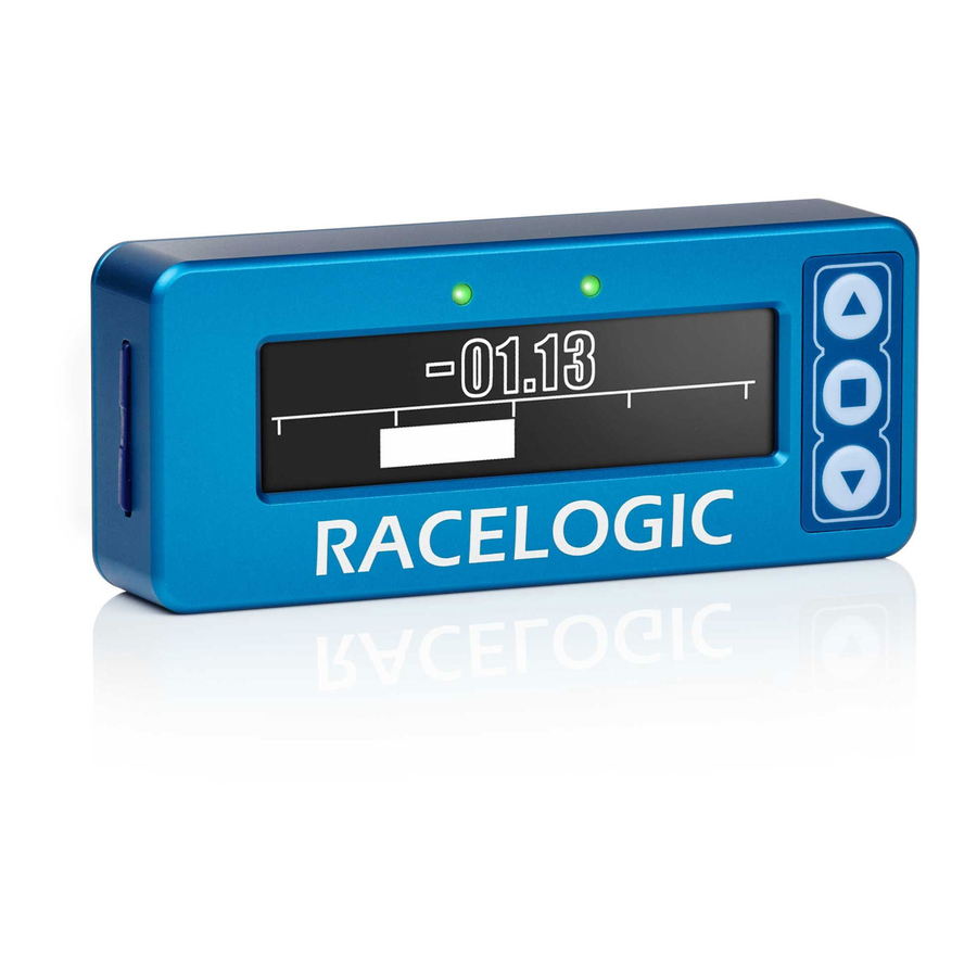
- Page 17 03 - VBOX II Display Screen Overview The screen will display data when the VB2 is operating. It also displays all the menus required to configure the VB2 via the front panel controls. On start-up, the display screen shows the unit’s firmware version and current offset value.
- Page 18 WAAS, SBAS or EGNOS Differential correction WAAS 40 cm Differential correction from Base station 40 cm Logged File name: When an SD card is inserted the file name of the logged file appears on the screen whilst data is being logged. https://en.racelogic.support//Product_Info/VBOX_Data_Loggers/VBOX_II_Range/VBOX_II_User_Guide/03_- _VBOX_II_Display_Screen_Overview...
- Page 19 Once physically connected and powered, open the software and use the drop down list to select the correct COM port that the VBOX II is connected to. VBOX Setup automatically connects to the selected device and enters the VBOX II setup screen.
-
Page 20: Software Overview
5. Write to unit - After making changes to setup, the write to unit button should be selected to ensure the settings have been uploaded. 6. Close - Closes the software, if changes have not been saved to the unit, you will be prompted to save the settings. https://en.racelogic.support//Product_Info/VBOX_Data_Loggers/VBOX_II_Range/VBOX_II_User_Guide/04_- _VBOX_II_VBOX_Setup_Overview... -
Page 21: General Menu
The side bar enables you to switch between the different settings menus; General, Channels, Logging, GPS, CAN and Output. Click on the menus below to view more information. General Menu Channels Menu Logging Menu CAN Menu GPS Menu Output Menu https://en.racelogic.support//Product_Info/VBOX_Data_Loggers/VBOX_II_Range/VBOX_II_User_Guide/04_- _VBOX_II_VBOX_Setup_Overview... - Page 22 Please also note that when using any GPS equipment, a clear sky view is important. Objects in the surrounding area such as tall buildings or trees can block the GPS signal causing a reduction in the number of satellites being tracked, or introducing reflected signals that can decrease the accuracy of the system. https://en.racelogic.support//Product_Info/VBOX_Data_Loggers/VBOX_II_Range/VBOX_II_User_Guide/05_- _VBOX_IISX_Single_Antenna_Placement...
- Page 23 However, if a test requires an antenna to be placed off of the vehicle, then a special Ground Plane ‘mushroom-style’ antenna must replace the off-vehicle antenna, as these antennas are capable of operating without a ground plane. The Ground Plane ‘mushroom’ style antennas RLVBACS065 are available from your VBOX distributor. RLVBACS065 'mushroom' type Ground Plane Antenna https://en.racelogic.support//Product_Info/VBOX_Data_Loggers/VBOX_II_Range/VBOX_II_User_Guide/05_- _VBOX_IISX_Single_Antenna_Placement...
- Page 24 If the separation is incorrect, data may not be given or may be inaccurate. The measured distance between the antennas should be the straight-line distance between the antennas regardless of the mounting angle. It is not the 2D distance between the antennas as viewed from above. https://en.racelogic.support//Product_Info/VBOX_Data_Loggers/VBOX_II_Range/VBOX_II_User_Guide/06_- _VBOX_20SL_Dual_Antenna_Placement...
- Page 25 Slip Angle Sensor has the ability to calculate any offset. See the Slip Angle Offset Section. However if you wish to measure Pitch or Roll then the alignment of the antennas must be in line with the vehicle or at as accurately as possible. https://en.racelogic.support//Product_Info/VBOX_Data_Loggers/VBOX_II_Range/VBOX_II_User_Guide/06_- _VBOX_20SL_Dual_Antenna_Placement...
- Page 26 The Ground Plane ‘mushroom’ style antennas RLVBACS065 are available from your VBOX distributor. If only one antenna will be placed ‘off-vehicle’ then only one Ground Plane antenna need be purchased. https://en.racelogic.support//Product_Info/VBOX_Data_Loggers/VBOX_II_Range/VBOX_II_User_Guide/06_- _VBOX_20SL_Dual_Antenna_Placement...
- Page 27 When the antenna separation is >2 m it is advised where possible to mount the antennas as level as possible so that the ‘LEVEL’ option can be enabled, otherwise the RTK lock is not so reliable and the Slip and Roll/Pitch data can drop out or https://en.racelogic.support//Product_Info/VBOX_Data_Loggers/VBOX_II_Range/VBOX_II_User_Guide/06_- _VBOX_20SL_Dual_Antenna_Placement...
-
Page 28: Gps Antenna
The VB20SL must only be used with the supplied antenna, unless instructed otherwise by Racelogic. GPS Antenna The GPS Antennas supplied with the VB20SL are 3.5 V active antennas. For the best possible signal quality, it is important to maintain a clean connection between the antennas and the VBOX. Before fixing the antennas to the VBOX, ensure that there are no dust particles in either connector. - Page 29 The measured distance between the antennas should be the straight-line distance between the antennas regardless of the mounting angle. It is not the 2D distance between the antennas as viewed from above. https://en.racelogic.support//Product_Info/VBOX_Data_Loggers/VBOX_II_Range/VBOX_II_User_Guide/07_- _VBOX_20SL3_Triple_Antenna_Placement...
- Page 30 When measuring Slip angle Antenna B can be placed either in front or behind Antenna A. If it is placed behind Antenna A as in the picture above then the ‘Swap Antenna’ option needs to be enabled in the Antenna configuration options. https://en.racelogic.support//Product_Info/VBOX_Data_Loggers/VBOX_II_Range/VBOX_II_User_Guide/07_- _VBOX_20SL3_Triple_Antenna_Placement...
- Page 31 If a vehicle roof also has obstacles such as roof bars then Ground plane antennas should be used as they can be mounted higher than the obstacle. The Ground Plane ‘mushroom’ style antennas RLVBACS065 are available from your VBOX distributor. If only one antenna will be placed ‘off-vehicle’ then only one Ground Plane antenna need be purchased. https://en.racelogic.support//Product_Info/VBOX_Data_Loggers/VBOX_II_Range/VBOX_II_User_Guide/07_- _VBOX_20SL3_Triple_Antenna_Placement...
- Page 32 When the antenna separation is >2M it is advised where possible to mount the antennas as level as possible so that the ‘LEVEL’ option can be enabled, otherwise the RTK lock is not so reliable and the Slip and Roll/Pitch data can drop out or https://en.racelogic.support//Product_Info/VBOX_Data_Loggers/VBOX_II_Range/VBOX_II_User_Guide/07_- _VBOX_20SL3_Triple_Antenna_Placement...
- Page 33 The VB20SL must only be used with the supplied antenna, unless instructed otherwise by Racelogic. GPS Antenna The GPS Antennas supplied with the VB20SL3 are 3.5v active antennas. For the best possible signal quality, it is important to maintain a clean connection between the antennas and the VBOX. Before fixing the antennas to the VBOX, ensure that there are no dust particles in either connector.
- Page 34 CAN bus or USB/serial connection bus along with all the other GPS data. NOTE: When measuring a braking distance the GPS optimisation must be set to High and the Kalman filter Velocity parameter set to 0 (zero), via the front panel controls or the VBOX Tools software. https://en.racelogic.support//Product_Info/VBOX_Data_Loggers/VBOX_II_Range/VBOX_II_User_Guide/07_- _VBOX_20SL3_Triple_Antenna_Placement...
- Page 35 If required, the Slip Angle offset can be re-calculated at any time by repeating this procedure. Selecting the ‘Clear Offset’ option in the Configuration Screen will clear the current offset value. https://en.racelogic.support//Product_Info/VBOX_Data_Loggers/VBOX_II_Range/VBOX_II_User_Guide/08_- _VBOX_20SL_Slip%2F%2FRoll_Angle_Offsets...
- Page 36 It is possible to request that the VB20SL3 calculates a Slip Angle Offset by sending it requests via CAN. The CAN Baud rate is 500Kbit/s, Motorola 11 bit – Standard Frame, The DLC = 8 The VB20SL3 will respond on CAN to indicate stages of the Slip offset process and also indicate completion or failure. https://en.racelogic.support//Product_Info/VBOX_Data_Loggers/VBOX_II_Range/VBOX_II_User_Guide/08_- _VBOX_20SL_Slip%2F%2FRoll_Angle_Offsets...
- Page 37 The Response message to indicate completion also contains the Offset value as a 32 bit IEEE float on Data bytes 2-5. In the example above Data bytes 2 - 5 = 3F 9D 70 A4 which equals a decimal value of 1.23 https://en.racelogic.support//Product_Info/VBOX_Data_Loggers/VBOX_II_Range/VBOX_II_User_Guide/08_- _VBOX_20SL_Slip%2F%2FRoll_Angle_Offsets...
- Page 38 If the expected angle between the antennas will be greater than 10 then the ‘LEVEL’ option should be disabled (set to ‘NO’). Note: When the antenna separation is <2 m the RTK lock is very resilient in most conditions and scenarios when the ‘Level’ option is not enabled. https://en.racelogic.support//Product_Info/VBOX_Data_Loggers/VBOX_II_Range/VBOX_II_User_Guide/08_- _VBOX_20SL_Slip%2F%2FRoll_Angle_Offsets...
- Page 39 09 - VBOX II CAN / RS232 / USB VBOX II units are equipped with a CAN bus interface, an RS232 serial socket and an USB socket. Either of the SERIAL or USB sockets can be used for all communication between the VBOX and a PC, including configuration of the VBOX and to transmit live data from the VBOX to the PC for viewing and performing real-time tests.
- Page 40 User defined channel properties Vehicle database channel properties Racelogic Modules Mode This mode should be selected when Racelogic modules are connected to the VBOX or VBOX CAN output is required. https://en.racelogic.support//Product_Info/VBOX_Data_Loggers/VBOX_II_Range/VBOX_II_User_Guide/09_- _VBOX_II_CAN_%2F%2F_RS232_%2F%2F_USB...
- Page 41 10 - VBOX II Smoothing and Filtering Velocity VBOX II units has three smoothing settings (Dynamic Modes) for velocity: High Dynamics, Normal and Low Dynamics. High dynamics has the least amount of smoothing and must be used for high dynamic tests where Time or Distance measurements are critical, such as brake stop and acceleration tests.
- Page 42 _VBOX_II_Smoothing_and_Filtering...
- Page 43 11 - VBOX II Digital and Analogue Outputs The outputs on connectors OUT1 and OUT2 can be used either as frequency/pulse digital outputs or as analogue outputs that can be configured to represent any of the following parameters: • Velocity •...
- Page 44 VB20SL3 VB20SL https://en.racelogic.support//Product_Info/VBOX_Data_Loggers/VBOX_II_Range/VBOX_II_User_Guide/11_- _VBOX_II_Digital_and_Analogue_Outputs...
- Page 45 VB2SX https://en.racelogic.support//Product_Info/VBOX_Data_Loggers/VBOX_II_Range/VBOX_II_User_Guide/11_- _VBOX_II_Digital_and_Analogue_Outputs...
- Page 46 12 - VBOX II Digital Inputs The DIGITAL I/O socket contains the two digital inputs for the VBOX II, accessed by connecting to different combinations of the three pins. The first digital input is most commonly referred to as the brake trigger input. This input is connected to an internal timer capture module that is able to record precisely an event time for use in brake distance calculation.
- Page 47 VB20SL VB2SX https://en.racelogic.support//Product_Info/VBOX_Data_Loggers/VBOX_II_Range/VBOX_II_User_Guide/12_- _VBOX_II_Digital_Inputs...
- Page 48 13 - VBOX II Inputs/Outputs VB20SL3 https://en.racelogic.support//Product_Info/VBOX_Data_Loggers/VBOX_II_Range/VBOX_II_User_Guide/13_- _VBOX_II_Inputs%2F%2FOutputs...
- Page 49 VB20SL VBSX10 https://en.racelogic.support//Product_Info/VBOX_Data_Loggers/VBOX_II_Range/VBOX_II_User_Guide/13_- _VBOX_II_Inputs%2F%2FOutputs...
- Page 50 14 - VBOX II Fuse Reset Button VBOX II units contain a fuse to protect it from excessive currents. If the unit is accidentally subjected to large currents and the fuse has become tripped, it can be reset by pressing the button marked ‘Fuse Reset’ all the way into the unit with a long, thin implement.
- Page 51 VBOX II Technical Specification How to update the VBOX II Firmware. VBOX II GPS, outputs/inputs and physical Occasionally Racelogic will release new versions specification information of firmware (internal code) for VBOX II products, often to introduce new features https://en.racelogic.support//Product_Info/VBOX_Data_Loggers/VBOX_II_Range/VBOX_II_User_Guide/15_- _VBOX_II_Technical_Properties1...
- Page 52 VBOX II CAN Output Note: Channels highlighted in Blue are only present on outputs from SL type units. Data format: Motorola Data Bytes 0x301 (1) Sats (2) Time since midnight UTC (3) Position – Latitude DDMM.MMMMM 0x302 (4) Position – Longitude DDMM.MMMMM (5) Velocity (kts) (6) Heading (º)
- Page 53 18. Slip Angle, 16-bit signed integer * 100. 19. Pitch Angle, 16-bit signed integer * 100. 20. Lateral Velocity, 16-bit signed integer * 100. 21. Yaw Rate, 16-bit signed integer * 100. 22. Roll Angle, 16-bit signed integer * 100 **VB20SL3 units only https://en.racelogic.support//Product_Info/VBOX_Data_Loggers/VBOX_II_Range/VBOX_II_User_Guide/15_- _VBOX_II_Technical_Properties/VBOX_II_CAN_Output...
- Page 54 VBOX II Dimensions VB2SX (all varients) and VB20SL https://en.racelogic.support//Product_Info/VBOX_Data_Loggers/VBOX_II_Range/VBOX_II_User_Guide/15_- _VBOX_II_Technical_Properties/VBOX_II_Dimensions...
- Page 55 VB20SL3 https://en.racelogic.support//Product_Info/VBOX_Data_Loggers/VBOX_II_Range/VBOX_II_User_Guide/15_- _VBOX_II_Technical_Properties/VBOX_II_Dimensions...
- Page 56 VBOX II PIN OUTS Connector 1 - POWER (Lemo 2 PIN) (Dedicated 4.5 – 36 V DC Power Connector) Function Power+ Ground Chassis Ground https://en.racelogic.support//Product_Info/VBOX_Data_Loggers/VBOX_II_Range/VBOX_II_User_Guide/15_- _VBOX_II_Technical_Properties/VBOX_II_PIN_OUTS...
- Page 57 Connector 2 / 3 - OUT 1 / OUT 2 (Lemo 3 PIN) (One Analogue and One Digital Output Each) Function Analogue Out 1 / 2 Digital Out 1 / 2 Ground Chassis Ground https://en.racelogic.support//Product_Info/VBOX_Data_Loggers/VBOX_II_Range/VBOX_II_User_Guide/15_- _VBOX_II_Technical_Properties/VBOX_II_PIN_OUTS...
- Page 58 Connector 4 - DIG I / O (Lemo 3 PIN) (Wheel Speed and Brake Trigger Inputs) Function Brake Trigger Chassis Ground https://en.racelogic.support//Product_Info/VBOX_Data_Loggers/VBOX_II_Range/VBOX_II_User_Guide/15_- _VBOX_II_Technical_Properties/VBOX_II_PIN_OUTS...
- Page 59 RS232 Tx GPS (Tx Data from GPS engine) RS232 Rx GPS (Rx Data to GPS engine) CAN High (direct connection between ports 5 and 6) CAN Low (direct connection between ports 5 and 6) Power + Chassis Ground https://en.racelogic.support//Product_Info/VBOX_Data_Loggers/VBOX_II_Range/VBOX_II_User_Guide/15_- _VBOX_II_Technical_Properties/VBOX_II_PIN_OUTS...
- Page 60 RS232 Tx GPS (Tx Data from GPS engine) RS232 Rx GPS (Rx Data to GPS engine) CAN High (direct connection between ports 5 and 6) CAN Low (direct connection between ports 5 and 6) Power + Chassis Ground https://en.racelogic.support//Product_Info/VBOX_Data_Loggers/VBOX_II_Range/VBOX_II_User_Guide/15_- _VBOX_II_Technical_Properties/VBOX_II_PIN_OUTS...
- Page 61 Connector 7 - USB (Setup / Upgrade) Function Power USB- USB+ Ground Chassis Ground https://en.racelogic.support//Product_Info/VBOX_Data_Loggers/VBOX_II_Range/VBOX_II_User_Guide/15_- _VBOX_II_Technical_Properties/VBOX_II_PIN_OUTS...
- Page 62 Connector 8 - GPS Antenna Function Signal Chassis Ground https://en.racelogic.support//Product_Info/VBOX_Data_Loggers/VBOX_II_Range/VBOX_II_User_Guide/15_- _VBOX_II_Technical_Properties/VBOX_II_PIN_OUTS...
- Page 63 VBOX II Standard Inventory Some items on the inventory differ between different VBOXII unit types. Items highlighted in BLUE are only delivered with SL type units, and items highlighted in YELLOW are only delivered with SX type units. Product Code...
- Page 64 Product Code Quantity Description RLACS106 VBOX Carry Case https://en.racelogic.support//Product_Info/VBOX_Data_Loggers/VBOX_II_Range/VBOX_II_User_Guide/15_- _VBOX_II_Technical_Properties/VBOX_II_Standard_Inventory...
- Page 65 VBOX II Technical Specification Velocity Accuracy 0.1 km/h (averaged over 4 samples) Units km/h or mph • 20 Hz - VB2SX, VB20SL, VB20SL3 • 10 Hz - VB2SX10 Update Rate • 5 Hz - VB2SX5 Maximum Velocity 1000 mph Minimum Velocity 0.1 km/h...
- Page 66 Brake stop accuracy • 20 Hz units: ±10 cm • 10 Hz unit: ±20 cm Accuracy • 5 Hz units: ±50 cm Memory SD Card Recording time Approx 4.3 MB/Hour @ 20 Hz Time Accuracy 0.01 s Resolution 0.01 s https://en.racelogic.support//Product_Info/VBOX_Data_Loggers/VBOX_II_Range/VBOX_II_User_Guide/15_- _VBOX_II_Technical_Properties/VBOX_II_Technical_Specification...
- Page 67 Accuracy w/ local upgrade 20 cm* • 1 cm (5 Hz / 10 Hz) Resolution • 1.85 mm (20 Hz) Height Accuracy 6 m* Height Accuracy w/ SBAS 2 m* Acceleration Accuracy 0.5 % Maximum 20 g Resolution 0.01 g https://en.racelogic.support//Product_Info/VBOX_Data_Loggers/VBOX_II_Range/VBOX_II_User_Guide/15_- _VBOX_II_Technical_Properties/VBOX_II_Technical_Specification...
- Page 68 <0.25° rms at 2 m antenna separation YAW rate YAW rate RMS Noise 0.75 degrees per second** Definitions * Circle of Error Probable (CEP): 95 % of the time the position readings will fall within a circle of the stated diameter https://en.racelogic.support//Product_Info/VBOX_Data_Loggers/VBOX_II_Range/VBOX_II_User_Guide/15_- _VBOX_II_Technical_Properties/VBOX_II_Technical_Specification...
- Page 69 –5 V to +5 V DC Velocity Default setting * 0.0125 Volts per km/h (0 to 400 km/h) Accuracy 0.1 km/h • 20 Hz - VB2SX, VB20SL, VB20SL3 • 10 Hz - VB2SX10 Update rate • 5 Hz - VB2SX5 https://en.racelogic.support//Product_Info/VBOX_Data_Loggers/VBOX_II_Range/VBOX_II_User_Guide/15_- _VBOX_II_Technical_Properties/VBOX_II_Technical_Specification...
- Page 70 VCI CAN mode Up to 16 channels from any external CAN module Up to 20 channels from any combination of ADC02, Racelogic modules mode ADC03, FIM02, TC8, Yaw sensor or CAN01 Digital Selectable signal polarity. 16 bit timer capture with 5 μs...
-
Page 71: How To Upgrade The Firmware
New firmware for VBOX II units can be loaded into the unit using a computer and the supplied USB cable. The latest firmware upgrade (.RUF) file for the VBOXII can be downloaded from the Owners Area of the...
Need help?
Do you have a question about the VBOX II and is the answer not in the manual?
Questions and answers