Table of Contents
Advertisement
Quick Links
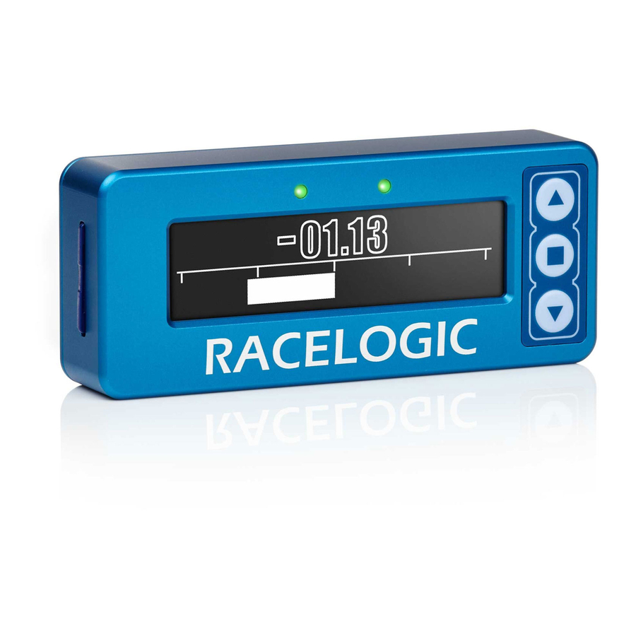
01 - VBOX II Front Panel
VBOX II units can be configured using the front panel buttons, which enables configuration without the need for a
computer. Configuration can also be made via the
VBOX Setup
Software.
From the main screen, press the'■' button to enter the configuration screen.
Note: Entering the configuration screen will cause the VBOX to stop logging to the SD card. When in
continuous logging mode, please ensure that the '■' button is pushed prior to removing the SD card to avoid
data loss.
Once in the configuration screen, press the '◄'and '►' buttons to highlight the next or previous choice in any menu, and
press '■' to select the highlighted option. Most Main menus contain sub-menus, for example the Settings and Setup
Antennas menus contain separate menus for each parameter.
Note: The options highlighted in blue are only available on the SL series units.
https://racelogic.support//01VBOX_data_loggers/VBOX_II_Range/VBOX_II_User_Guide/01_-_VBOX_II_Front_Panel
1
Advertisement
Table of Contents

Related Manuals for Racelogic VBOX II


Summary of Contents for Racelogic VBOX II
- Page 1 01 - VBOX II Front Panel VBOX II units can be configured using the front panel buttons, which enables configuration without the need for a computer. Configuration can also be made via the VBOX Setup Software. From the main screen, press the’■’ button to enter the configuration screen.
- Page 2 Long acc channels, and also Slip, Pitch, Roll, channels on SL units only. OUTPUTS Press ’■’ ’ configure the digital and analogue outputs. Press ’■’ to exit the setup menu and cause the settings EXIT to be saved in EEPROM https://racelogic.support//01VBOX_data_loggers/VBOX_II_Range/VBOX_II_User_Guide/01_-_VBOX_II_Front_Panel...
-
Page 3: Settings Menu
CAN MODE To connect any external CAN modules to the input of the VBOX II RACELOGIC MODULES MODE To connect Racelogic CAN modules to the RLVBOX II (input or output) Press ’■’ to enter the Log Options Menu. LOG OPTIONS In this menu the Logging Mode and Log rate can be set. - Page 4 BACK Press ’■’ to go back to the Main menu. https://racelogic.support//01VBOX_data_loggers/VBOX_II_Range/VBOX_II_User_Guide/01_-_VBOX_II_Front_Panel...
-
Page 5: Swap Antennas
Slip offset can be calculated and applied or cleared. Press ’■’ to enter the Pitch offset sub menu. Within this PITCH OFFSET sub menu a Pitch offset can be calculated and applied or cleared. BACK Press ’■’ to go back to the Main menu. https://racelogic.support//01VBOX_data_loggers/VBOX_II_Range/VBOX_II_User_Guide/01_-_VBOX_II_Front_Panel... -
Page 6: Roll Offset
But maximum ROLL or PITCH in this mode should be 10 degrees. Press ’■’ to enter the Roll offset sub menu. Within this ROLL OFFSET sub menu a Roll offset can be calculated and applied or cleared. BACK Press ’■’ to go back to the Main menu. https://racelogic.support//01VBOX_data_loggers/VBOX_II_Range/VBOX_II_User_Guide/01_-_VBOX_II_Front_Panel... - Page 7 Press ’■’ and then use the ‘◄’ and ‘►’ buttons to ROLL change the amount of smoothing applied to the Roll angle channel. Then press ’■’ to confirm. 0.0 – 5.0 (0.1 steps) BACK Press ’■’ to go back to the Main menu. https://racelogic.support//01VBOX_data_loggers/VBOX_II_Range/VBOX_II_User_Guide/01_-_VBOX_II_Front_Panel...
-
Page 8: Max Value
Only available when output is set to LAT ACC, LONG ACC, PITCH, SLIP or ROLL MAX FREQUENCY Press ’■’ and then use the ‘◄’ and ‘►’ buttons to set the maximum Frequency used on the digital output. Then press ’■’ to confirm. https://racelogic.support//01VBOX_data_loggers/VBOX_II_Range/VBOX_II_User_Guide/01_-_VBOX_II_Front_Panel... - Page 9 Press ’■’ and then use the ‘◄’ and ‘►’ buttons to set a TEST test value that the Digital output will simulate. Then press ’■’ to quit. Press ’■’ to exit the setup menu and cause the settings EXIT to be saved in EEPROM https://racelogic.support//01VBOX_data_loggers/VBOX_II_Range/VBOX_II_User_Guide/01_-_VBOX_II_Front_Panel...
- Page 10 -5 V. Then press ’■’ to confirm. -2 to 1 g (0.1g steps) LAT ACC VALUE @ -5V -2 to 1 g (0.1g steps) LONG ACC –180 to 179 (0.1 steps) for SLIP to 89 steps) for PITCH to 89 steps) for ROLL https://racelogic.support//01VBOX_data_loggers/VBOX_II_Range/VBOX_II_User_Guide/01_-_VBOX_II_Front_Panel...
- Page 11 Press ’■’ and then use the ‘◄’ and ‘►’ buttons to set a TEST test value that the Analogue output will simulate. Then press ’■’ to quit. Press ’■’to exit the setup menu and cause the settings EXIT to be saved in EEPROM. https://racelogic.support//01VBOX_data_loggers/VBOX_II_Range/VBOX_II_User_Guide/01_-_VBOX_II_Front_Panel...
-
Page 12: Dynamic Mode
To perform a factory reset on the unit, if for example the unit is not functioning correctly, press and hold the ’■’ and ‘►’ buttons whilst power is supplied to the VBOX II. The front panel screen will display an 'updating... - Page 13 https://racelogic.support//01VBOX_data_loggers/VBOX_II_Range/VBOX_II_User_Guide/01_-_VBOX_II_Front_Panel...
Need help?
Do you have a question about the VBOX II and is the answer not in the manual?
Questions and answers