Advertisement
Quick Links
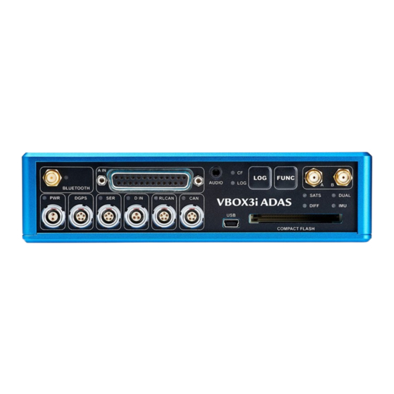
Installing VBOX 3i ADAS in the Vehicle
Best practise is to make sure that you have all the necessary equipment ready before you start installing systems on
vehicles.
Required Equipment to set up VBOX 3i ADAS
• VBOX unit
• Power cable
• USB cable
• Antenna(s)
• Antenna cable(s)
• Laptop
• VBOX Setup
Modules and accessories
This is a list of peripherals that you can use with VBOX 3i ADAS. Click on the product name to see the kit you need to
use it.
►IMU
• IMU unit
• IMU cable (RLCAB119)
►NTRIP modem
• NTRIP Modem
• Supplied NTRIP antenna
• SIM card/Mobile Phone
• NTRIP to VBOX Cable (RLCAB170)
• Laptop/mobile device for configuration
• Network information (if using SIM Card and internal modem)
https://en.racelogic.support//Product_Info/VBOX_Data_Loggers/VBOX_3i_Product_Range/VBOX_3i_ADAS/
User_Guide_VBOX_3i_ADAS/04_Installing_VBOX_3i_ADAS_in_the_Vehicle
1
Advertisement

Related Manuals for Racelogic VBOX 3i ADAS


Summary of Contents for Racelogic VBOX 3i ADAS
- Page 1 • Laptop • VBOX Setup Modules and accessories This is a list of peripherals that you can use with VBOX 3i ADAS. Click on the product name to see the kit you need to use it. ►IMU • IMU unit •...
- Page 2 • Radio Antenna (RLACS218) • Cable (RLCAB005) ►VBOX Manager • VBOX Manager Unit • Power cable (RLCAB005-C) ►Survey Pole • Survey Pole • Survey Antenna (RLACS320) • Survey antenna cable (RLCAB067) ►Survey Trolley • Survey Trolley kit ◦ TNC-to-SMA cable https://en.racelogic.support//Product_Info/VBOX_Data_Loggers/VBOX_3i_Product_Range/VBOX_3i_ADAS/ User_Guide_VBOX_3i_ADAS/04_Installing_VBOX_3i_ADAS_in_the_Vehicle...
- Page 3 Note: The primary antenna is Antenna A and the secondary antenna is Antenna B. 4. Connect the power cable to the PWR port on VBOX 3i ADAS. 5. Connect the Tablet/Laptop to the USB port on the VBOX 3i ADAS with the USB cable (RLCAB066-2). https://en.racelogic.support//Product_Info/VBOX_Data_Loggers/VBOX_3i_Product_Range/VBOX_3i_ADAS/...
- Page 4 Note: The Radio antenna must be at least 50 cm away from any other radio antenna. 3. Connect one end of an RLCAB005 cable to the port on the Radio unit. 4. Connect the other end of the cable to the DGPS port on VBOX 3i ADAS. https://en.racelogic.support//Product_Info/VBOX_Data_Loggers/VBOX_3i_Product_Range/VBOX_3i_ADAS/...
- Page 5 3. Connect the other end of the RLCAB170 cable to 3. Connect the other end of the RLCAB170 cable to the DGPS port on the VBOX 3i ADAS. the DGPS port on the VBOX 3i ADAS. This cable provides power to the modem from This cable provides power to the modem from the VBOX unit.
- Page 6 6. Check that the DIFF LED on the VBOX unit is message. solid green, indicating that it is receiving DGPS 6. Check that the DIFF LED on the VBOX unit is corrections. solid green, indicating that it is receiving DGPS corrections. https://en.racelogic.support//Product_Info/VBOX_Data_Loggers/VBOX_3i_Product_Range/VBOX_3i_ADAS/ User_Guide_VBOX_3i_ADAS/04_Installing_VBOX_3i_ADAS_in_the_Vehicle...
- Page 7 Inertial Measurements ►IMU Racelogic's Inertial Measurement Unit (RLVBIMU04) provides highly accurate measurements of pitch, roll, and yaw rate using three rate gyros, as well as x, y, z acceleration via three accelerometers. 1. Mount the IMU in the test vehicle (use the...
- Page 8 6. Drive in a figure of eight at least twice. The vehicle should be at a speed of more than 5 km/h during this procedure to generate sufficient force for the calibration process. Note: If you cannot do figure of eights, you can perform left/right slalom-type manouvres to achieve a similar effect. https://en.racelogic.support//Product_Info/VBOX_Data_Loggers/VBOX_3i_Product_Range/VBOX_3i_ADAS/ User_Guide_VBOX_3i_ADAS/04_Installing_VBOX_3i_ADAS_in_the_Vehicle...
- Page 9 • You change the VBOX IMU settings. • You use the VBOX Setup Software to read the VBOX unit's settings. • You use the VBOX Setup Software to read the External IMU settings. • You perform a GNSS Coldstart. https://en.racelogic.support//Product_Info/VBOX_Data_Loggers/VBOX_3i_Product_Range/VBOX_3i_ADAS/ User_Guide_VBOX_3i_ADAS/04_Installing_VBOX_3i_ADAS_in_the_Vehicle...
- Page 10 Note: The Radio antenna must be at least 50 cm away from any other radio antenna. 3. Connect one end of an RLCAB005 cable to the port on the Radio unit. 4. Connect the other end of the cable to the SER port on the VBOX 3i ADAS. https://en.racelogic.support//Product_Info/VBOX_Data_Loggers/VBOX_3i_Product_Range/VBOX_3i_ADAS/...
- Page 11 1. Connect one end of an RLVBCAB005-018 to the VB CAN port on the CAN Hub. 2. Connect the other end of the cable to the RL CAN port on the VBOX 3i ADAS. 3. Connect one end of a second RLVBCAB005-18 to the VB SER port.
- Page 12 Displays ►MFD Touch 1. Connect the RLCAB005-C cable to the bottom port on the right-hand side of the MFD Touch. 2. Connect the other end of the cable to the RL CAN port on the VBOX 3i ADAS. https://en.racelogic.support//Product_Info/VBOX_Data_Loggers/VBOX_3i_Product_Range/VBOX_3i_ADAS/ User_Guide_VBOX_3i_ADAS/04_Installing_VBOX_3i_ADAS_in_the_Vehicle...
- Page 13 1. Connect the RLCAB005-C cable to one of the two ports on the left-hand side of the VBOX Manager. You can use either connector for this functionality. 2. Connect the other end of the cable to the RL CAN port on the VBOX 3i ADAS. https://en.racelogic.support//Product_Info/VBOX_Data_Loggers/VBOX_3i_Product_Range/VBOX_3i_ADAS/...
- Page 14 2. Attach the survey antenna (RLACS320) to the threaded top of the pole. 3. Connect the antenna cable ( RLCAB067) to the port on the survey antenna. 4. Connect the other end of the antenna cable to the primary antenna port (A) on VBOX 3i ADAS. ►Survey Trolley Connect 1.
- Page 15 Note: The Radio antenna must be at least 50 cm away from any other radio antenna. 3. Connect one end of an RLCAB005 cable to the port on the Radio unit. 4. Connect the other end of the cable to the SER port on the VBOX 3i ADAS. https://en.racelogic.support//Product_Info/VBOX_Data_Loggers/VBOX_3i_Product_Range/VBOX_3i_ADAS/...
- Page 16 User_Guide_VBOX_3i_ADAS/04_Installing_VBOX_3i_ADAS_in_the_Vehicle...
- Page 17 Common system configurations - connection diagrams ▼VBOX 3i ADAS with NTRIP https://en.racelogic.support//Product_Info/VBOX_Data_Loggers/VBOX_3i_Product_Range/VBOX_3i_ADAS/ User_Guide_VBOX_3i_ADAS/04_Installing_VBOX_3i_ADAS_in_the_Vehicle...
- Page 18 ▼VBOX 3i ADAS with NTRIP and IMU https://en.racelogic.support//Product_Info/VBOX_Data_Loggers/VBOX_3i_Product_Range/VBOX_3i_ADAS/ User_Guide_VBOX_3i_ADAS/04_Installing_VBOX_3i_ADAS_in_the_Vehicle...
- Page 19 ▼VBOX 3i ADAS with Base Station https://en.racelogic.support//Product_Info/VBOX_Data_Loggers/VBOX_3i_Product_Range/VBOX_3i_ADAS/ User_Guide_VBOX_3i_ADAS/04_Installing_VBOX_3i_ADAS_in_the_Vehicle...
- Page 20 ▼VBOX 3i ADAS with Base Station and IMU https://en.racelogic.support//Product_Info/VBOX_Data_Loggers/VBOX_3i_Product_Range/VBOX_3i_ADAS/ User_Guide_VBOX_3i_ADAS/04_Installing_VBOX_3i_ADAS_in_the_Vehicle...
Need help?
Do you have a question about the VBOX 3i ADAS and is the answer not in the manual?
Questions and answers