
Related Manuals for SMA POWER REDUCER BOX


Summary of Contents for SMA POWER REDUCER BOX
- Page 1 Device for Power Control of PV Plants POWER REDUCER BOX User Manual REDUCERBOX-BA-en-16 | 98-0018716 | Version 1.6...
-
Page 3: Table Of Contents
Product Description ......14 Power Reducer Box........14 Type Label . - Page 4 Power Reducer Box........
- Page 5 Updating the Firmware via an SD Card ......56 10.7 Resetting the Power Reducer Box ..... . . 57 10.8 Information on the "prb.cfg"...
- Page 6 Technical Data ........72 13.1 Power Reducer Box........72 13.2 Plug-in Power Supply (CINCON, TRG30R 120) .
-
Page 7: Information On This Document
(see Section 2.3 "Qualification of Skilled Persons", page 11). These tasks are identified by an information note. Additional Information Links to additional information can be found at www.SMA-Solar.com. Document title Document type Reactive Power and Grid Integration... - Page 8 1 Information on this Document SMA Solar Technology AG Typography Typography Explanation Example "Light" • Display messages • The value can be read off in the "Energy" field. • Elements on a user interface • Select "Settings". • Connections • Enter the value 10 in the Minutes •...
-
Page 9: Safety
The network operator can use the Power Reducer Box to temporarily and remotely limit the feed-in capacity of the PV plant in the case of a grid overload. The Power Reducer Box translates the control commands of the network operator and transmits them to the Sunny WebBox. The Sunny WebBox forwards the control commands to the inverter. -
Page 10: Supported Products
• Sunny Portal • SMA Update-Portal * Requirements: the transmission protocol of your plant must be set to SMA-NET and the Sunny WebBoxes must not be operated in DHCP mode. ** The Sunny WebBoxes must not be operated in DHCP mode. -
Page 11: Qualification Of Skilled Persons
• Earth yourself before touching any components. Data Security You can connect the Power Reducer Box to the Internet. When accessing via the Internet, there is the risk that unauthorised users may access and manipulate the data or devices in your plant. -
Page 12: Operating Instructions
Inverters that are not supported do not implement the parameters via the Power Reducer Box. The setpoint of the network operator can however be achieved. For this the status configuration of the Power Reducer Box must be adjusted so that the output of the supported inverters is more strongly controlled. -
Page 13: Scope Of Delivery
SMA Solar Technology AG 3 Scope of Delivery Scope of Delivery Check the scope of delivery for completeness and any externally visible damage. Contact your specialist dealer if the delivery is incomplete or damaged. Figure 1: Components included in scope of delivery... -
Page 14: Product Description
Ethernet network to the registered Sunny WebBoxes. The Sunny WebBoxes contacted transfer the instruction to the connected inverters. Events are recorded in the internal memory of the Power Reducer Box. It is also possible to save events onto an SD card or to download events via the user interface. - Page 15 SMA Solar Technology AG 4 Product Description Figure 2: Principle of implementing grid management with the Power Reducer Box and the Sunny WebBox Figure 3: Principle of implementing grid management with the Power Reducer Box and the Sunny WebBox with Bluetooth User Manual REDUCERBOX-BA-en-16...
- Page 16 The diagram for the principle of implementing grid management does not replace the exact terminal assignment for connecting the Power Reducer Box to the local network. The exact terminal assignment can be found in Section 8.1.7 "Connecting the Power Reducer Box to the Local Network", page 36.
-
Page 17: Type Label
SMA Solar Technology AG 4 Product Description 4.2 Type Label The type label provides unique identification of the Power Reducer Box. The type label is located on the back of the Power Reducer Box. Figure 4: Information on the type label Item... -
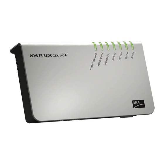
Page 18: Leds
Currentness of the data in Sunny Portal The Power Reducer Box sends data to the Sunny Portal as soon as events occur or settings are made via the user interface. The data in Sunny Portal can be displayed with a time delay, depending on your Internet connection and the processing of data in Sunny Portal. -
Page 19: System Requirements Of The Computer
SMA Solar Technology AG 4 Product Description 4.5 System Requirements of the Computer Supported Internet browsers: • Microsoft Internet Explorer from version 8 • Mozilla Firefox from version 3.6 • Google Chrome from version 23.0 • Apple Safari from version 5.1.7 •... -
Page 20: The Power Reducer Box User Interface
In order to prevent two users effecting contradictory settings at the same time, only one user can ever be logged on to the Power Reducer Box at one time. In addition to the rights of the "User" user group, the "Installer" user group has the following rights: •... -
Page 21: Overview Of The Login Page
SMA Solar Technology AG 5 The Power Reducer Box User Interface 5.2 Overview of the Login Page Figure 6: Login page of the Power Reducer Box on the computer Item Description Device status Language selection Login area Serial number and software version... -
Page 22: Overview Of The User Interface
5 The Power Reducer Box User Interface SMA Solar Technology AG 5.3 Overview of the User Interface You can operate the Power Reducer Box via the user interface. Figure 7: Layout of the user interface Item Description Main menu Context menu Content area 5.4 Main menu... -
Page 23: Context Menu
K1 to K4 relate to the respective connected relays. If no signal is incoming, the value "Open" is displayed. Display of the current status of the Power Reducer Box The device status is also displayed on the login page of the Power Reducer Box. User Manual REDUCERBOX-BA-en-16... -
Page 24: Events Page
5 The Power Reducer Box User Interface SMA Solar Technology AG In the lower area all Sunny WebBoxes registered in the Power Reducer Box are listed with their current communication status. A Sunny WebBox can have the following status: Symbol... -
Page 25: Mounting
☐ Lay the cables so that they cannot loosen due to their own weight. ☐ Do not cover the Power Reducer Box. This can lead to heat accumulation in the device. ☐ You can mount the Power Reducer Box together with the necessary network technology (e.g. -
Page 26: Mounting The Power Reducer Box On The Wall
6.3 Mounting the Power Reducer Box on a Top-Hat Rail 1. Hook both lower brackets of the Power Reducer Box under the lower edge of the top hat rail. 2. Push the Power Reducer box upwards and snap the top-hat rail into the upper brackets. -
Page 27: Connection
Overview of the connection area Item Description Connection for the plug-in power supply AUXCOM for connection to the ripple control receiver Ethernet connection SD card slot All other connections on the Power Reducer Box have no function. User Manual REDUCERBOX-BA-en-16... -
Page 28: Connecting The Power Reducer Box To The Ripple Control Receiver
Danger to life due to electric shock from faulty cable connections between the Power Reducer Box and the ripple control receiver In the event of faulty cable connections to the Power Reducer Box, mains voltage may be present in the Power Reducer Box enclosure. - Page 29 Relay contact 3 yellow Relay contact 4 * DIN 47100 without colour repetition 2. Plug the 7-pole plug into the AUXCOM terminal on the Power Reducer Box. ☑ The Power Reducer Box is connected to the ripple control receiver. User Manual REDUCERBOX-BA-en-16...
-
Page 30: Lengthening The Connection Cable
SMA Solar Technology AG 7.3 Lengthening the Connection Cable If the length of the prefabricated cable is not sufficient to connect the Power Reducer Box to the ripple control receiver, a longer cable can be connected to the supplied plug and used. -
Page 31: Commissioning
1 Connecting the Power Reducer Box to the Computer Section 8.1.2 2 Setting the computer to the Standard Network Settings of the Power Reducer Box Section 8.1.3 3 When using a proxy server: Setting up a Proxy Exception Rule in Internet Explorer Section 8.1.4 4 Setting the Power Reducer Box to Local Network Settings Section 8.1.5... -
Page 32: Setting The Computer To The Standard Network Settings Of The Power Reducer Box
In the worst case, the computer will no longer be able to communicate with the Power Reducer Box. In order to be able to make changes to the network settings, you will require the necessary user rights on the computer. If in doubt, contact your network administrator. - Page 33 1. Start the computer. 2. In Windows select "Start > Settings > Network Connections". 3. Double click on the LAN connection used to connect the Power Reducer Box to the computer. • If Windows displays several LAN connections, there are probably several network connections installed on the computer.
-
Page 34: Setting Up A Proxy Exception Rule In Internet Explorer
7. Confirm the entries with [OK] and close each further window with [OK]. ☑ The proxy exception rule has now been set up. 8. Call up the home page of the Power Reducer Box in the Internet Explorer address bar (http:\\192.168.0.200). - Page 35 Each IP address may only appear once in the local network. The IP address may never end in 0 or 255. • In the "IP address" field, enter the IP address under which the Power Reducer Box is to be accessed.
-
Page 36: Resetting The Computer To Previous Network Settings
DCHP servers can list all devices to which you have assigned an IP address. You can identify the Power Reducer Box in the DHCP server by its MAC address. You can find the MAC address of your Power Reducer Box on the type label. - Page 37 SMA Solar Technology AG 8 Commissioning The Power Reducer Box has an integrated network terminal. It can use this to connect to every Ethernet network. The terminal supports both Ethernet and fast Ethernet networks (10/100 Mbit/s). The speed is switched automatically depending on the connected network switch, router or computer.
-
Page 38: Sunny Webbox Registration In The Power Reducer Box
These settings may only be configured by skilled persons The settings in this section may only be configured by a skilled person (see Section 2.3 "Qualification of Skilled Persons", page 11). Only Sunny WebBoxes that are controlled by the Power Reducer Box must be registered in the Power Reducer Box. Requirements: ☐... -
Page 39: Editing/Removing A Sunny Webbox
If you edit the configuration of Sunny WebBoxes in your plant or remove Sunny WebBoxes from your plant while the Power Reducer Box is sending an instruction to the them, the signal from the Power Reducer Box may not be translated correctly. -
Page 40: Configuring Operating Modes
The four digital inputs of the Power Reducer Box (K1, K2, K3, K4) can accept up to 16 different input statuses. In consultation with the responsible network operator, each input status can be assigned a different operating mode. - Page 41 SMA Solar Technology AG 8 Commissioning Figure 11: "Status configuration" page User Manual REDUCERBOX-BA-en-16...
-
Page 42: Setting Active Power Limitation
4. Put a tick in the "active" column next to the status to be configured. ☑ The status is active. Upon saving, it will be evaluated by the Power Reducer Box. 5. In the "Operating mode" column, select the "Effective power control" value of the status to be configured. -
Page 43: Setting The Cos Phi Setpoint
4. Put a tick in the "active" column next to the status to be configured. ☑ The status is active and will be evaluated by the Power Reducer Box upon saving. 5. In the "Operating mode" column, select the "Cos phi setpoint" of the status to be configured. -
Page 44: Setting General System Statuses
Once the setpoint has been reached, the Power Reducer Box switches to the status "Time interval in case of constant setting". Example: if 60 seconds is entered, the Power Reducer Box would transmit a control command to the registered Sunny WebBoxes every 60 seconds with the changed setpoint value. -
Page 45: Configuring And Activating "Fallback
"fallback". In this way, yield losses can be avoided. As soon as a valid input status is present, the "fallback" is reset and the Power Reducer Box again sets the latest requirements of the distribution grid operator. - Page 46 2. Select "Status configuration" in the context menu. 3. In the "Time" field in the "fallback" area, enter the time interval after which the Power Reducer Box should switch to "fallback" in the event of an invalid input status. Enter a time interval of between 1 hour and 99 hours.
-
Page 47: Operation
0000 1111 1. In the browser, enter the IP address of your Power Reducer Box. Tip: if you do not know the IP address of the Power Reducer Box, you can find it in the file "prb.cfg" (see Section 10.8). -
Page 48: Accessing The Power Reducer Box Via Sunny Portal
SMA Solar Technology AG 9.2 Accessing the Power Reducer Box via Sunny Portal If the Power Reducer Box is integrated into a local area network with a router, you can also access the user interface of the Power Reducer Box via the Sunny Portal. -
Page 49: Downloading Events
If the SD card has reached its capacity, saving is stopped. Old data files are not overwritten on the SD card. If the "SD-CARD" LED on the Power Reducer Box is red, the SD card is full or write-protected. Compatibility of the SD cards In order to ensure the SD card functions properly, use SD cards available from SMA Solar Technology AG. - Page 50 Power Reducer Box. ☑ The events are saved in the internal memory and additionally to the SD card. You can carry out further settings on the protocol file in the system settings of the Power Reducer Box (see Section 10.5 "Setting Protocol Files", page 54).
-
Page 51: Settings
5. Using the "Communication monitoring" drop-down list, set how often the Power Reducer Box should report to the Sunny Portal. If the Power Reducer Box does not report to the Sunny Portal within the set time period, the Sunny Portal can inform you via e-mail. -
Page 52: Removing A Power Reducer Box Registered In Sunny Portal From A Plant
10.1.2 Removing a Power Reducer Box Registered in Sunny Portal from a Plant In the following cases, a Power Reducer Box registered in Sunny Portal must be removed from a plant: • You selected the wrong plant during registration of the Power Reducer Box (see Section 10.1.1). -
Page 53: Changing Your Password
SMA Solar Technology AG 10 Settings 10.2 Changing your Password Password security In order to increase security, note the following points when selecting a password: • Minimum eight characters • Mix upper-case and lower-case letters • Use numbers and special characters 1. -
Page 54: Setting The Date And Time
If an automatic time synchronisation with Sunny Portal should take place (logging in to Sunny Portal is not necessary for this), place a checkmark next to "Time synchronisation". Manually entering the date and time is then no longer necessary. Note that the Power Reducer Box must have an Internet connection. -
Page 55: Firmware Update For The Power Reducer Box
10 Settings 10.6 Firmware Update for the Power Reducer Box 10.6.1 Configuring an Automatic Firmware Update You can set the Power Reducer Box to automatically update its firmware if a new update is available in the SMA Update-Portal. Requirements: ☐ The Power Reducer Box must be integrated into the local network (see Section 8.1) and must be connected to the Internet via a router. -
Page 56: Updating The Firmware Via An Sd Card
The firmware update fails if you switch off the Power Reducer Box during the update procedure or remove the SD card too early. • Do not switch off the Power Reducer Box and do not remove the SD card whilst the LEDs of the Power Reducer show a red light chaser. -
Page 57: Resetting The Power Reducer Box
10.7 Resetting the Power Reducer Box The reset button is situated in a small hole on the rear side of the Power Reducer Box. Depending on how long you press the reset button, the Power Reducer Box performs the actions listed in the... -
Page 58: Decommissioning
11.1 Switching the Power Reducer Box Off Data on the SD card may be lost If you switch the Power Reducer Box off whilst data is being saved to the SD card, data from the SD card may be lost. • Do not switch the Power Reducer Box off if the "SD CARD" LED is flashing orange or green (see Section 4.3). -
Page 59: Disposing Of The Power Reducer Box
11 Decommissioning 11.4 Disposing of the Power Reducer Box Dispose of the Power Reducer Box at the end of its service life in accordance with the disposal regulations for electronic waste that apply at the installation site at that time. User Manual... -
Page 60: Troubleshooting
12 Troubleshooting SMA Solar Technology AG 12 Troubleshooting 12.1 Status Displays of the LEDs Status Meaning Measure POWER Green The input status is valid. None COMMAND The input status is invalid. Trained electrically skilled persons only: • Check connection to the ripple control receiver. - Page 61 Sunny WebBox, see the available. Sunny WebBox user manual. Flashing Network is impaired. The Ensure that the Power Reducer Box is Sunny WebBoxes and the correctly connected to the local Sunny Portal are not network (see Section 8.1.7).
-
Page 62: Explanation Of The Leds At The Ethernet Terminal
Reset the Power Reducer Box (see Section 10.7) POWER Green The Power Reducer Box is None supplied with voltage. The Power Reducer Box is not Check power supply. supplied with voltage. 12.2 Explanation of the LEDs at the Ethernet Terminal Item Status Function... -
Page 63: General Troubleshooting
The network settings of the computer do not correspond to the Power Reducer Box network settings. Corrective measures: • Set the computer to the network settings of the Power Reducer Box (see Section 8.1.3). The network settings of the router do not correspond to the Power Reducer Box network settings. - Page 64 There is a fault in the local network: • Ensure that the Power Reducer Box is correctly connected to the local network (see Section 8.1.7). • Check whether the network components, patch cables or plug connectors are defective or damaged.
-
Page 65: Error Messages In Connection With Sunny Portal
12.4.1 Error Messages in the Events Logbook The following error messages will be displayed on the user interface of the Power Reducer Box and saved. Certain error messages will be displayed in connection with an error type and an error code. - Page 66 Corrective measures: "Upload failed. Error:" • Set the Power Reducer Box to the network settings of the proxy server and/or the router (see Section 8.1.5 and/or the router manual). (305) The settings for the proxy server are not correct.
- Page 67 Sunny Portal is not error" connected to the local network. possible. Error:" Corrective measures: • Ensure that the Power Reducer Box is "Upload failed. Error:" correctly connected to the network (see Section 8.1.7) (405) Transfer method of the Power Reducer Box is not allowed on the Sunny Portal server.
- Page 68 "Sunny Portal (1312) The Sunny Portal may be overloaded or is is busy" currently down for maintenance. Corrective measures: • Wait until the Power Reducer Box automatically repeats the process at a later point in time. "Sunny Portal is − −...
-
Page 69: Errors During Registration In Sunny Portal
Corrective measures: • Repeat the process at a later time. "Device is already − The Power Reducer Box is already registered for a plant in registered in another Sunny Portal. plant." Corrective measures: • If desired, remove the Power Reducer Box from the plant in Sunny Portal (see Section 10.1.2) and... - Page 70 • If the Sunny Portal server is not available for more that 8 hours, contact the SMA Service Line. (405) Transfer method of the Power Reducer Box is not allowed on the Sunny Portal server. Corrective measures: • Contact the SMA Service Line.
- Page 71 Corrective measures: and/or password!" • Register at least one Sunny WebBox in Sunny Portal. Register the Power Reducer Box with the user name and password given in Sunny Portal (see 10.1.1). "No plants available in − There are still no plants registered for the given user in Sunny Portal."...
-
Page 72: Technical Data
13 Technical Data SMA Solar Technology AG 13 Technical Data 13.1 Power Reducer Box Mechanical Data Width x height x depth 255 mm x 130 mm x 57 mm Weight 750 g Degree of protection IP20 Ambient Conditions during Operation Ambient temperature −... - Page 73 Connection Cable for Ripple Control Receiver Prefabricated cable length 2.5 m Maximum permissible cable length 30 m Cable type LiYCY Power Reducer Box terminal 7-pole plug Ripple control receiver terminal 5 x 0.5 mm AUXCOM for Digital Inputs Maximum closing resistance 1 k Ω...
-
Page 74: Plug-In Power Supply (Cincon, Trg30R 120)
13 Technical Data SMA Solar Technology AG 13.2 Plug-in Power Supply (CINCON, TRG30R 120) Mechanical Data Width x height x depth 107.8 mm x 57.5 mm x 33.5 mm Weight 300 g Voltage Supply Voltage 100 V … 240 V AC, 50/60 Hz Nominal current 0.8 A... -
Page 75: Accessories
SMA Solar Technology AG 14 Accessories 14 Accessories Description Brief description SMA order number SD card Memory card with a memory SD-CARD2GB capacity of 2 GB User Manual REDUCERBOX-BA-en-16... -
Page 76: Contact
SMA Solar Technology AG 15 Contact If you have technical problems concerning our products, contact the SMA Service Line. We require the following information in order to provide you with the necessary assistance: • Information on the Ethernet network used •... - Page 79 Legal Provisions The information contained in this document is the property of SMA Solar Technology AG. Publishing its content, either partially or in full, requires the written permission of SMA Solar Technology AG. Any internal company copying of the document for the purposes of evaluating the product or its correct implementation is allowed and does not require permission.
Need help?
Do you have a question about the POWER REDUCER BOX and is the answer not in the manual?
Questions and answers