
Related Manuals for Extech Instruments MS400


Summary of Contents for Extech Instruments MS400
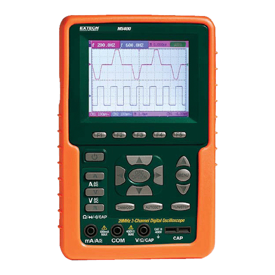
- Page 1 User Manual Handheld Digital Storage Oscilloscope & Multimeter Model MS400 Figure 1 – Meter Faceplate...
- Page 2 Warranty EXTECH INSTRUMENTS CORPORATION warrants this instrument to be free of defects in parts and workmanship for one year from date of shipment (a six month limited warranty applies to sensors and cables). If it should become necessary to return the instrument for service during or beyond the warranty period, contact the Customer Service Department at (781) 890-7440 ext.
-
Page 3: Table Of Contents
Multimeter Measurements Measuring Resistance Values Diode Measurement Continuity Tests Capacitance Measurement DC Voltage Measurement AC Voltage Measurement DC Current Measurement AC Current Measurement Freezing the Readings Taking a Relative Measurement Selecting Automatic/Manual Range Adjustment MS400 Version 2.0 – December 2007... - Page 4 Setting Time Base Mode Data Transmission – PC Interface Trouble Shooting Appendix Appendix and Specifications Oscilloscope Meter General Specifications Appendix B: Maintenance and Cleaning Common Maintenance Storage of Oscilloscope Replacing the Lithium Battery Unit MS400 Version 2.0 – December 2007...
-
Page 5: Safety Information
Extech as suitable for the Oscilloscope & Multimeter. ● Before use inspect voltage probes, test leads and accessories for mechanical damage and replace when required. ● Remove all probes, test leads and accessories that are not in use. MS400 Version 2.0 – December 2007... - Page 6 Make sure the product is operated in a well ventilated area. DO NOT operate this product in humid conditions. DO NOT operate this product where explosives are handled or used. Keep the product surface clean and dry. MS400 Version 2.0 – December 2007...
-
Page 7: General Inspection
General Inspection After purchasing a new MS400 oscilloscope, it is suggested that a general inspection of the instrument be performed according to the following steps: Check whether there is any damage to the product caused by shipping If the packing material, boxes or foam cushions are found in a damaged condition, keep them in a proper place until the complete instrument and accessories have passed electrical and mechanical tests. -
Page 8: Input Connections
The three circular jacks are used for voltage, current and resistance inputs, while the two square jacks are used for capacitance inputs 4. Oscilloscope probes 5. Oscilloscope channel inputs: The upper one is for Channel 1 (CH1) while the lower one is for Channel 2 (CH2) MS400 Version 2.0 – December 2007... - Page 9 7. V: Multimeter voltage measurement key 8. R: Multimeter resistance, diode, On/Off and capacitance measurement key 9. OSC LEFT: Oscilloscope left-direction adjustment key 10. OSC RIGHT: Oscilloscope right-direction adjustment key 11. OSC OPTION: Oscilloscope setting key MS400 Version 2.0 – December 2007...
- Page 10 16. RUN/STOP: key for starting or stopping an operation. 17. MENU DOWN: Move down the menu list. 18. MENU: Show / Hide the menu. 19. MENU UP: Move up the menu list. 20. F1~F5: Switch or Adjustment options for each menu MS400 Version 2.0 – December 2007...
-
Page 11: Using The Scope
The instrument then performs a self-check. A greeting window with “press any key to continue.” displays after the self-check. The user can press any key to enter the measurement functions. The oscilloscope powers up in the last setup configuration. Oscilloscope Operation Window Figure 4: Oscilloscope Operation Window MS400 Version 2.0 – December 2007... - Page 12 19. The red pointer gives the grounding data point for the waveform on CH1, which is the zero position of CH1. No display of this pointer indicates that the channel has not been opened. 20. Waveform display area. Red waveform represents CH1, blue waveform represents CH2. MS400 Version 2.0 – December 2007...
-
Page 13: Navigating A Menu
Function Menu. 2. Press the MENU UP or MENU DOWN key to select various function menus. 3. Choose a key from F1 to F5 to change the function setting. Figure 5: the Tool’s Menus MS400 Version 2.0 – December 2007... -
Page 14: Manually Setting The Vertical System, Horizontal System And Trigger Position
OSC LIFT or OSC RIGHT to adjust the horizontal time scale. 3. Press OSC OPTION once again, the following display is visible at bottom left side of the screen as shown in figure 7: LEFT/RIGHT – Time Base UP/DOWN – CH2 Volts/Div MS400 Version 2.0 – December 2007... - Page 15 Figure 8: Zero Point Position of Channel 1 Press OSC UP or OSC DOWN key to adjust the zero position of Channel 1 in the vertical direction and press OSC LIFT or OSC RIGHT key to adjust the horizontal position. MS400 Version 2.0 – December 2007...
- Page 16 Press the OSC UP or OSC DOWN key to adjust the trigger position of Channel 2 and press OSC LIFT or OSC RIGHT key to adjust the horizontal position. Press the OSC OPTION key again and return back to step 1. MS400 Version 2.0 – December 2007...
-
Page 17: Resetting The Oscilloscope
BNC jack inputs (CH1 and CH2) for scope measurements, three safety 4-mm banana jack inputs for Multimeter R, V and A measurements, and two square jack inputs for Multimeter capacitance measurements. Isolated inputs allow independent floating measurements between Multimeter and Scope. MS400 Version 2.0 – December 2007... -
Page 18: Displaying An Unknown Signal With Auto Set
3. Press the F4 key to select PK-PK CH2 from Peak-Peak item. The measurement 2 window turns blue in color and shows the peak-peak value for input CH2. Figure 12: Automatic Scope Measurements MS400 Version 2.0 – December 2007... -
Page 19: Freezing The Screen
3. Press the F3 key to select Average Factors, then, press F4 to jump to Averages. This averages the outcomes of 4, 16, 64, or 128 acquisitions and shows the final averaging result on the screen, shown as in the following figures. Figure 14: Average Factor Sampling Mode MS400 Version 2.0 – December 2007... -
Page 20: Using Persistence To Display Waveforms
2. Press the MENU UP or the MENU DOWN key to select the ACQU MODE. Four selectable items are displayed at the bottom of the screen. 3. Press the F2 key and jump to Peak Detect. Figure 16: Peak Detection MS400 Version 2.0 – December 2007... -
Page 21: Selecting Ac-Coupling
3. Press the F1 key and jump to AC. The bottom left side of the screen displays the ac- coupling icon. The user can view a screen that looks similar to the following Figure 17. Figure 17: AC-Coupling MS400 Version 2.0 – December 2007... -
Page 22: Reversing The Polarity Of The Displayed Waveform
2. Press the MENU UP or MENU DOWN key to select CH1 SETUP. Four selectable items are displayed at the bottom of the screen. 3. Press the F4 key to jump to Inverted. The inverted waveform of CH1 is displayed on the screen. Figure 18: Inverted MS400 Version 2.0 – December 2007... -
Page 23: Using Waveform Math Functions
Press the OSC OPTION key and the following will appear at the bottom left side of the screen. LEFT/RIGHT Time Base UP/DOWN CHM Vol Press the OSC UP or OSC DOWN key to adjust the displayed amplitude of the calculated waveform M. Figure 19: Waveform Mathematics MS400 Version 2.0 – December 2007... -
Page 24: Using The Multimeter
Auto refers to the measuring range in automatic operation mode. Measurement mode indicators: DCV: Direct voltage measurement ACV: Alternating voltage measurement DCA: Direct current measurement ACA: Alternating current measurement R: Resistance measurement : Diode measurement : Audible Continuity measurement C: Capacitance measurement MS400 Version 2.0 – December 2007... - Page 25 Absolute / Relative magnitude measuring control: The sign “||” expresses the absolute magnitude measuring control and “ ” represents the relative magnitude measuring control Manual measurement range control Test lead indicates the scale of a reading; different test modes use various colors MS400 Version 2.0 – December 2007...
-
Page 26: Multimeter Measurements
4. Connect the red and black test leads to the test points. If the resistance value of the tested point is less than 50Ω an audible beep will sound. Figure 23: Continuity. MS400 Version 2.0 – December 2007... -
Page 27: Capacitance Measurement
V/Ω banana jack input. 4. Connect the red and black test leads to the measurement points and the AC voltage value will be displayed on the screen. Figure 26: AC Voltage Measurement. MS400 Version 2.0 – December 2007... -
Page 28: Dc Current Measurement
4. Connect the red and black test leads to the measurement point and the AC current value will be displayed on the screen. Figure 29: AC Current Measurement MS400 Version 2.0 – December 2007... -
Page 29: Freezing The Readings
5. All subsequent readings will be displayed relative to the stored reference reading. Figure 32: Relative Measurement. MS400 Version 2.0 – December 2007... -
Page 30: Selecting Automatic/Manual Range Adjustment
To return to automatic mode, Press the F3 key and AUTO is displayed on the top left side of the screen. Figure 33: Automatic/Manual Range Adjustment MS400 Version 2.0 – December 2007... -
Page 31: Advanced Oscilloscope Functions
Select one setting according to the probe attenuation factor to ensure a correct vertical scale reading. Probe 100X 1000X Close Waveform is displayed normally. Invert Open Open the Invert function of the Waveform setting. MS400 Version 2.0 – December 2007... -
Page 32: Setting The Channel Coupling
Press F1 Coupling first and then press DC for a dc coupling setting. Both dc and ac components contained in the tested signal are permitted. The waveform is displayed as in Figures 35 and 36. Figure 35: AC Coupling Figure 36: DC Coupling MS400 Version 2.0 – December 2007... -
Page 33: Enabling The Scope Channels
Description CH1-CH2 CH1 waveform minus CH2 waveform. CH2-CH1 CH1 waveform minus CH2 waveform CH1+CH2 Add CH1 waveform to CH2 waveform CH1*CH2 Multiply CH1 waveform and CH2 waveform CH1/CH2 Divide CH1 waveform by CH2 waveform MS400 Version 2.0 – December 2007... -
Page 34: Setting The Trigger System
4. Press the OSC OPTION key and the following will be shown on the screen: LEFT/RIGHT – Time UP/DOWN – Trig 5. Press the OSC UP or OSC DOWN key to adjust the trigger level positions. MS400 Version 2.0 – December 2007... -
Page 35: Triggering Control
The HF part of the signal is prohibited and only the LF suppression component is allowed. The LF part of the signal is prohibited and only the HF suppression component is allowed to pass MS400 Version 2.0 – December 2007... -
Page 36: Video Triggering
Signal source Select CH1 as the trigger source. Select CH2 as the trigger source. SYNC Line Make a video line trigger synchronization setting Field Make a video field trigger synchronization setting. MS400 Version 2.0 – December 2007... -
Page 37: Acquire Mode' Setting
Displays the relative relationship between vertical voltage and horizontal time. Display CH1 on the horizontal axis and CH2 on the vertical axis. Communication Bitmap The data is transmitted as a bitmap Vector The data is transmitted as a vector MS400 Version 2.0 – December 2007... -
Page 38: Display Style
With the Persistence function selected, the displayed data gradually decays in color and the new data is shown bright in color. In the infinite persistence mode, the recorded points will be kept on the screen until the controlled value is changed. MS400 Version 2.0 – December 2007... -
Page 39: Xy Mode
Press the F4 key to select Start for address A. The Waveform saved in address A will be displayed on the screen in green and the zero point of Waveform k, voltage and time, will be purple MS400 Version 2.0 – December 2007... -
Page 40: Function Setting Menu
Measures the average value of CH2 Peak-to-Peak Measures the peak-to-peak value of CH1 value Measures the peak-to-peak value of CH2 RMS value Measures root mean square (RMS) value of CH1 Measures root mean square (RMS) value of CH2 MS400 Version 2.0 – December 2007... -
Page 41: Cursor Measurements
Displays the voltage cursor and menu Time Displays the time cursor and menu Signal CH1, CH2, ATH, Selects the Waveform channel on which the sources address A and cursor measurement will be performed address B. MS400 Version 2.0 – December 2007... - Page 42 Then adjust OSC UP or OSC DOWN so that the dashed line T2 is moving right and left while the time value of T1, relative to the screen middle point position, appears on the screen. Observe the absolute time values and frequencies for T1 and T2. MS400 Version 2.0 – December 2007...
-
Page 43: System State Menu
2. Press the MENU UP or MENU DOWN key to select SYS STAT. Four options appear at the bottom of the screen. 3. Sequentially press F1 through F4 and the corresponding status information will display. The following Figure 47 will be displayed. Figure 47: System State MS400 Version 2.0 – December 2007... -
Page 44: Setting Time Base Mode
6. Press F3, select window extension, the defined window extends to a full-screen display. Figure 48: Window Setting MS400 Version 2.0 – December 2007... -
Page 45: Data Transmission - Pc Interface
4. Use the supplied cable to connect the meter to the PC. 5. Open the supplied software program on the PC. 6. Set the parameters according to the Software User Guide or from the Help Utility available inside the software program to start data transmission. MS400 Version 2.0 – December 2007... -
Page 46: Troubleshooting
7. The display speed is unusually slow when attempting to select the average sampling in the sampling mode or while selecting a longer display time in the display mode for the oscilloscope This is normal. MS400 Version 2.0 – December 2007... -
Page 47: Appendix
Sampling rate and relay time ±100ppm(any time interval which is equal to or larger accuracy than 1ms) Time interval Single: ±(1 sampling interval ( T)measurement time+100ppm×reading+0.6ns) accuracy(full bandwidth) >average 16 : ±(1 sampling interval time +100ppm×reading+0.4ns) MS400 Version 2.0 – December 2007... - Page 48 Measurement: Cursor Voltage difference ( V) and time difference ( T) between cursors measurement Auto Peak-to-peak value, average value, root mean square value, measurement frequency and cycle. MS400 Version 2.0 – December 2007...
-
Page 49: Meter
40.00mA ±1%±1 digit 10uA 300.0mA ±1.5%±1 digit 100uA 20A (with adaptor) ±3%±3 digits 10mA Alternating Current (AC): Accuracy Resolution Range 40.00mA ±1.5%±3 digits 10uA 300.0mA ±2%±1 digit 100uA 20A (with adaptor) ±5%±3 digits 10mA MS400 Version 2.0 – December 2007... -
Page 50: General Specifications
10 to 30°C (50 to 86°F) 95 % 30 to 40°C (86 to 104°F) 75 % 40 to 50 °C (104 to 122°F) 45 % Temperature (storage) and Relative Humidity %: -20 to +60°C (-4 to +140°F) no condensation MS400 Version 2.0 – December 2007... -
Page 51: Appendix B: Maintenance And Cleaning
It is usually not required to replace the battery unit. But when it is required to be replaced only qualified personnel should carry out this operation and the battery should be replaced with the same specified lithium battery. MS400 Version 2.0 – December 2007...
Need help?
Do you have a question about the MS400 and is the answer not in the manual?
Questions and answers