
Subscribe to Our Youtube Channel
Related Manuals for Extech Instruments MG310


Summary of Contents for Extech Instruments MG310
- Page 1 USER MANUAL Insulation Resistance Tester With Continuity and AC Voltage modes Model MG310 ...
- Page 2 Always use the device as specified in the user manual, retain the manual for future use and check the www.extech.com website for newer versions of the user manual. Misuse of this device may cause personal injury and damage to the instrument and connected equipment. This symbol on the instrument indicates that for safe operation the user must use the instrument as described in the user manual. Danger icons: Alert to conditions and actions that may cause serious or fatal injury. Warning icons: Alert the user to the potential of electric shock. Caution icons: Alert to conditions and actions that may cause damage to the instrument or that may affect the instrument accuracy. Danger Do not measure circuits with voltages greater than 750V AC. Do not use this instrument in areas where flammable conditions exist. Do not use this instrument in areas of high humidity. Do not operate this instrument with wet hands. Do not touch conductive sections of the test leads when taking measurements. When test leads are shorted and connected to the instruments do not press the TEST button. Do not open the battery cover during tests. Do not touch the tested circuits or wires during insulation measurements. MG310-en-GB_V1.0 12/15...
- Page 3 Do not replace the batteries when the instrument is wet. Ensure secure connections with the test leads and the instrument’s test lead terminals. Shut the instrument down before opening the battery compartment. Caution Circuits under test must be completely discharged and isolated from power circuits before taking resistance measurements. If the test leads or adaptors need to be replaced due to damage, replace with test leads or adaptors of the same model or electrical specifications. Do not use the instrument if low battery indicator shows the low battery indicator. If the instrument will not be used for a long period, please remove the battery and store safely. Do not store or operate the instrument in areas of high temperature, high humidity, flame or explosive potentials, or where strong electromagnetic fields exist. Clean the instrument housing with a damp cloth and mild cleaning agent; do not use abrasives or solvents. If the instrument is wet, please dry before storing. Electrical Safety Symbols Risk of electrical shock Double insulation or reinforced insulation AC Measurement Ground MG310-en-GB_V1.0 12/15...
-
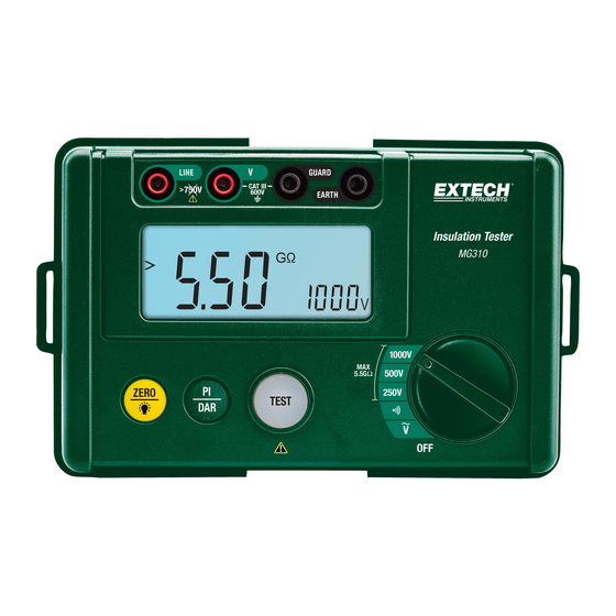
Page 4: Meter Description
6 7 8 1. EARTH terminal for Insulation Resistance and Continuity testing. 2. GUARD terminal for ACV and Continuity testing. 3. V terminal for ACV testing and Self‐Test mode. 4. LINE Terminal for Insulation Resistance testing and Self‐Test mode. 5. Backlit LCD Display 6. ZERO button (short press) and LCD Backlight ON/OFF button (long press) 7. PI/DAR Testing selection button 8. TEST button 9. Rotary function select switch Note: Secure battery compartment located on rear of unit. Control Buttons 1. PI/DAR button: Press to select PI polarization index and DAR dielectric absorption ratio test modes. 2. ZERO/Backlight button: Long press to enable/disable LCD backlight or short press to reset the display to zero for low resistance measurements. 3. TEST button: Engage/disengage testing for IR, Continuity, and AC Voltage tests. 4. Rotary function switch: Select an IR output test voltage (250V/500V/1000V), measure low resistance (Continuity), or measure AC Voltage (ACV). MG310-en-GB_V1.0 12/15... -
Page 5: Display Description
Display Description 3 4 5 Battery strength indicator DC/AC Voltage modes Voltage present alert PI test mode DAR test mode Time1 for PI/DAR tests Time2 for PI/DAR tests PI/DAR Test timer (minutes and seconds) Test voltage output [V] Units [G: Gigaohm; M: Megaohm] and Voltage [V] and Resistance [Ω] mode symbols Main measurement display ZERO function Under Range < Over Range > Audible continuity alert beeper Operating Instructions WARNING: Risk of electrocution. High‐voltage circuits, both AC and DC, are very dangerous and should be measured with great care. ALWAYS turn the function switch to the OFF position when the meter is not in use. If “OL” appears in the display during a measurement, the value exceeds the meter’s range. If the batteries are weak replace them before performing tests. The battery indicator on the upper left alerts the user when battery power is low. The battery compartment is accessed through the back of the meter secured by one Phillips head screw. DISPLAY BACKLIGHT Press and hold the backlight button for 2 seconds to switch the backlight on or off. For best battery efficiency use the backlight only when needed. HOLD The automatic hold function freezes the insulation resistance reading in the display for a short period of time for convenience. LOW BATTERY INDICATION When the icon appears in the display, the batteries should be replaced. Refer to the battery replacement section of this user manual. MG310-en-GB_V1.0 12/15... -
Page 6: Insulation Resistance Measurements
At the completion of a test, do not touch any parts of the circuit under test. Components may have become charged during the test and could discharge when touched. Select the desired test voltage using the rotary function switch. Select the 250V, 500V, or 1000V switch position for the corresponding output test voltage. Connect the red test lead to the meter’s LINE (4) jack and the black test lead to the EARTH (1) jack. Connect the probe end of the test leads to the circuit under test. Press the TEST button to test. The button will self‐lock and the button lamp will light. Note: If the circuit under test is live and has a voltage potential (AC/DC) over 30V, the meter will not test (the display will show the “>” icon and the symbol will flash; the buzzer will also sound). If the circuit under test is not live or if its voltage is less than 30V, the meter will begin applying high‐voltage to the circuit under test. The primary display will show the insulation resistance in MΩ (megaohms) or GΩ (gigaohms). The test voltage (VDC) value will be indicated in the right‐most auxiliary display, the symbol will flash and the caution buzzer will sound. Press to release the TEST button to stop the test. The high voltage will switch off and the resistance value indicated in the primary display will hold. Subsequently, the meter will internally discharge the balance of the insulation test voltage. Note: Turning the function switch to another test position will abort the test. A reading of >5.50 GΩ indicates that the meter reading is above the resistance threshold of that measurement range. MG310-en-GB_V1.0 12/15... - Page 7 POLARIZATION INDEX (PI) TESTING Read and understand all operations and safety information contained in the Insulation Resistance (IR) measurement section above and the Safety section before continuing. Connect the meter to the device under test as shown in the test section above. Select the desired output test voltage using the rotary function switch (250/500/1000V). Use the PI/DAR button to access the PI test mode. The display will show the PI icon when the PI mode is successfully accessed. The two test times (Time1 and Time2) will alternately show on the upper right. The first test will run for 1 minute (Time1) when the TEST button is pressed. If the test fails (no is displayed) the second test will not automatically run and testing is now complete. If the test passes (YES is displayed) the Time2 test will run for 10 minutes. The test result will display after the 10‐minute Time2 interval Press the TEST button to stop the test and to begin discharging the device under test. DIELECTRIC ABSORPTION RATIO (DAR) TESTING Read and understand all operations and safety information in the Insulation Resistance (IR) measurement section above and in the Safety section before continuing. Connect the meter to the device under test as shown in the IR test section above. Select the desired output test voltage using the rotary function switch (250/500/1000V). Use the PI/DAR button to access the DAR test mode. The display will show the DAR icon when the DAR mode is successfully accessed. The first two test times (Time1 and Time2) will alternately show on the upper right. The first test will run for 30 seconds (Time1) when the TEST button is pressed. If the test fails (no is displayed) the second test will not automatically run and testing is now complete. If the test passes (YES is displayed) the Time2 test will run for 1 minute. The test result will display after the 1‐minute Time2 interval To access the second set of Time1 and Time2 tests press the DAR button three times and repeat the same steps above in this section. For the 2 set of tests the times are 15 seconds (Time1) and 1 minute (Time2). When completed press the TEST button to stop the test and to begin discharging MG310-en-GB_V1.0 12/15...
- Page 8 LOW RESISTANCE CONTINUITY TESTING WARNING: To avoid electric shock, never measure continuity on circuits or wires that have voltage on them. Set the function switch to the (continuity) position. Insert the black test lead banana plug into the GUARD (2) jack. Insert the red test lead banana plug into the EARTH (1) jack. Press the TEST button. The button lamp will light indicating that testing can begin. Touch the test probe tips to the circuit or wire you wish to check. If the resistance is less than approximately 20Ω, the audible signal will sound and the audio icon will be displayed. If the circuit is open, the display will indicate > 220Ω. Press the TEST button again to disengage the test mode (the lamp will switch off) before removing the test leads from the circuit under test and from the meter. MG310-en-GB_V1.0 12/15...
-
Page 9: Ac Voltage Measurements
AC VOLTAGE MEASUREMENTS WARNING : Risk of Electrocution. The probe tips may not be long enough to contact the live parts inside some 240V outlets for appliances because the contacts are recessed deep in the outlets. As a result, the reading may show 0 volts when the outlet actually has voltage on it. Make sure the probe tips are touching the metal contacts inside the outlet before assuming that no voltage is present. CAUTION: Do not measure AC voltages if a motor on the circuit is being switched ON or OFF. Large voltage surges may occur that can damage the meter. Do not measure voltage higher than 750V AC. Please use extreme caution to avoid high voltage electrical shock while operating this instrument. Disconnect test leads from tested circuits and meter terminals after testing. Set the function switch to the V (ACV) position. Insert the black test lead banana plug into the GUARD jack (2). Insert red test lead banana plug into the V jack (3). Press the TEST button to engage the testing mode (the button lamp will light). Touch the black test probe tip to the one side of the circuit. Touch the red test probe tip to the other side of the circuit. Read the voltage in the main display. Press the TEST button again to disengage the test mode (the lamp will switch off) before removing the test leads from the circuit under test and from the meter. MG310-en-GB_V1.0 12/15... -
Page 10: Maintenance
2. USE AND STORE THE METER IN NORMAL TEMPERATURES. Temperature extremes can shorten the life of the electronic parts and distort or melt plastic parts. 3. HANDLE THE METER GENTLY AND CAREFULLY. Dropping it can damage the electronic parts or the case. 4. KEEP THE METER CLEAN. Wipe the case occasionally with a damp cloth. DO NOT use chemicals, cleaning solvents, or detergents. 5. USE ONLY FRESH BATTERIES OF THE RECOMMENDED SIZE AND TYPE. Remove old or weak batteries so they do not leak and damage the unit. 6. IF THE METER IS TO BE STORED FOR A LONG PERIOD OF TIME, the batteries should be removed to prevent damage to the unit. BATTERY INSTALLATION WARNING: To avoid electric shock, disconnect the test leads from any source of voltage before removing the battery cover. 1. Turn power off and disconnect the test leads from the meter. 2. Open the rear battery cover by removing the screw using a Phillips head screwdriver. 3. Insert the 6 x 1.5V ‘AA’ batteries into the battery holder, observing correct polarity. 4. Put the battery cover back in place. Secure with the screw. You, as the end user, are legally bound (EU Battery ordinance) to return all used batteries; disposal in the household garbage is prohibited! Dispose of used batteries / accumulators at collection points in your community or wherever batteries / accumulators are sold! Disposal: Follow the valid legal stipulations in respect of the disposal of the device at the end of its lifecycle WARNING: To avoid electric shock, do not operate the meter until the battery cover is in place and fastened securely. MG310-en-GB_V1.0 12/15... -
Page 11: Specifications
< 250K < 500K 1.00mA~1.10mA < 1M 1.00mA~1.10mA 1.00mA~1.10mA Short‐circuit Approx. 2mA Current Accuracy 0.00M~99.9M (3.0% + 5 digits) 100M~5.5G (5.0% + 5 digits) Polarization Index (PI) / Dielectric Absorption Ratio (DAR) PI measurement 1 minute : 10 minute insulation resistance test PI Value ≥ 4 4~2 2.0~1.0 ≤ 1.0 Criterion Best Good Warning Bad DAR measurement 30 second : 1 minute insulation resistance ratio test Set one DAR measurement 15 second : 1 minute insulation resistance ratio test Set two DAR value ≥ 1.4 1.25~1 ≤ 1.0 Criterion Best Good Bad MG310-en-GB_V1.0 12/15... - Page 12 Test button Red lamp on TEST button indicates that test is in progress. Self‐Test 10MΩ (±1%) Continuity Check Audible signal when resistance is < 20 (approx.). Battery Six (6) 1.5V ‘AA’ batteries Current Consumption 200mA approx. with maximum output (10mA under normal conditions). Operating Temperature 0ºC to 40ºC (32ºF to 104ºF) Storage Temperature ‐20 C to 60 C (‐4 F to 140 F) Operating Humidity < 85% RH Storage Humidity < 90% RH Operating Altitude 2000m (7000 ft.) maximum Weight 0.7kg. (1.5 lbs.) Size 150 x 100 x 71mm (6.0 x 4.0 x 2.8 in.) Safety This meter is intended for origin of installation use and protected by double insulation per EN61010‐1 and IEC61010‐1 2 Edition (2001) to Category III 600V; Pollution Degree 2. Copyright © 2015 FLIR Systems, Inc. All rights reserved including the right of reproduction in whole or in part in any form www.extech.com MG310-en-GB_V1.0 12/15...
Need help?
Do you have a question about the MG310 and is the answer not in the manual?
Questions and answers