
Related Manuals for Orbit OBR103


Summary of Contents for Orbit OBR103
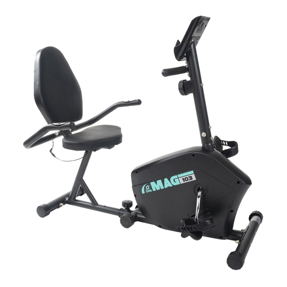
- Page 1 OBR103 OBR8301FC MAGNETIC BIKE OBR103 Mag Recumbent OWNER'S MANUAL BGR103 OBR8301FC Owner’s manual OBR103 OBR8301FC CONTENTS IMPORTANT INFORMATION ----- COMPLETE EXPLOSION DRAWING ----- PARTS LIST-----...
- Page 2 IMPORTANT INFORMATION SAFETY 1.Please keep this manual in a safe place for your reference when necessary. 2.Please do not assembly or use this equipment until you read this manual thoroughly & carefully. The safety and efficiency only can be achieved when the equipment is assembled ,maintained and used properly.
- Page 3 7.The equipment is designed for home use only, Maximum weight of the user is :100kg. 8.The equipment is not suitable for therapeutic use. 9.Wearing proper clothing while using the equipment, Avoid wearing loose clothing that may get caught in the equipment or that may restrict or prevent movements. 10.Keep your back straight while exercising.
- Page 4 MAINTENANCE 1. The safety level of the equipment only can be maintained if it is regularly examined for damage and or /wear and tear.(e.g. handle bar, pedals and seat ...etc.).It is vital that any faulty parts are replaced and the it is not used until completed repaired. 2.
- Page 5 Complete Explosion Drawing...
- Page 6 Part List NAME NAME Main Frame Washer D10 Rear Stabilizer Screw Front Stabilizer Magnet Board Rear Support Rack Tension Spring Saddle Axle of Rotation Backrest Circlip Front Post Screw Front Handle Bar Flywheel Axle Console Bearing seat end piece Adjusting Knob Bearing Pedal(L) Bearing end piece...
- Page 7 Assembling Instructions STEP 1 --Attach the rear stabilizer(2) to the rear support rack (4) with screws (66) ,waved washers (55) and cap nut(57)carefully. Note: The rear stabilizer(2) is without the transport wheel, don’t mix with the front stabilizer --Attach the front stabilizer(3) to the main frame(1) with screws (66) ,waved washers (55) and cap nut(57)...
- Page 8 STEP 2 Attach the backrest elbow tube(21) to the rear support rack(4) with screws(54), washers(56) and spring washers(58) correctly.
- Page 9 STEP 3 Attach the backrest (6) and saddle (5) to the backrest elbow tube (21) with screws(54) and washers (56) carefully and tightly.
- Page 10 STEP 4 --Attach the rear handle bar (28) to the backrest elbow tube (21) with screws(41) and waved washers (55) tightly. --Connect the pulse sensor wires(19&60) correctly.
- Page 11 STEP 5 --Connect the resistance adjuster wire (17&18) console wires (14&16) together carefully. Also connect the sensor wires (62&61) correctly. Please ensure that all the pins are straight when connecting 17& 18,14&16 and 62&61. Failure to do so will result in console malfunction.
- Page 12 STEP 6 --Attach the front handle bar(8) to the front post(7) with the screws (54) and waved washers(55) tightly. --Connect the wires(14&62) with the console(9) carefully. Then attach console (9) to the front post(7) with Note: 1. To sure a good connection when connecting the hand pulse sensors and main console wires firmly.
- Page 13 Caution: Now the equipment is completed assembled, if you find it not leveled on the floor, you can adjust it by the adjusting rear stabilizer tube plug(13). Make sure you have tightened all the screws and nuts well before beginning your workout.
- Page 14 CONSOLE INSTRUCTION SPECIFICATIONS : TIME ( TMR ) ……………………………………………………………….…00:00-99:59 SPEED(SPD) …………………………………………………………0.0-99.9KM/H(ML/H) DISTANCE(DIST) ………………………………………………………0.00-99.99KM(ML) CALORIES(CAL) ……………………………………………………………0.0-999.9KCAL ※ ODOMETER(ODO) ………………………………………………………0-9999KM(ML) ※ PULSE(PUL) ………………………………………………………………. …40-240BPM KEY FUNCTIONS: MODE: This key lets you to select and lock on to a particular function you want. ※...
- Page 15 pointer on the function you want which begins blinking. FUNCTIONS: 1. TIME: Press the MODE key until pointer lock on to TIME. The total working time will be shown when starting exercise. 2. SPEED: Press the MODE key until the pointer advance to SPEED. The current speed will be shown.
Need help?
Do you have a question about the OBR103 and is the answer not in the manual?
Questions and answers