Advertisement
Advertisement
Table of Contents

Related Manuals for AC Infinity AXIAL 8025


Summary of Contents for AC Infinity AXIAL 8025
- Page 1 AXIAL SERIES PROJECT COOLING FANS USER MANUAL USER MANUAL...
- Page 3 WELCOME Thank you for choosing AC Infinity. We are committed to product quality and friendly customer service. If you have any questions or suggestions, please don’t hesitate to contact us. Visit www.acinfinity.com and click contact for our contact information. EMAIL LOCATION support@acinfinity.com...
- Page 4 MANUAL CODE AF1802X1 PRODUCT MODEL UPC-A AXIAL 8025 HS8025A-X 854759004259 AXIAL 8038 LS8038A-X 854759004273 AXIAL 9225 HS9225A-X 854759004228 AXIAL 9238 HS9238A-X 854759004266 AXIAL 1225 LS1225A-X 854759004211 AXIAL 1238 HS1238A-X 854759004181 AXIAL 1751 HS1751A-X 854759004303 AXIAL S1225 AI-120SCX 854759004129 AXIAL S1225D...
-
Page 5: Table Of Contents
Page 6 Key Features ................. Page 7 Product Contents ................Page 8 Fan Replacement ................Page 9 Mounting ..................Page 12 Powering ..................Page 15 Speed Controller ................Page 16 Other AC Infinity Products ............. Page 17 Warranty ..................Page 18... -
Page 6: Fan Specifications
FAN SPECIFICATIONS CASE SIZE Square axial fans come in the standard sizes set by the industry. They are commonly quoted with millimeters in the format length time height times width. A case size measuring 120 mm tall, 120 mm long, and 38 mm wide may be quoted as 120 x 120 x 38 mm. CURRENT AND VOLTAGE Fans designed to be powered by alternating current are known as AC fans. -
Page 7: Key Features
KEY FEATURES ALUMINUM HOUSING THERMOPLASTIC PBT SPEED CONTROLLER* A heavy duty construction Materials used in the blade Allows control of the fans allows the fan to be used and impeller meet UL 94 speed and the ability to adjust in harsh environments and standards for resistance to the fans airflow and noise withstand shocks. -
Page 8: Product Contents
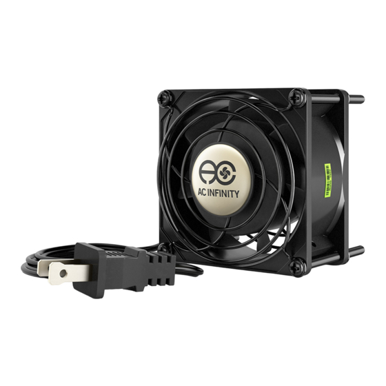
PRODUCT CONTENTS AXIAL 8025 AXIAL 9225 AXIAL 9225 HS8025A-X HS9225A-X LS1225A-X AXIAL 8038 AXIAL 9238 AXIAL 9238 LS8038A-X HS9238A-X HS1238A-X AXIAL LS1238 AXIAL 1751 LS1238A-X HS1751A-X AXIAL FAN (x1) FAN GUARDS (x2) SCREWS (x4) POWER CORD (x1) AXIAL S1225 AXIAL S1238... -
Page 9: Fan Replacement
FAN REPLACEMENT STEP 1- COMPATIBILITY Before you begin, please make sure that your new fan has a case size and voltage range that is compatible with the previous fan. Please turnoff any power going into your old fan. STEP 2 - PREVIOUS FAN HAS TERMINAL CONNECTORS If the fan you are trying to replace has terminal connectors, detach its power connector from the terminals by pulling it off the fan. - Page 10 FAN REPLACEMENT STEP 2 - PREVIOUS FAN HAS WIRED CONNECTORS If the fan you are trying to replace has permanent wires connected to the power source that can’t be removed by pulling on it, cut the wire to remove the previous fan. Then take the power plug cord included in this kit and remove the head with a wire stripper.
- Page 11 FAN REPLACEMENT STEP 4 - CONNECTING You can connect the two wire pairs by using a connect or block or electrical tape and wire connectors. Exposed wires and terminals can be hazardous when the fan is powered. STEP 5 - TERMINALS Mount the new fan into position using the previous fan’...
-
Page 12: Mounting
MOUNTING Please see page 14 for Hinge Mounting Instructions for Speed Control Fan Kits. STEP 1 - MARKING Use the fan to determine the exact position where you wish to mount it. Outline the center circle and four outer screw holes with a pencil. STEP 2 - DRILLING Attach a hole saw onto the power drill, create the center hole as outlined by your markings from the previous step. - Page 13 MOUNTING STEP 3 - POSITIONING Position the fan against the hole just created. Place a wire guard over the fan’s side and another guard on the opposite end while keeping the screw holes aligned. STEP 4 - MOUNTING Mount the unit using four machine screws while holding each corresponding nut in place.
- Page 14 MOUNTING Hinges are only included with Speed Control Fan Kits: S1225, S1225D, S1238, and S1238D. STEP 1 - ATTACHING HINGE To attach the hinge that is included in the kit, slide the screw through the front end of the fan and the hinge as shown.
-
Page 15: Powering
POWERING STEP 1 - TERMINAL After mounting your fan you can then attach the power plug cord onto the fans terminal. STEP 2 - POWERING Lastly, plug the cord’s head into a standard outlet. You may also power the fan with a wired power source, please see page 10 and 11. -
Page 16: Speed Controller
SPEED CONTROLLER LIGHT INDICATOR When the light is lit up then the speed controller is turned on and is receiving power. When the light is off then so is the controller and fan. To turn on the fan, turn clockwise until you feel a click and then keep turning until the fan is at full power. -
Page 17: Other Ac Infinity Products
AC INFINITY PRODUCTS AIRPLATE SERIES The AIRPLATE series is designed to cool home theater and audio video cabinets. The fans are powered by USB port or power outlets. Includes an inline speed controller and Boost Speed Adapter. The fans can also be temperature controlled with an Advance Thermal Controller (sold separately). -
Page 18: Warranty
This warranty program is our commitment to you, the original purchaser, that each product sold by AC Infinity will be free from defects in manufacturing for a period of two years from the date of purchase. If a product is found to have a defect in material or workmanship, we will take the appropriate actions defined in this warranty to resolve any issues. - Page 20 www.acinfinity.com...
Need help?
Do you have a question about the AXIAL 8025 and is the answer not in the manual?
Questions and answers