Table of Contents
Advertisement
Quick Links
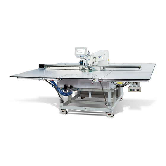
入力機能付き電子サイクルマシン ( ジーンズポケット付け仕様 )
Computer-controlled Cycle Machine (For sewing pockets on jeans) with an Input Function
带输入功能的电子循环缝缝纫机 ( 钉牛仔布口袋规格 )
AMS-221EN-HS3020/7200
取扱説明書 / パーツリスト
INSTRUCTION MANUAL / PARTS LIST
使用说明书 / 零件表
はじめに:
この取扱説明書 / パーツリストには AMS-221EN 標準仕様と異なる部分のみを記載してお
ります。記載されていない内容については「AMS-221EN/IP-420 取扱説明書およびパー
ツリスト」をご覧ください。
PREFACE :
This INSTRUCTION MANUAL/PARTS LIST describes only the parts which are different
from those of the standard AMS-221EN. Refer to the "AMS-221EN/IP-420 INSTRUCTION
MANUAL and PARTS LIST" for the parts which are not described.
前言 :
本使用说明书和零件表仅就有关与 AMS-221EN 标准规格不同的部分进行说明。关于没有说明的
内容,请参阅「AMS-221EN/IP-420 使用说明书和零件表」 。
No.02
40108398
Advertisement
Chapters
Table of Contents

Subscribe to Our Youtube Channel
Related Manuals for JUKI AMS-221EN-HS3020/7200


Summary of Contents for JUKI AMS-221EN-HS3020/7200
- Page 1 入力機能付き電子サイクルマシン ( ジーンズポケット付け仕様 ) Computer-controlled Cycle Machine (For sewing pockets on jeans) with an Input Function 带输入功能的电子循环缝缝纫机 ( 钉牛仔布口袋规格 ) AMS-221EN-HS3020/7200 取扱説明書 / パーツリスト INSTRUCTION MANUAL / PARTS LIST 使用说明书 / 零件表 はじめに: この取扱説明書 / パーツリストには AMS-221EN 標準仕様と異なる部分のみを記載してお ります。記載されていない内容については「AMS-221EN/IP-420 取扱説明書およびパー...
-
Page 4: Table Of Contents
目 次 1. 仕様 ............................1 2. 据え付け ..........................2 2-1. マーキングライトの取付け ........................2 2-2. アイガードの取付け ..........................2 3. パターンデータの作成方法 ....................3 3-1. 可縫エリアについて ..........................3 3-2. パターンデータ作成要領 ........................5 4. ポケットサイズの変更方法 ....................6 4-1. ユーザーパターン、VDT、M3、DAT 選択時 ...................6 4-2. パターンボタン登録時 ..........................7 5. ペダル操作方法A・Bの切替え ..................8 6. ペダル操作説明 ........................9 6-1. 標準動作 ..............................9 (1) 標準動作+ペダル操作A... - Page 5 1. 仕様 機種名 AMS-221EN-HS3020/7200 最高縫製速度 2,000 sti/min(ピッチ 3.5 mm以下のとき) X( 左右 ) 方向 Y( 前後 ) 方向 Sewing range × 246mm 200mm ※ ポケットサイズごとに、針と押え部品の接触を防止するための進入禁止エリ アが存在します。 縫い目長さ 0.1mm ~ 12.7mm (0.05mm 単位) 押え上昇量 押え枠先端基準で 46 ± 1mm 上糸調子 アクティブテンション ( 電子糸調子機構)...
-
Page 6: 据え付け
2. 据え付け 2-1. マーキングライトの取付け アーム上面の座ぐりタップ部に、カラー ❶ を挿入 し、マーキングライト取付板穴 ❷ とカラー ❶ をあ わせた状態で、止めねじ ❸ 2 本にて固定してくだ さい。 ❸ ❶ ❷ 2-2. アイガードの取付け 1) アイガードステー ❶ とアイガード連結板 ❷ を、結合ねじ ❸ で結合します。 ❷ ❸ ❶ 2) 面部カバー側面タップに連結板穴を合わせ、 アイガード取付ねじ ❹ で固定してください。 ❹ – 2 –... -
Page 7: パターンデータの作成方法
3. パターンデータの作成方法 3-1. 可縫エリアについて ポケットサイズの設定により、可縫エリアが異なります。パターンを作成する前に必ず確認してくだ さい。可縫エリアを間違えると、縫製エリアオーバー(E040)が発生します。 (ポケットサイズの設 定については、 「4. ポケットサイズの変更方法」p.6 をご参照ください。 ) Sサイズ・Y( 縦方向 ) : 1mm 〜 21mm 標準動作の可縫エリア ( Sサイズは、プラスチックブランクを 2 枚使用し、身頃押えとポケット押えを作成します。) Mサイズ Y(縦方向) :21 mm〜 96 mm 可縫エリア – 3 –... - Page 8 L サイズ Y(縦方向) :96 mm〜 117.9 mm 可縫エリア LL サイズ Y(縦方向) :117.9 mm〜 192.9 mm 可縫エリア – 4 –...
-
Page 9: パターンデータ作成要領
3-2. パターンデータ作成要領 パターン作成に必要な条件: 縫い形状・コバ幅・縫い目長さ・閂止の有無(有る場合はサイズと針数) 下図の様に入力してください。 ① 第 2 原点 ..原点から、X =- 120、Y=+100 まで空送り、第 2 原点とします。 ② 空送り ..第 2 原点から縫い始めまで空送り。 ③ 外周縫い ..外周縫いパターンを入力。 ④ 糸切り ..糸切りを入力。 ⑤ 外部出力 ..(ポケット押え退避信号)外部出力 0 を入力。 ⑥ 空送り ..外周縫いから内周縫いまで空送り。 (閂止め、縫い) ⑦ 内周縫い ..内周縫いパターンを入力。 ⑧ 糸切り ..糸切りを入力。 ⑥... -
Page 10: ポケットサイズの変更方法
4. ポケットサイズの変更方法 4-1. ユーザーパターン、VDT、M3、DAT 選択時 上記パターンデータ選択時、ポケットサイズを変更する場合は、メモリスイッチ U081 の設定値を選 択してください。 < 単独縫いデータ入力画面 > ピクト ポケットサイズ U081 設定値 標準動作 Sサイズ Mサイズ 82( 初期値 ) Lサイズ LLサイズ < 単独縫い縫製画面 > – 6 –... -
Page 11: パターンボタン登録時
4-2. パターンボタン登録時 パターンボタンに登録されたパターンは、メモリスイッチ U081 から変更する事なく、各 No. ごとに ポケットのサイズの変更を行うことができます。( パターンボタン選択時はメモリスイッチ U081 で 設定されたポケットサイズは無効となります。 ) ※ パターンボタンの登録方法についてはAMS -221EN 取扱説明書「Ⅱ -2-15. パターンボタンの 新規登録を行うには」p.46、 「Ⅱ -2-16. パターンボタン選択時の液晶表示部」p.47、 「Ⅱ -2-17. パターンボタン No. 選択を行うには」p.51、 「Ⅱ -2-18. パターンボタンの内容を変更するには」 p.53、 「Ⅱ -2-19. パターンボタンをコピーするには」p.54 を参照願います。 以下はAMS -221EN 取扱説明書「Ⅱ -2-18. パターンボタンの内容を変更するには」p.53 の内容と あわせて参照ください。... -
Page 12: ペダル操作方法A・Bの切替え
5. ペダル操作方法A・Bの切替え メモリスイッチ U239A ペダル操作 A・B 切替えより、ペダルの 動作を切り替えることができます。 押すと、反転し選択状態になります。 :ペダル操作 A :ペダル操作 B ペダル操作A・Bの基本的な動作は以下の通りです。 ペダルスイッチ C ペダルスイッチ A ペダルスイッチ B ペダル操作A ペダルスイッチ ............身頃押えの上昇・下降を行います。 ペダルスイッチ (軽く踏込んだ場合) ....ポケット押えの前進・後退を行います。 ペダルスイッチ (奥まで踏込んだ場合 ) ..ポケット押えの上昇・下降を行います。 ペダルスイッチ ........... 縫製開始 ペダル操作B ペダルスイッチ ..........1つ前の動作 (ポケット押えの上昇 ・ 後退、 身頃押えの上昇) を行います。 ペダルスイッチ... -
Page 13: ペダル操作説明
6. ペダル操作説明 メモリスイッチ U081 やパターンボタンにより設定されたポケットサイズ標準・S・M・L・LLと 操作 A・B 組み合わせによるミシン起動までの操作について説明します。 ※ 説明ではペダルと押えを以下のように表します。 身頃押え ポケット押え ペダルスイッチ B ペダルスイッチ C ペダルスイッチ A 6-1. 標準動作 (1) 標準動作+ペダル操作A (U081 : 80 U239 : A) 下降 1) 縫製物をセットし、ペダルスイッチ B を 下降 踏むと身頃押え・ポケット押えが下降し ます。 上昇 上昇 再度ペダルスイッチ B を踏み込むと身頃 押え、ポケット押えが上昇します。... -
Page 14: 標準動作+ペダル操作B (U081 : 80 U239 : B)
(2) 標準動作+ペダル操作B (U081 : 80 U239 : B) 下降 1) 縫製物をセットし、ペダルスイッチ B を 下降 踏むと身頃押え・ポケット押えが下降し ます。 上昇 上昇 2) 身頃押え・ポケット押えが共に下降状態 のときペダルスイッチ A を踏むと、身頃 押え・ポケット押えが上昇します。 3) 身頃押え、ポケット押えが共に下降状態 下降 下降 のときペダルスイッチ C を押すと縫製を 開始します。 – 10 –... -
Page 15: ポケットSサイズ設定
6-2. ポケットSサイズ設定 (1) ポケットSサイズ設定+ペダル操作A (U081 : 81 U239 : A) 上昇 1) 身頃をセットし、ペダルスイッチ A を踏 むと身頃押えが下降します。 下降 再度ペダルスイッチ A を踏み込むと身頃 押えが上昇します。 上昇 2) ポケットをセットし、身頃押えが下降し 下降 ている状態でペダルスイッチ B を踏むと ポケット押えが下降します。再度ペダル スイッチ B を踏むとポケット押えが上昇 します。 下降 下降 3) 身頃押え、ポケット押えが共に下降状態 のときペダルスイッチ C を押すと縫製を 開始します。... -
Page 16: ポケットM・L・Llサイズ設定
6-3. ポケットM・L・LLサイズ設定 (1) ポケットM・L・LLサイズ設定+ペダル操作A (U081 : 82・83・ 84 U239 : A) ※ M、L、LLサイズではポケット押えの前進量のみ異なります。ペダル操作は同一です。 1) 身頃をセットし、ペダルスイッチ A を踏 上昇 むと身頃押えが下降します。 再度ペダルスイッチ A を踏み込むと身頃 下降 押えが上昇します。 上昇 2) ポケットをセットし、身頃押え下降状態 でペダルスイッチ B を軽く踏むとポケッ ト押えが前進します。 後退 下降 ポケット押えが前進・上昇している状態 前進 でペダルスイッチ B から足を離すとポ ケット押えが後退します。 3) ポケット押えが前進している状態で、ペ 上昇... -
Page 17: ポケットM・L・Llサイズ設定+ペダル操作 B(U081 : 82・83・ 84 U239 : B)
(2) ポケットM・L・LLサイズ設定+ペダル操作 B(U081 : 82・83・ 84 U239 : B) ※ M、L、LLサイズではポケット押えの前進量のみ異なります。ペダル操作は同一です。 下降 1) 身頃をセットし、ペダルスイッチ B を踏 むと身頃押えが下降します。 2) ポケットをセットし、身頃押え下降状態 でペダルスイッチ B を踏むとポケット押 えが前進します。 前進 下降 3) ポケット押えが前進している状態でペダ ルスイッチ B を再度踏むと、ポケット押 えが下降します。 上昇 4) 身頃押え下降、ポケット押え前進・下降 の状態でペダルスイッチ A を踏むと、ポ ケット押えが上昇します。 5) 身頃押え下降、ポケット押え前進・上昇 の状態でペダルスイッチ... -
Page 18: ポケットの型の作成要領
7. ポケットの型の作成要領 7-1. ポケット型作成の基本 ポケット型作成の基本は、下記の通りです。 ポケットの形状に合わせる。 外側縫いの時に、中押えが干渉しない寸法に 合わせる。 (外側縫いより 3 mm以上内側) ( 注意 ) Sサイズの場合は、内側縫いの時に 中押えが干渉しない寸法に合わせる。 (外側縫いより 3 mm以上内側) 針 中押え すき間あり ポケット ポケット押え 身頃押え 3mm 以上 身生地 7-2. ポケットを指で押さえる場合 ポケットを指で押さえた状態で、ポケット押えを下 降させる場合は、指を入れる所を切り欠きます。 7-3. 内側縫いの時、ポケット押えに針或いは中押えが接触する場合 内側縫いの時、ポケット押えに針、あるいは中押 えが干渉する場合は、干渉する所を削ります。 – 14 –... -
Page 19: プラスチックブランク
8. プラスチックブランク ポケットの形状に合せて、プラスチックブランクからポケット押えを作成します。 プラスチックブランク ( 品番:40063821) 厚さ:3mm ( 注意 ) Sサイズは、プラスチックブランクを 2 枚使用し、身頃押えとポケット押えを作成します。 9. メモリスイッチ設定 メモリスイッチは出荷時に下記の設定値に設定されています。 (AMS-221ENHS3020 の初期値と異なる項目のみ掲載します。 ) 内容 初期値 備考 最高回転数 2000 縫い始め速度 2 2000 縫い始め速度 3 2000 縫い始め速度 4 2000 縫い始め速度 5 2000 原点復帰操作時の原点復帰選択 :パターンデータを逆トレース 外押え制御・ペダル開閉 ポケットサイズ... -
Page 20: エラーコード
10. エラーコード エラーコード ピクト エラー内容 表示メッセージ 復帰方法 復帰場所 E399 シ リ ン ダ ー 退 避 位 エアー OFF される 前画面 置エラー の で、 手 動 に て 退 避位置へ戻す。 11. オプション 部品名 種類 品番 備考 SS46 スタッカー装置 40114887 12. ポケット押え位置調整方法 ❶... - Page 21 13. グリースの塗布箇所 図 A ② 補足 ③ ① ② 【→:グリースの塗布箇所】 図 B 補足 ❶ 【軸 ( 図 A ① ) 部へのグリース塗布について】 ・ ねじ A をゆるめ、軸 ( 図 A ① ) を B 方向 にずらします。 ・ 筆などを使い、摺動部にグリースを塗布し ます。 ・ 軸 ( 図 A ① ) を戻し、 スラスト受け ( 図 A ② ) でスラストをとります。...
- Page 24 CONTENTS 1. SPECIFICATIONS ....................... 1 2. INSTALLATION ......................2 2-1. Installing the marking light ......................2 2-2. Installing the eye guard ........................ 2 3. HOW TO CREATE PATTERN DATA ................3 3-1. Possible sewing area ........................3 3-2. Pattern data creation instructions ....................5 4.
-
Page 25: Specifications
1. SPECIFICATIONS Model name AMS-221EN-HS3020/7200 Max. sewing speed 2,000 sti/min (when the stitch pitch is 3.5 mm or less) X (lateral) direction Y (longitudinal) direction Sewing range 246 mm × 200 mm * Entry prohibition area exists for each pocket size in order to prevent contact between the needle and the feeding frame components. -
Page 26: Installation
2. INSTALLATION 2-1. Installing the marking light Insert collars ❶ into the counter-bore tap section on the top of the machine arm. Fix the marking light with two setscrews ❸ with marking-light ❸ mounting plate holes ❷ aligned with collars ❶ . ❶... -
Page 27: How To Create Pattern Data
3. HOW TO CREATE PATTERN DATA 3-1. Possible sewing area The possible sewing area differs with the pocket size setting. Be sure to confirm the possible sewing area before creating a pattern. If the sewing area is not correct, "sewing area overrun" (E040) will occur. (Refer to "4. - Page 28 L size, Y (longitudinal direction): 96 mm to 117.9 mm [Possible sewing area] 2nd origin Entry prohibition area when the pocket clamp is retracted Possible sewing area Smallest possible sewing area when the pocket Entry prohibition area clamp is retracted when the pocket clamp is advanced Origin...
-
Page 29: Pattern Data Creation Instructions
3-2. Pattern data creation instructions Conditions necessary for the creation of a pattern: Sewing shape, edge width, stitch length, with/without bartacking (in the case of "with bartack- ing", its size and the number of stitches) Enter data as illustrated in the figure shown below: ①... -
Page 30: How To Change The Pocket Size
4. HOW TO CHANGE THE POCKET SIZE 4-1. When the user pattern, VDT, M3 or DAT is select In the case one of the aforementioned patterns is selected, the pocket size can be changed by selecting a desired setting of memory switch U081. <Independent sewing data entry screen>... -
Page 31: When Registering The Pattern Button
4-2. When registering the pattern button For a pattern registered to the pattern button, the pocket size can be changed on the basis of the pat- tern number without changing the pocket size with the memory switch U081. (When the pattern button is selected, the pocket size set by means of the memory switch U081 is disabled.) * Refer to the Instruction Manual for AMS-221EN "... -
Page 32: Changing Over The Method Of Pedal Operation Between A And B
5. CHANGING OVER THE METHOD OF PEDAL OPERATION BETWEEN A AND B Pedal operation can be changed over by changing over the memory switch U239 A pedal operation between A and B. When the button is pressed, the button is displayed in reverse video. -
Page 33: Explanation Of The Pedal Operation
6. EXPLANATION OF THE PEDAL OPERATION This section describes the operation to be carried out up to the start of the sewing machine by com- bining the pocket sizes; standard, S, M, L and LL, set by means of the memory switch U081 and the pattern button and the pedal operations A and B. -
Page 34: Standard Operation + Pedal Operation B (U081 : 80, U239 : B)
(2) Standard operation + Pedal operation B (U081 : 80, U239 : B) Lowered Lowered 1) When the sewing product is placed on the machine and the pedal switch B is de- pressed, the garment body clamp and the pocket clamp come down. Lifted Lifted 2) When the pedal switch A is depressed... -
Page 35: Setting The Pocket Size S
6-2. Setting the pocket size S (1) S size pocket setting + Pedal operation A (U081 : 81, U239 : A) Lifted 1) When the garment body is placed on the sewing machine and the pedal switch A is Lowered depressed, the garment body clamp comes down. -
Page 36: Setting The Pocket Sizes M, L And Ll
6-3. Setting the pocket sizes M, L and LL (1) M, L and LL sizes pocket setting + Pedal operation A (U081 : 82 • 83 • 84, U239 : A) * For the M, L and LL pocket sizes, only the amount of forward travel of the pocket clamp is different respectively. -
Page 37: M, L And Ll Sizes Pocket Setting + Pedal Operation B (U081 : 82 • 83 • 84, U239 : B)
(2) M, L and LL sizes pocket setting + Pedal operation B (U081 : 82 • 83 • 84, U239 : B) * For the M, L and LL pocket sizes, only the amount of forward travel of the pocket clamp is different respectively. -
Page 38: Pocket Clamp Preparation Instructions
7. POCKET CLAMP PREPARATION INSTRUCTIONS 7-1. Basics of the pocket clamp preparation Basic of the pocket clamp preparation is as follows: Align the pocket clamp with the pocket shape Adjust the pocket clamp to such a dimension that it does not interfere with the intermediate press- er during the outer periphery sewing. -
Page 39: Plastic Blank
8. PLASTIC BLANK Make a pocket clamp of a plastic blank in accordance with the pocket shape. Plastic blank (Part number: 40063821) 2 x φ6.5 back 10.5 x 90˚spot facing depth 0.5 6 x φ4.5 back 8.2 x 90˚ spot facing depth 0.5 Thickness: 3 mm (Caution) In the case of the S size pocket, prepare two sheets of plastic blank to make a garment body clamp and a pocket clamp. -
Page 40: Error Codes
10. ERROR CODES Place of Error code Display Description of error Display message How to recover recovery E399 Cylinder retraction Since the air supply P r e v i o u s position error i s t u r n e d O F F , screen m a n u a l l y r e t u r n t h e c y l i n d e r t o i t s... -
Page 41: Points To Be Applied With Grease
13. POINTS TO BE APPLIED WITH GREASE Fig. A ② Supplement ③ ① ② 【 → : Points to be applied with grease】 Supplement Fig. B ❶ 【Applying grease to the shaft ( ① in Fig. A) section】 ・ Loosen screw A. Shift shaft ( ① in Fig. A) in direction B. - Page 44 目 录 1. 规格 ..............1 2. 安装 ..............2 2-1. 标记灯的安装 ................ 2 2-2. 眼睛保护器的安装 ..............2 3. 图案花样数据的编制方法 ............ 3 3-1. 关于可以缝制区域 ..............3 3-2. 图案花样数据编制要领 ..............5 4. 口袋尺寸的变更方法 ............6 4-1. 选择用户图案花样、VDT、M3、DAT 时 ............ 6 4-2. 登记图案花样按键时 ..............7 5.
- Page 45 1. 规格 机种名 AMS-221EN-HS3020/7200 最高缝制速度 2,000 sti/min(间距 3.5mm 以下时) X(左右)方向 Y(前后)方向 缝制范围 246mm × 200mm ※ 每项口袋尺寸,为了防止碰撞机针和压脚零件,都有特定的禁止进入区域。 缝迹长度 0.1mm ~ 12.7mm(0.05mm 单位) 压脚上升量 以压脚框前端为基准 46±1mm 上线张力器 有效张力(电子线张力器机构) 使用旋梭 半旋转倍旋梭 缝制速度限制 200 ~ 2,000 sti/min(100 sti/min 单位) 第二原点的设定 推荐位置(X : -120,Y : 100)...
-
Page 46: 标记灯的安装
2. 安装 2-1. 标记灯的安装 请把螺杆环❶插入机臂上面的锥丝凹孔,在把标记 灯安装板孔❷和螺杆环❶调整好的状态下,用 2 个 固定螺丝❸固定。 ❸ ❶ ❷ 2-2. 眼睛保护器的安装 1) 用连结螺丝❸把眼睛防护器支撑架❶和眼睛防 护器连结板❷连结起来。 ❷ ❸ ❶ 2) 把连结板孔对准面部护罩侧面锥丝孔,然后请 用眼睛防护器安装螺丝❹固定好。 ❹ – 2 –... -
Page 47: 图案花样数据的编制方法
3. 图案花样数据的编制方法 3-1. 关于可以缝制区域 口袋尺寸设定的不同,可以缝制区域亦不同。编制图案花样之前,请一定进行确认。如果弄错可以缝制 区域的话,就会发生超出缝制范围的异常(E040) 。 (有关口袋尺寸的设定,请参照「4. 口袋尺寸的变更 方法」 p.6。 ) S 尺寸・Y(纵方向) : 1mm ~ 21mm 标准动作的可以缝制区域 (S 尺寸使用 2 张塑料空框,制作衣身压脚和口袋压脚。 ) 第 2 原点 躲避口袋压脚时的 禁止进入区域 可以缝制区域 躲避口袋压脚时的 最小可以缝制区域 原点 塑料空框 M 尺寸・Y(纵方向) : 21mm ~ 96mm 可以缝制区域... - Page 48 L 尺寸・Y(纵方向) : 96mm ~ 117.9mm 可以缝制区域 第 2 原点 躲避口袋压脚时的 禁止进入区域 可以缝制区域 躲避口袋压脚时的 口袋压脚前进时的 最小可以缝制区域 禁止进入区域 原点 口袋压脚前进时的 最小可以缝制区域 LL 尺寸・Y(纵方向) : 117.9mm ~ 192.9mm 可以缝制区域 第 2 原点 躲避口袋压脚时的 禁止进入区域 可以缝制区域 躲避口袋压脚时的 最小可以缝制区域 口袋压脚前进时的 禁止进入区域 原点 口袋压脚前进...
-
Page 49: 图案花样数据编制要领
3-2. 图案花样数据编制要领 编制图案花样的必要条件 : 缝制形状、小块宽度、缝迹长度、有无加固(有时,还包括尺寸和针数) 请如下图所示那样进行输入。 ①第 2 原点 ... 从原点空送至 X= - 120,Y= + 100,作为第 2 原点。 ②空送 ..从第 2 原点空送至缝制开始。 ③外周缝制 ... 输入外周缝制图案花样。 ④切线 ..输入切线。 ⑤外部输出 ... 输入(躲避口袋压脚信号)外部输出 0。 ⑥空送 ..从外周缝制空送至内周缝制。 (加固、缝制) ⑦内周缝制 ... 输入内周缝制图案花样。 ⑧切线... -
Page 50: 口袋尺寸的变更方法
4. 口袋尺寸的变更方法 4-1. 选择用户图案花样、VDT、M3、DAT 时 选择上述图案花样数据时,如果需要变更口袋尺寸,可以通过选择存储器开关 U081 的设定值,就可以变 更口袋尺寸。 〈单独缝制数据的输入画面〉 图标 A 口袋尺寸 U081 设定值 标准动作 S 尺寸 M 尺寸 82(初期值) L 尺寸 LL 尺寸 〈单独缝制的缝制画面〉 – 6 –... -
Page 51: 登记图案花样按键时
4-2. 登记图案花样按键时 登记到图案花样按键上的图案花样不能用存储器开关 U081 进行比啊能,而是通过各个 N o . 来变更口袋尺 寸。 (选择图案花样按键时,用存储器开关 U081 设定的口袋尺寸变为无效。 ) ※ 有关团花样按键的登记方法, 请参照 AMS-221EN 使用说明书 「Ⅱ -2-15. 进行图案按键的新登记」 p.46、 「Ⅱ -2-16. 选择图案按键时的液晶显示部」p.47、 「Ⅱ -2-17. 进行图案按键 No. 选择时」p.51、 「Ⅱ -2-18. 变更图案按键的内容时」p.53 、 「Ⅱ -2-19. 复制缝制图案时」p.54 。 以下的内容请同时参照 AMS-221EN 使用说明书「Ⅱ -2-18. 变更图案按键的内容时」p.53 的内容。 〈单独缝制数据的输入画面〉... -
Page 52: 踏板操作方法 A、B 的变换
5. 踏板操作方法 A、B 的变换 进行存储器开关 U239A 踏板操作 A、B 的变换,就可以变换踏板的 动作。 按键之后,进行反转,变成选择状态。 : 踏板操作 A : 踏板操作 B 踏板操作 A、B 的基本动作如下所示。 踏板开关 A 踏板开关 B 踏板开关 C 踏板操作 A 踏板开关 A ......进行衣身压脚的上升、下降。 踏板开关 B(轻轻地踩踏时) ..进行口袋压脚的前进、后退。 踏板开关 B(一直踩踏到最里面时) ...进行口袋压脚的上升、下降。 踏板开关 C ......缝制开始 踏板操作... -
Page 53: 踏板操作说明
6. 踏板操作说明 这里说明有关用存储器开关 U081、图案花样按键设定的口袋尺寸标准、S、M、L、L L 和操作 A、B 组合 来起动缝纫机的操作。 ※ 在说明中踏板和压脚的表示如下所示。 衣身压脚 口袋压脚 踏板开关 A 踏板开关 B 踏板开关 C 6-1. 标准动作 (1) 标准动作+踏板操作 A(U081 : 80, U239 : A) 下降 下降 1) 安放缝制物,踩踏踏板开关 B 之后,衣身 压脚、口袋压脚下降。 上升 上升 再次踩踏踏板开关 B 之后,衣身压脚、口 袋压脚上升。... -
Page 54: 标准动作+踏板操作 B(U081 : 80, U239 : B
(2) 标准动作+踏板操作 B(U081 : 80, U239 : B) 下降 下降 1) 按放缝制物,踩踏踏板开关 B 之后,衣身 压脚、口袋压脚下降。 上升 上升 2) 衣身压脚、口袋压脚一起同时下降的状态 时,踩踏踏板开关 A 之后,衣身压脚、口 袋压脚上升。 下降 下降 3) 衣身压脚、口袋压脚一起同时下降的状态 时,踩踏踏板开关 C 之后就开始缝制。 – 10 –... -
Page 55: 口袋 S 尺寸的设定
6-2. 口袋 S 尺寸的设定 (1) 口袋 S 尺寸设定+踏板操作 A(U081 : 81, U239 : A) 上升 1) 安放缝制物,踩踏踏板开关 A 之后,衣身 压脚、口袋压脚下降。 下降 再次踩踏踏板开关 A 之后,衣身压脚、口 袋压脚上升。 上升 下降 2) 安放口袋,衣身压脚下降的状态下,踩踏 踏板开关 B 之后,口袋压脚下降。再次踩 踏踏板开关 B 之后,口袋压脚上升。 下降 下降 3) 衣身压脚、口袋压脚一起同时下降的状态 时,踩踏踏板开关 C 之后就开始缝制。 (2) 口袋... -
Page 56: 口袋 M、L、Ll 尺寸的设定
6-3. 口袋 M、L、LL 尺寸的设定 (1) 口袋 M、L、LL 尺寸设定+踏板操作 A(U081 : 82・83・84, U239 : A) ※M、L、LL 尺寸仅口袋压脚的前进量不同。踏板操作相同。 上升 1) 安放衣身,踩踏踏板开关 A 之后,衣身压 脚下降。 下降 再次踩踏踏板开关 A 之后, 衣身压脚上升。 上升 2) 安放口袋,在衣身压脚下降的状态下,轻 轻地踩踏踏板开关 B 之后, 口袋压脚前进。 后退 下降 在口袋压脚前进、上升的状态下,让脚从 踏板开关 B 离开之后,口袋压脚后退。 前进... -
Page 57: 口袋 M、L、Ll 尺寸设定+踏板操作 B(U081 : 82・83・84, U239 : B
(2) 口袋 M、L、LL 尺寸设定+踏板操作 B(U081 : 82・83・84, U239 : B) ※M、L、LL 尺寸仅口袋压脚的前进量不同。踏板操作相同。 下降 1) 安放衣身,踩踏踏板开关 B 之后,衣身压 脚下降。 2) 安放口袋,在衣身压脚下降的状态下踩踏 踏板开关 B 之后,口袋压脚前进。 前进 下降 3) 在口袋压脚前进的状态下,再次踩踏踏板 开关 B 之后,口袋压脚下降。 上升 4) 衣身压脚下降,在口袋压脚前进然后下降 的状态下,踩踏踏板开关 A 之后,口袋压 脚上升。 5) 衣身压脚下降,在口袋压脚前进然后上升 的状态下,踩踏踏板开关 A 之后,口袋压 后退... -
Page 58: 口袋型的编制要领
7. 口袋型的编制要领 7-1. 编制口袋型的基本方法 口袋型制作的基本方法如下。 调整口袋形状。 外侧缝制时,应调整成不与中压脚相碰的 尺寸。 (内侧为距离外侧缝制 3mm 以上) (注意) S 尺寸时,应调整成内侧缝制时不 与中压脚相碰的尺寸。 (内侧为距 离外侧缝制 3mm 以上) 机针 中压脚 有间隙 口袋 口袋压脚 衣身压脚 3mm 以上 衣身布料 7-2. 用手指按压口袋时 在用手指按压口袋的状态下,让口袋压脚下降时, 在手指按压的位置做切口。 7-3. 内侧缝制,机针或中压脚接触口袋压脚时 内侧缝制,机针或中压脚与口袋压脚相碰时,需要 切削相碰的部位。 – 14 –... -
Page 59: 塑料空样
8. 塑料空样 根据口袋的形状,用塑料空框制作口袋压脚。 塑料空框(货号 : 40063821) 2×φ6.5、背面 10.5×90° 挖深深度 0.5 6×φ4.5、 背面 8.2×90° 挖深深度 0.5 深度 : 3mm (注意)S 尺寸使用 2 张塑料空框,制作衣身压脚和口袋压 9. 存储器开关的设定 存储器开关出货时设定为下列的设定值。 (仅登载与 AMS-221ENHS3020 的初期值不同的项目。 ) 内容 初期值 备考 最高转速 2000 缝制开始速度 2 2000 缝制开始速度 3 2000 缝制开始速度... -
Page 60: 异常代码
10. 异常代码 异常代码 显示 异常内容 显示信息 复位方法 复位部位 E399 躲避气缸位置异常 因 为 空 气 被 O F F, 前一个画面 所以请用手动方式 返回躲避位置。 11. 选购项目 零部件名 种类 品番 备考 SS46 堆积器装置 40114887 12. 口袋压脚位置的调整方法 ❶ ❶ ❷ ❸ 1)拧松 4 个螺丝 ❶ 。 2)把衣身压脚... -
Page 61: 润滑脂的涂抹部位
13. 润滑脂的涂抹部位 图 A ② 补足 ③ ① ② 【→ : 润滑脂的涂抹部位】 补足 ❶ 图 B 【向机轴 ( 图 A ① ) 涂抹润滑脂的方法】 ・ 拧松螺丝 A, 向 B 方向移动机轴 ( 图 A ① )。 ・ 使用笔刷等向活动部涂抹润滑脂。 ・ 返回机轴 ( 图 A ① ), 在推力环座 ( 図 A ② ) 取出推力环。... - Page 63 No.1591-02...
- Page 64 1. POCKET MECHANISM COMPONENTS ポケット装置関係 - 1 - – 1 –...
- Page 65 品 名 REF.NO NOTE PART NO D E S C R I P T I O N 布押え下板 400-56489 LOWER PLATE ベット取付ピン 262-17703 BASE CONNECTING PIN ルーパー揺動軸 400-20622 LOOPER DRIVE SHAFT 外枠支え軸受け 400-51769 FEEDING FRAME SUPPORT BEARING 外枠ボールキャッチ 400-51770 FEEDING FRAME BALL CATCH ポケット押えガイド軸...
- Page 66 2. MARKING LIGHT COMPONENTS マーキングライト関係 品 名 REF.NO NOTE PART NO D E S C R I P T I O N 六角穴ボルト M 5 L =18 SM-6051802-TP SCREW M5 L=18 糸切り補助ころ 138-58808 THREAD CUTTER AUXILIARY ROLLER LED マーキング中継ケーブル組 400-64125 LED MARKING RELAY CABLE ASM. マーキングライト取付板...
- Page 67 3. X-Y COMPONENTS X - Y 関係 品 名 REF.NO NOTE PART NO D E S C R I P T I O N X 従動ブラケットベース 401-21232 X DRIVEN BRACKET BASE ブラケットベーススペーサ 401-21230 BRACKET BASE SPACER ブラケットベーススペーサ A 401-21671 BRACKET BASE SPACER A スペーサ0.2...
- Page 68 4. AIR PIPING DIAGRAM エアー配管図 C N 1 C N 2 C N 6 C N 7 品 名 REF.NO NOTE PART NO D E S C R I P T I O N スピードコントローラ PC-0124010-00 SPEED CONTROLLER クイックエキゾーストバルブ PV-0100150-00 QUICK EXHAUST VALVE チーズ...
- Page 69 5. OPERATION PANEL & PCB COMPONENTS 操作パネル・基板関係 品 名 REF.NO NOTE PART NO D E S C R I P T I O N IP -420 P パネル組 401-21826 IP-420P PANEL ASSY 前面ケース 400-78163 FRONT_CASE リアパネル組 400-80799 REAR_CASE_ASSY LCD 組 400-80800 LCD_ASSY LCD タッチパネル組...
- Page 70 ※この取扱説明書 / パーツリストは仕様改良のため予告なく変更する事があります。 Please do not hesitate to contact our distributors or agents in your area for further information when Copyright © 2012-2015 JUKI CORPORATION necessary. • 本書の内容を無断で転載、複写することを * The description covered in this Instruction Manual, PartsList is subject to change for 禁止します。...
Need help?
Do you have a question about the AMS-221EN-HS3020/7200 and is the answer not in the manual?
Questions and answers