
Subscribe to Our Youtube Channel
Related Manuals for JUKI AMS-221EN Series


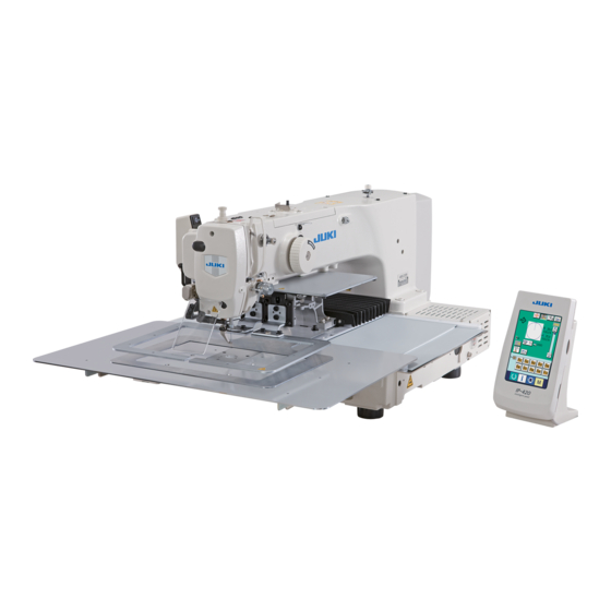
Summary of Contents for JUKI AMS-221EN Series
- Page 1 ® Computer-controlled, Cycle Machine With Input Function AMS-221EN Series ENGINEER’S MANUAL 40087241 No.E389-00...
- Page 2 PREFACE This Engineer’s Manual is written for the technical personnel who are responsible for the service and maintenance of the machine. The Instruction Manual for these machines intended for the maintenance personnel and operators at an apparel factory contains operating instruction in derail. And this manual describes “Standard Adjustment”, “Adjustment Procedures”, “Results of Improper Adjustment”, and other important information which are not covered in the Instruction Manual.
-
Page 3: Table Of Contents
CONTENTS 1. Specifications ......................1 2. Configuration ......................2 (1) Names of main unit ........................2 (2) IP-420 operation panel ......................3 3. Standard adjustment ....................(1) Adjustment of the throat plate auxiliary cover height ............4 (2) Adjustment of the feed bar auxiliary cover rail X ..............6 (3) Adjustment of the X movement top cover................ - Page 4 (49) Adjusting the needle thread clamp sensor ................ 74 (50) Adjustment of tilt machanism of the machine head............76 4. Memory switch ...................... 82 (1) Start and change ........................82 (2) Function list ..........................5. Supplemental remarks of each function number and explanation of each function ................
-
Page 5: Specifications
Lubricating oil JUKI NEW Defrix oil No. 2 (equivalent to ISO VG32) (Lubrication system) Grease 1. Penetration No. 2 lithium grease, 2. Templex N2, 3. Juki Grease A, 4. Juki Grease B (Caution)1. Sewing machine, Media Memory of pattern data •... -
Page 6: Configuration
2. Configuration (1) Names of main unit Machine head Air regulator Wiper switch Temporary stop switch Feeding frame Intermediate presser Thread stand Operation panel (IP-420) Power switch Control box Foot pedal – 2 –... -
Page 7: Operation Panel
(2) IP-420 operation panel (Front view) (Right side view) Touch panel • LCD display section READY key → Changeover of the data input screen and the sewing screen can be performed. INFORMATION key → Changeover of the data input screen and the information screen can be performed. -
Page 8: Standard Adjustment
3. Standard adjustment (1) Adjustment of the throat plate auxiliary cover height Standard Adjustment 1) 2516 Within 0.3mm 2) 3020 – 4 –... - Page 9 Adjustment Procedures Results of Improper Adjustment 1) 2516 o The feed plate is caught by the 1. Loosen 2 setscrews and 6 setscrews stepped part of the throat plate 2. Vertically move the throat plate auxiliary cover and the throat plate and the throat plate auxiliary cover auxiliary cover support to make adjustments so that the throat...
-
Page 10: Adjustment Of The Feed Bar Auxiliary Cover Rail X
(2) Adjustment of the feed base auxiliary cover rail X Standard Adjustment X movement bottom cover asm. X movement bottom cover asm. (3) Adjustment of the X movement top cover Standard Adjustment Auxiliary cover rail stop plate – 6 –... - Page 11 Adjustment Procedures Results of Improper Adjustment 1. Loosen 16 setscrews o If there is any rattling, this can be 2. Lightly push the feed base auxiliary cover rail X in the direction of a cause of noise. the arrow and adjust the X movement top cover asm. so that it can move smoothly without causing rattles.
-
Page 12: Main Shaft Connection/Disconnection
(4) Main shaft connection/disconnection Procedures of disassembling 1. Loosen the setscrew securing the main shaft counterbalance , and remove the taper screw 2. Loosen 2 setscrews (through the screwdriver hole A), 2 setscrews , and 2 setscrews On this occasion, loosen No. 2 setscrew first, and completely remove No. 1 setscrew from the flat part of the main shaft 3. - Page 13 Procedures of assembling 1. Insert the main shaft into the balancer , crank rod , bobbin winding drive wheel , hand pulley gear , intermediate presser eccentric cam , and the main shaft counterbalance in this order, and mount this assembly on the frame. 2.
-
Page 14: Removal Of Main Shaft Motor And Coupling
(5) Removal of main shaft motor and coupling Procedures of disassembling 1. For removal of the main shaft motor with the coupling, Loosen 2 setscrews on the main shaft side of the coupling , and remove 4 setscrews securing the motor. - Page 15 Procedures of assembling 1. For mounting the main shaft motor with the coupling, (1) Tighten 4 setscrews that securing the motor, and tighten 2 setscrews on the main shaft side of the coupling (2) The cords of the main shaft motor should be positioned in the lateral direction.
-
Page 16: Crank Rod Connection/Disconnection
(6) Crank rod connection/disconnection Procedures of disassembling 1. Loosen 3 setscrews and 2 setscrews . On this occasion, loosen No. 2 setscrews first, and completely disengage No. 1 setscrews from the flat section of the oscillator shaft 2. Pull out the oscillator shaft in the direction of Arrow A. - Page 17 Procedures of assembling 1. Mount the main shaft according to “3.-(4) Main shaft connection/disconnection”, and mount the crank rod unit 2. Adjust the clearance to 22.1 to 22.6 mm between the under cam of the crank rod unit and Face B (middle metal bearing mounting face) of the frame, and secure the cam with the setscrew (Apply No.
-
Page 18: Crank Balancer Positioning
(7) Crank balancer positioning Standard Adjustment [Rotating direction] When the needle bar lowers and the clearance between the needle bar connecting and needle bar lower bushing is 4.6 mm, 2 setscrews of the crank balancer becomes horizontal position. [Axial direction] Bring the main shaft eccentric cam into contact with the crank balancer 4.6mm... - Page 19 Adjustment Procedures Results of Improper Adjustment o If the mounting angle of the crank If the main shaft eccentric cam is not secured, the main shaft eccentric balancer is wrong, vibration should be positioned first. during sewing will be intensified. 1.
-
Page 20: Adjustment Of Intermediate Presser Cam
(8) Adjustment of intermediate presser cam Standard Adjustment Align Align (9) Adjustment of intermediate presser bar Standard Adjustment – 16 –... - Page 21 Adjustment Procedures Results of Improper Adjustment 1. Align the edge of the intermediate presser cam with the center of o Stitch skipping and poor tense the engraved point on the main shaft , align the engraved line on stitch may occur. the intermediate presser cam with the engraved point on the main shaft...
-
Page 22: Intermediate Presser Variable Connection/Disconnection
(10) Intermediate presser variable connection/disconnection Procedures of disassembling 1. Remove the presser adjusting screw . Then, remove the intermediate presser spring and the guide shaft. 2. Remove the intermediate presser auxiliary spring 3. Remove the stepscrews , and 4. Remove the stepscrew 5. - Page 23 Procedures of assembling 1. Fix the intermediate presser variable shaft to the intermediate presser variable arm by means of the 2 setscrews so that the length of the shaft section becomes 229.5mm. (Both setscrews should be adjusted level to the intermediate presser variable shaft 2.
-
Page 24: Intermediate Presser Variable Adjustments
(11) Intermediate presser variable adjustments Standard Adjustment Start the Test Mode I10 and press three times after the completion of origin search. Press twice after the completion of origin search. At that time, a value of 3.5 ± 0.2 shall be secured from the amount of rise of the presser bar (intermediate presser). - Page 25 Adjustment Procedures Results of Improper Adjustment 1. Start the test mode I10. o There will be a displacement 2. Step on the start pedal to perform the origin search. between the variable value of the 3. Press the button on the panel 3 times. intermediate presser lower 4.
-
Page 26: Intermediate Presser Drive Arm
(12) Intermediate presser drive arm Standard Adjustment * Refer to Instruction Manual, 4-7. Intermediate presser height. Close contact Intermediate presser bar – 22 –... - Page 27 Adjustment Procedures Results of Improper Adjustment 1. Turn ON the power supply and set the height of the intermediate o If there is no clearance, there will presser to 0mm. Turn OFF the power supply in the state that the be interference between the intermediate presser has been lowered.
-
Page 28: Lower Shaft Backlash Adjustment And Connection/Disconnection
(13) Lower shaft backlash adjustment and connection/disconnection Standard Adjustment 1. Size of lower shaft backlash is 0.01 to 0.1mm (throughout the circumference of the main shaft) at the tip of the driver . The shaft is required to rotate smoothly. 2. - Page 29 Adjustment Procedures Results of Improper Adjustment 1. Lower shaft backlash o If the backlash is excessive, the 1) Loosen 2 setscrews and 2 setscrews hook noise will be increased. 2) Turn the lower shaft rear metal in the direction of the arrow and adjust o If backlash is too small, the lower the backlash, keeping the metal to contact closely with Face A.
-
Page 30: Adjustment Of Hook Oil Amount
(15) Adjustment of hook oil amount Standard Adjustment (16) Shuttle connection / disconnection and oil wick piping Procedures of disassembling 1. Loosen the 5 setscrews 2. Remove the setscrew and pull the oil tank in the direction of the arrow A. 3. - Page 31 Adjustment Procedures Results of Improper Adjustment o If the amount of hook lubricant is 1. Loosen the setscrew and remove it. reduced too much, this can be a 2. When the adjusting screw is tightened, the quantity of oil can be cause of frictional wear of the regulated for the lubrication pipe left hook race plane or lock-up.
-
Page 32: Adjusting The Height Of The Needle Bar
(17) Adjusting the height of the needle bar Standard Adjustment Maker line for 134 (DP x 5) Maker line for 135 x 17 (DP x 17) (No. 140 or more (#22 or more)) Marker line for 135 x 17 (DP x 17) (No. - Page 33 Adjustment Procedures Results of Improper Adjustment If adjustments are carried out with * Turn ON the power once, and turn OFF the power again after the needle bar positioned too low: making the intermediate presser in the lowered state. o Feed timing causes mismatching 1.
-
Page 34: Hook Adjustment
(18) Hook adjustment Standard Adjustment Maker line for 134 (DP x 5) Maker line for 135 x 17 (DP x 17) (No. 140 or more (#22 or more)) Marker line for 135 x 17 (DP x 17) (No. 140 less than (#22 less than)) Maker line for Maker line for Maker line for... - Page 35 Adjustment Procedures Results of Improper Adjustment * Turn ON the power once, and turn OFF the power again after o If the shuttle height of the driver making the intermediate presser in the lowered state. does not match the tip position 1.
-
Page 36: Thread Trimmer Presser Lifter Cam Connection/Disconnection
(19) Thread trimmer presser lifter cam connection/disconnection Procedures of disassembling 1. Loosen 2 setscrews securing the presser lifter and thread trimmer cam (hereafter called “cam”) 2. Loosen the 2 setscrews and remove the sensor slit 3. Remove the 4 setscrews and take out the presser lifting motor in the direction of the arrow. - Page 37 Procedures of assembling 1. Apply a proper amount of grease (Juki Grease A) to the grooved cam block of the cam , the peripheral cam block, and the rollers of the presser bar lifter link and the thread trimmer link .
-
Page 38: Adjustment Of The Moving Knife And Counter Knife Position
(21) Adjustment of the moving knife and counter knife position Standard Adjustment Counter knife position : The clearance between the counter knife and the needle hole guide is 1.0mm. Moving knife position : Before thread trimmer operation (standby state), the distance from the throat plate front end to the tip of the thread cutter lever (small) is 18.5±0.5mm. - Page 39 Adjustment Procedures Results of Improper Adjustment 1. Counter knife position o If the clearance is less than Loosen the counter knife set screw to adjust the position. 1.0mm, thread may be cut by the counter knife blade when the 2. Moving knife position thread is pulled with the moving Loosen the screw to adjust the position.
-
Page 40: Second Thread Tension Connection / Disconnection
(23) Second thread tension connection / disconnection Procedures of disassembling 1. Loosen the set screw 2. Remove three setscrews and take out the thread tension cap 3. Remove the nut and the tension releasing pin adjusting collar . Then take out the thread tension disc pressing plate and three thread tension disc return springs 4. - Page 41 Procedures of assembling 1. When mounting the second thread tension , confirm in advance that the pin block of the AT link unit (front) is exactly settling in the hole of the thread tension pressing pin . If you try to mount the second thread tension forcedly with the pin area left disengaged, this may result in breakage in the thread tension pressing pin...
-
Page 42: At Unit Connection / Disconnection
(24) AT unit connection / disconnection Procedures of disassembling 1. Remove the setscrew of the AT link unit (front) and take out the second thread tension . ((24) Refer to “Second thread tension connection / disconnection.”) 2. Draw out the cotter pin from the pin block (H type) or (S type) of the AT link unit (rear) - Page 43 Procedures of assembling 1. For incorporating the AT solenoid unit into the system, run the solenoid cable from the rear of the AT solenoid unit to the rear end of the machine arm. Fix the AT solenoid unit to the arm’s setscrew hole as specified below. H type: Visual center of the arm’s setscrew hole S type: Visual center of the arm’s setscrew hole movement to the plane side slightly (Refer to “3.-(19) Floating amont of the thread tension disk”).
-
Page 44: Wiper Adjustment
(25) Wiper adjustment Standard Adjustment 1. When lowering the intermediate presser at the stop position after thread trimming (needle height from the top surface of throat plate is 17.7 mm.) and pressing wiper link section , adjust the clearance between the center of needle and the inside of V letter of the wiper to 10 mm. - Page 45 Adjustment Procedures Results of Improper Adjustment 1. Turn OFF the power after stopping the thread trimming, or turn ON o If the clearance between the wiper the threading switch and lower the intermediate presser and needle is too small, the (Caution) As for the height of needle when adjusting the wiper wiper comes in contact with the...
-
Page 46: Backlash Adjustment For The X Motor
(26) Backlash adjustment for the X motor Standard Adjustment Motor installing base (27) Backlash adjustment for the Y motor Standard Adjustment Flat section Flat section Y drive gear thrust bearing – 42 –... - Page 47 Adjustment Procedures Results of Improper Adjustment 1. Loosen 2 each of the setscrews and setscrews o If there is any backlash, needle 2. Press the X feed stepping motor in the direction of the arrow to entry accuracy is lowered. This reduce the backlash to zero.
-
Page 48: Adjustment Of The Tension Of The X Timing Belt
(28) Adjustment of the tension of the X timing belt Standard Adjustment (Example: 2516) 9.8N Belt tension mete Belt tension meter (measurement value) (set value) (Example: 2516) TENSION 003.4g/m 400.0N 025 mm/R 0315 mm – 44 –... - Page 49 Adjustment Procedures Results of Improper Adjustment o If the tension is excessive, it will 1. Move the X moving base to the left end (in the direction of the arrow A). cause timing belt breakage. 2. Tighten the adjusting screw and fix the nut so that the belt o If the tension is too low, it will...
-
Page 50: Adjustment Of The Tension Of The Y Timing Belt
(29) Adjustment of the tension of the Y timing belt Standard Adjustment (Example: 2516) 9.8N Belt tension meter Belt tension mete (set value) (measurement value) (Example: 2516) TENSION 003.4g/m 300.0N 025 mm/R 0190 mm – 46 –... - Page 51 Adjustment Procedures Results of Improper Adjustment o If the tension is excessive, it will 1. Move the X moving base to the rear side (in the direction of the arrow A). cause timing belt breakage. 2. Tighten the adjusting screw so that the belt tension attains 290 to o If the tension is too low, it will 310N.
-
Page 52: How To Remove Rattles From The Y Drive Shaft
(30) How to remove rattles from the Y drive shaft Standard Adjustment Flat section Flat section Flat section Y-LM guide Y-LM guide Y timing belt Y timing belt Y drive shaft thrust bearing (31) Phase adjustment for the Y timing belt Standard Adjustment –... - Page 53 Adjustment Procedures Results of Improper Adjustment 1. Align the Y drive shaft thrust collar with the flat section of the Y o If there is any rattling, this can be drive shaft . Then, tighten two setscrews a cause of feed error. 2.
-
Page 54: Adjustment Of The X-Y Mechanism
(32) Adjustment of the X-Y mechanism Standard Adjustment Make adjustments to the dimensions specified below. 70mm Butt Butt Face A Butt 300.8mm Face A 70mm 70mm Face B 3020 only – 50 –... - Page 55 Adjustment Procedures Results of Improper Adjustment How to install the Y-LM guide o If no parallelism is secured, this 1. Butt the Y-LM guide to the bed and fasten it with screws. can be a cause of feed error. 2. Adjust the distance to 192mm between the Y-LM guide and the Y- o If no parallelism is secured, LM guide...
-
Page 56: Pressure Adjustment For The Side Plate Bearing
(33) Pressure adjustment for the slide plate bearing Standard Adjustment When the presser foot slide plate is moved vertically and then the slide plate bearing comes in contact with the spring pin, the startup torque (slippage torque) will be 0.98 to 7.84N (100 to 800g). (SM6050660TP) The thinner side should be The thinner side should be... - Page 57 Adjustment Procedures Results of Improper Adjustment o If normal pressure is too strong, 1. Loosen the setscrew vertical movement of the presser 2. Lightly tighten the pressure adjusting screw and give a pressure cannot be accomplished normally. to the slide plate bearing .
-
Page 58: Initial Length Of The Presser Cylinder
(34) Initial length of the presser cylinder Standard Adjustment When the shaft section of the presser cylinder assumes a state of maximum suction, the center-to-center distance is 119.5 ± 0.3mm between the ø5 hole of the presser cylinder and the ø5 hole of the cylinder knuckle. - Page 59 Adjustment Procedures Results of Improper Adjustment 1. Tighten the nut o If the distance is greater than 2. Turn the cylinder knuckle and adjust the center-to-center distance 119.5 ± 0.3mm, the feeding frame to 119.5 ± 0.3mm. cannot attain the maximum rising 3.
-
Page 60: Adjustment Of The Speed Controller
(36) Adjustment of the speed controller Standard Adjustment Standard adjusting value of the speed controller for the presser cylinder 1. Loosen the nut and once turn the knob fully in Direction A. Then, turn this knob in Direction B by one turn and tighten the nut Standard adjusting value of the speed controller for the 2-step stroke cylinder 1. - Page 61 Adjustment Procedures Results of Improper Adjustment Make adjustments according to the standard adjusting values. o Too much noise is generated o To increase the vertical presser speed, turn the knob in Direction when the presser is lowered. o The presser does not rise. o To decrease the vertical presser speed, turn the knob in Direction –...
-
Page 62: Adjustment Of The Pressure Reducer
(37) Adjustment of the pressure reducer Standard Adjustment Standard adjusting value of the pressure reducer for the presser cylinder (left) 1. Loosen the nut and turn the knob to adjust the air pressure so that it is reduced to 0.13 to 0.15Mpa. Then, tighten the nut Standard adjusting value of the pressure reducer for the presser cylinder (right) 1. - Page 63 Adjustment Procedures Results of Improper Adjustment Make adjustments according to the standard adjusting values. o The presser cannot be lowered by o To reduce the pressure, turn the knob in Direction B. hand. o To raise the pressure, turn the knob in Direction A.
-
Page 64: Making The Origin Setting Gauge
(38) Making the origin setting gauge Standard Adjustment 3mm 3mm 37mm 37mm 4-M6 43mm 39mm 43mm 4-ø4 Origin marking (for 2516) Origin marking (for 3020) (39) Adjusting the X origin sensor Standard Adjustment When the feed is in the mechanical origin, align the tip of the needle with the lateral position of the engraved dot of the origin. - Page 65 Adjustment Procedures Results of Improper Adjustment 1. According to the illustration, produce an origin adjustment gauge and mount it on presser foot asm. left and right * To produce the gauge for AMS-221EN-3020, the parts specified below are required. Part No. Part name Q’ty 40032837...
-
Page 66: Adjusting The Y Origin Sensor
(40) Adjusting the Y origin sensor Standard Adjustment When the feed is in the mechanical origin, align the tip of the needle with the longitudinal position of the engraved dot of the origin. Sensor Y – 62 –... - Page 67 Adjustment Procedures Results of Improper Adjustment 1. Start the test mode I06. 2. When the pedal is trodden on, the feed moves to the mechanical origin and then stops. 3. Lower the needle and check the front-rear displacement from the engraved marking of the origin.
-
Page 68: Adjustment Of The Bobbin Winder Driving Wheel Position
(41) Adjustment of the bobbin winder driving wheel position Standard Adjustment The distance is 139.5 mm between the measuring plane of the bobbin winder driving wheel and the cover mounting plane of the sewing machine frame 139.5mm (42) Adjusting the bobbin winder amount Standard Adjustment The position of the bobbin winder lover is based on the standard that it is 14 mm apart from the bobbin... - Page 69 Adjustment Procedures Results of Improper Adjustment 1. Loosen the 2 setscrews to adjust the position (139.5mm) of the o If the distance of 139.5mm is insufficient, rubber ring wear may bobbin winder driving wheel and fix it with the 2 setscrews occur in the bobbin winder unit.
-
Page 70: Adjustment Of The Shuttle Upper Spring And Lower Thread Holder Position
(43) Adjustment of the shuttle upper spring and lower thread holder position Standard Adjustment 1. Shuttle upper spring : In regard to the right and left positioning, secure coincidence between the center of the needle and that of the groove width C. For the front-rear positioning, join the needle rear end and the corner block. - Page 71 Adjustment Procedures Results of Improper Adjustment 1. Remove the work feed bar, feed plate, and the throat plate. Adjust o If there is a front and rear displacement or a right and left the positioning of shuttle upper spring with the setscrews displacement, needle thread pcs.).
-
Page 72: Shape Of The Shuttle Race Ring
(45) Shape of the shuttle race ring Standard Adjustment If wear seems to be too much around the pointed tip of the inner hook, release the shuttle race ring confirm that the dimensions of the hatched area on the rear side are 0.3 x 8mm. (46) Adjustment of thread take-up spring Standard Adjustment Stroke : The movable distance of the needle thread when the needle thread is pulled in the direction... - Page 73 Adjustment Procedures Results of Improper Adjustment 1. If the dimensions of 0.3 x 8mm are not secured, retouching is re- quired with the aid of an oil stone. Dimension A Part No. Name of part Remarks (mm) 14103253 Shuttle race ring A Optional 14103352 Shuttle race ring B...
-
Page 74: Needle Thread Clamp Device Connection/Disconnection
(47) Needle thread clamp device connection/disconnection Procedures of disassembling 1. Remove the hinge screw * If the hinge screw cannot be seen from the open part of the needle thread clamp device , try to move the needle thread clamp connector link by hand in the direction of A or B. - Page 75 Procedures of assembling 1. Push the needle thread clamp device in the direction of A and fix it with the three set screws . Tighten the hinge screw 2. Attain the test mode I08. 3. Try to tread on the pedal for origin retrieval. 4.
-
Page 76: Adjusting The Needle Thread Clamp Notch
(48) Adjusting the needle thread clamp notch Standard Adjustment 1. Needle thread clamp notch R position • When the needle thread clamp link complete is pushed in Direction A and Part B of the needle thread clamp release plate and the needle thread clamp device begins to open, the distance between the needle thread clamp device and the needle thread clamp base... - Page 77 Adjustment Procedures Results of Improper Adjustment 1. Needle thread clamp notch R adjustment o If the distance is too long between the needle thread clamp 1) Loosen the two set screws the needle thread clamp base 2) Push the needle thread clamp link complete in Direction A so that the needle thread release timing the distance between the needle thread clamp device...
-
Page 78: Adjusting The Needle Thread Clamp Sensor
(49) Adjusting the needle thread clamp sensor Standard Adjustment When the needle thread clamp support plate complete is withdrawn by S: 3 to 4 pulses or H: 5 to 6 pulses from the needle thread clamp position (Caution 1., 2.) the clearance A toward the needle thread clamp becomes 0. - Page 79 Adjustment Procedures Results of Improper Adjustment In the first place, confirm that the setting value of the memory switch o If there are too many pulses used U069 is [0] for S Type and [1] for H Type. Since then, make the until the clearance A becomes 0, adjustments as specified below.
-
Page 80: Adjustment Of Tilt Machanism Of The Machine Head
(50) Adjustment of tilt mechanism of machine head Standard Adjustment 1. Adjustment of lifter bracket position Fix the lifter brackets A and B in four positions by means of screws , washers , spring washers and nuts X direction Y direction Check. - Page 81 Adjustment Procedures Results of Improper Adjustment In regard to the fixing positions of the lifter brackets A and B o According to the mounting well as the table, refer to the five points specified below and assembly position of the lifter bracket, the them while adjusting their forward, backwards, right, and left positions.
- Page 82 (50) Adjustment of tilt mechanism of machine head Standard Adjustment 2. Adjustment of the falling stopper position Make adjustments so that the long-groove section of the stopper plate enters the pin smoothly when the release lever is moved in Direction A. 3.
- Page 83 Adjustment Procedures Results of Improper Adjustment 2. Adjustment of the falling stopper position o The stopper does not work even Vertically adjust the stopper base where the stopper plate enters the pin though the release lever smoothly when the release lever is turned in Direction A and the turned in Direction A.
- Page 84 (50) Adjustment of tilt mechanism of machine head Standard Adjustment 4. Replacement of the gas spring When the sewing machine is lifted, the force of more than 20kg may be required in the tip of the head grip In such a case, there is possibility of gas leakage at the gas spring .
- Page 85 Fix them by means of the nut * Apply Juki Grease B (Part No. 10013640) to the shaft section of the hinge screw 6. Return the stopper release lever to its original position. (Turn it in the reverse direction of 1.) Then, the stopper is released.
-
Page 86: Memory Switch
4. Memory switch (1) Start and change To change the memory switch (level 2): The sewing machine operation can be changed by changing the setting of the memory switch. (1) To call up the screen showing the memory switch data (level 2) list: Hold down the switch for approx. -
Page 87: Function List
(2) Function list • Level 1 (Refer to the instruction manual for changing procedure.) Initial value Smallest Item Setting range change- 2516 2516 2516 2516 2516 2516 3020 able unit Maximum sewing speed 200 to 2800sti/min 100sti/min 2800 Sewing speed of 1st stitch 200 to 900sti/min 100sti/min (In case of with thread clamp) - Page 88 Initial value Smallest change- Item Setting range 2516 2516 able unit 2516 2516 2516 2516 3020 Thread tension of 1st stitch 0 to 200 (In case of without thread clamp) Thread tension changeover timing –5 to 2 –5 at the sewing start (In case of without thread clamp) Counter motion selection Sewing counter...
- Page 89 Initial value Smallest Item Setting range change- 2516 2516 able unit 2516 2516 2516 2516 3020 Presser goes up after moving at start of sewing Presser goes up immediately afterend of sewing Selection of feeding frame drive Presser goes up by pedal system after completion of sewing operation after moving —...
- Page 90 Initial value Smallest Item Setting range change- 2516 2516 able unit 2516 2516 2516 2516 3020 Selection of route of return to origin Linear reset by return to origin button Pattern returning — Origin retrieval → sewing start position Selection of bobbin winding speed 800 to 2000sti/min 100sti/min 1600 Valid/Invalid selection of wiper...
- Page 91 Initial value Smallest Item Setting range change- 2516 2516 able unit 2516 2516 2516 2516 3020 Selection of number of invalid stitches at the 0 to 15 stitches start of sewing of thread breakage detection Selection of number of invalid stitches during 0 to 15 stitches sewing of thread breakage detection 0: Solid presser...
- Page 92 Initial value Smallest Item Setting range change- 2516 2516 able unit 2516 2516 2516 2516 3020 0: Solid presser 1: Right/left separated presser (Without priority of right/left) 2: Right/left separated presser (In the order of right to left) 3: Right/left separated Feeding frame control presser (In the order Procedure setting for feeding frame...
- Page 93 Initial value Smallest Item Setting range change- 2516 2516 able unit 2516 2516 2516 2516 3020 Without Selection of the presence of pedal — SW2 latch With Without Selection of the presence of pedal — SW3 latch With Without Selection of the presence of pedal —...
- Page 94 Initial value Smallest Item Setting range change- 2516 2516 able unit 2516 2516 2516 2516 3020 Temporary stop, thread trimming Automatic thread operation — (Thread trimming with the use of Stop Manual thread trimmer (by pressing stop SW again) 2800sti/min/3.5mm Main motor X/Y feed synchronized control (speed/pitch) 2200sti/min/3.5mm...
- Page 95 Initial value Smallest Item Setting range change- 2516 2516 2516 2516 2516 2516 3020 able unit without Selection of presence of air pressure — detection With Setting limit range of the intermediate 0 to 7.0mm presser height Upper limit setting Without Selection of valid/invalid of needle —...
- Page 96 • Level 2 Initial value Smallest Item Setting range change- 2516 2516 able unit 2516 2516 2516 2516 3020 Selection of feeding frame lowering 100 to 1500pps 10pps 1500 speed at motor presser operation Selection of feeding frame rising 100 to 3000pps 10pps 3000 speed at motor presser operation...
- Page 97 Initial value Smallest Item Setting range change- 2516 2516 2516 2516 2516 2516 3020 able unit Up position Selection of wiper output timing when — setting upper dead point stop Upper dead point Setup of feed moving limit range 0 to 819mm +127 +152 +127...
- Page 98 Initial value Smallest Item Setting range change- 2516 2516 able unit 2516 2516 2516 2516 3020 Setup of feeding frame rising position 0: Full open at feeding frame control/sewing end (enabled only if lift of work 1: Stroke position — clamp foot is selected at sewing 2 to 99: Full open Nonuse...
- Page 99 Initial value Smallest Item Setting range change- 2516 2516 2516 2516 2516 2516 3020 able unit Rest time setup at the top position 0 to 100ms 10ms of jump command 0 to 10000ms 100ms Setup of timeout period of input command (0: No timeout) Ineffective...
- Page 100 Initial value Smallest Item Setting range change- 2516 2516 2516 2516 2516 2516 3020 able unit X-axis position of fixed refuge position –800.0 to 800.0mm 0.1mm Y-axis position of fixed refuge position –800.0 to 800.0mm 0.1mm When XY feed moving speed/origin 100 to 10000pps 10pps 10000...
- Page 101 Initial value Smallest Item Setting range change- 2516 2516 able unit 2516 2516 2516 2516 3020 No bank connection and barcode Bank mode end number 2 Valid/Invalid selection of bank and Bank mode end — barcode mode number 4 Bank mode end number 8 Bank mode end number 16...
- Page 102 Initial value Smallest Item Setting range change- 2516 2516 2516 2516 2516 2516 3020 able unit Common data setting of thread 0 to 200 tension standard value Common data setting for height standard 0 to 3.5 value of intermediate presser Sewing screen Selection of display screen when —...
- Page 103 Initial value Smallest Item Setting range change- 2516 2516 able unit 2516 2516 2516 2516 3020 Main shaft speed sensitivity during XY 1 to 15 feed operation Ineffective XY feed acceleration limit — Effective 0 to 7 Model classification 8 and above: Optional...
-
Page 104: Supplemental Remarks Of Each Function Number And Explanation Of Each Function
5. Supplemental remarks of each function number and explanation of each function (1) Feeding frame operational sequence setup For the AMS-221EN, it is possible to change the method of feeding frame and pedal operation by means of a memory switch. 1. - Page 105 [(5) List of feeding frame and pedal setup]. For air driving Setup Contents Preference Explanation United clamp – Lowered to the bottom by Pedal 1. Right/left separation Lowering enabled The right feeding frame is lowered to the bottom by clamp from the right or left Pedal 1 (right).The left feeding frame is lowered to the bottom by Pedal 2 (left).
- Page 106 3. Feeding frame lifting setup at the end of sewing Using the memory switch U037, it is possible to set up the timing for feeding frame lifting at the end of sewing. Setup Contents Explanation After the start of The feeding frame is lifted after the movement sewing reset from the end of sewing to the start of sewing.
- Page 107 6. Presser pedal setup Using the memory switches U084 to U087 below, it is possible to set up the method of pedal operation. U084 : Used to set up the method of pedal operation for Pedal 1. (Standard pedal, PK47 right) U085 : Used to set up the method of pedal operation for Pedal 2.
-
Page 108: Fixed Refuge Position Setup
(2) Fixed refuge position setup Irrespective of the second origin in the pattern data, a memory switch is available to set up the second origin (fixed refuge position) that is common to each pattern. When the use of the fixed refuge position has been set up with the memory switch K090, the fixed refuge position becomes enabled, which has been set up with the fixed refuge position Coordinate X of Memory Switch K117 and the fixed refuge position Coordinate Y of Memory Switch K118. -
Page 109: Bank Function Setup
(3) Bank function setup The bank function means a function of sewing effected through changeover to a pattern by an external signal, which is registered in multiple pattern buttons in cases of cassette discrimination and others. For sewing by the bank function, an external signal input is entered before the feeding frame is lowered at the time of pedal treading-on. - Page 110 (2) External input terminal setup The input terminal numbers to be used for the bank function are set up. 1) Bank function setup screen display K130 When the number of bank connection select terminals is preset for the memory switch data (Level 2), the bank function button (A) is displayed on the mode changeover screen.
- Page 111 When the bank function setup screen is closed and the data input screen is displayed, a pictograph (F) for indicating the ON status is displayed if the bank function is turned ON. When the key is pressed, the bank mode screen is displayed.
-
Page 112: Port I/O Setup
(4) Port I/O setup This sewing machine is provided with the machine control functions that are enabled only by the machine main body through the generation of signal outputs to the outside and the reception of signal inputs from the outside, without the intervention by any appropriative I/O unit and other devices. - Page 113 2. Output terminal setup Output No. Contents Explanation No output For the actuator Feeding frame 1 Feeding frame right lifting Feeding frame 2 Feeding frame left lifting Feeding frame 3 (Feeding frame right 2-stage stroke) Feeding frame 4 Feeding frame left 2-stage stroke (Intermediate presser) (Signal output) Air OFF...
- Page 114 Output No. Contents Explanation Bobbin status Bobbin key → Bobbin status Main unit input status Main unit input key → Main unit input status Pattern check status Pattern check, thread tension / intermediate presser height command setup Last mode status Last mode status (Sewing machine revolutions / output / XY / presser thread cutter / thread clamp / intermediate presser test mode) Presser SW input effective...
- Page 117 [Normal Status Diagram of the Port I/O] G: Second origin C: Midway stop O: Origin 57: Setting condition READY SW ON 58: Ready operation state 59: Ready state 60: Sewing state 61: Sewing forwarded 62: Sewing machine driving 63: Sewing start point reset 64: Midway stop 65: Sewing error display stop 66: Sewing temporary stop...
- Page 118 [Error Status Diagram of the Port I/O] 57: Setting condition 58: Ready operation state 59: Ready state 60: Sewing state 61: Sewing forwarded 62: Sewing machine driving 63: Sewing start point reset 64: Midway stop Reset SW ON Reset SW ON Reset SW ON Reset SW ON 65: Sewing error display stop...
- Page 119 [Miscellaneous Status Diagram of the Port I/O] 57: Setting condition Ready SW ON Ready SW ON Test sewing SW → Test sewing Ready SW ON Test sewing SW OFF 58: Ready operation state 59: Ready state 60: Sewing state 61: Sewing forwarded 62: Sewing machine driving 63: Sewing start point reset 64: Midway stop...
- Page 120 [Sewing Machine Driving Status Diagram of the Port I/O] 49: Needle upper position 50: Needle lower position 51: Needle upper dead point position 52: Needle lower dead point position 53: Thread trimming signal 50ms 54: During rotation 120ms 55: Sewing machine brake 120ms 102: Sewing machine start 103: Sewing machine stop...
- Page 121 3. Setup procedures 1) Display of the port I/O screen When the switch is continuously pressed for about 6 seconds and the page changeover button is pressed, the port I/O setup button (A) is displayed. When this button is pressed, the port I/O setup screen is displayed.
- Page 122 3) Port I/O setup To make output number setting, input number set- ting, and virtual I/O number setting, the setup button (G) is pressed to enter an input of the setting function number (H) in the selected terminal through the ten key (I). The signal type is selected from High (J) and Low (K).
-
Page 125: Simplified Program Setup
(5) Simplified program setup This machine is provided with the simplified program functions, which can make the programming of various addi- tional devices (stacker, unit, etc.) according to sewing machine operation. In conjunction with the port I/O output functions, modification into such additional devices can be carried out in the main unit of the sewing machine. 1. - Page 126 4. Operational Procedures (1) Simplified program selection screen display When the key is continuously pressed for 3 seconds, the simplified program button (A) is displayed on the mode changeover screen. When this button is pressed, the simplified program selec- tion screen is displayed. (2) Simplified program effective / ineffective The simplified program comes in five patterns.
- Page 127 In the simplified program editing screen, the editing step is selected with the use of the step forwarding button (D) and the step return button (E). For each selected step, it is possible to carry out command port I/ O setting and parameter setting. A maximum of 99 steps can be entered.
- Page 128 On the port setup screen, current setting items are dis- played at the top left of the screen. : Output information (High) setup screen : Output information (Low) setup screen : Input information (High) setup screen : Input information (Low) setup screen Using the page turning buttons (M, L), the displayed port type can be changed.
- Page 129 3) Parameter input Corresponding to the selected command, the param- eter input button is displayed. When the parameter input button (Q) is pressed, the parameter input screen is displayed. Enter a numerical input through the ten key (R) and press the Enter button (S).
- Page 130 5) Step deletion It is possible to delete the step that has been dis- played. When the step deletion button (V) is pressed, the deletion check screen is displayed. When the Enter button (W) is pressed, the displayed step is deleted and the step standing behind is shifted forward.
- Page 137 (8) Copy the simplified program to other sewing machines. The simplified program can be copied to other sewing machines through media. In regard to the method of operation, refer to the relevant Instruction Manual. The data to be copied come in the following contents put in a single file. PRO1 PRO2 PRO3...
-
Page 138: Version Display
(6) Version display 1. To display the version information screen: Hold down the key for 3 seconds to call up the version information button, (A) on the screen. Press this button to display the version information screen. The version information screen shows the version information of your sewing machine. -
Page 139: Keylock Setup
(7) Keylock setup 1. To call up the keylock screen: Hold down the key for about 6 seconds. The page shift button A is displayed on the upper part of the screen. Press the page shift button to dis- play the next page. Press the key lock button B to display the key lock setting screen. - Page 140 3. Close the modal screen and display the data in- put screen. Close the mode screen. The data input screen is displayed and pictograph E for indicating the key lock status is displayed on the right of pattern No. indication. Only the buttons available even in the state of key lock are displayed.
-
Page 141: Customize Function Setting Of Key Lock
(8) Customize function setting of key lock The key lock customize function is used for the free setting of disabled buttons in the state of key lock as described in “5.-(7) Key lock setup”. It is possible to disable operation and also set up the absolute deletion of button pictogram and numerals. - Page 142 (2) Selecting the customize confirmation screen Select the customize confirmation screen for the key lock. Customizable screen list for normal operation mode Button Screen Sewing shape data input screen (when selecting the user pattern) Sewing shape data input screen (when selecting the media pattern) Sewing shape data input screen (when selecting the di- rect pattern)
- Page 143 (3) Customize setup Hold down a button to disable the operation for about 1 second. The pictograph D to indicate the operation disabling setup is displayed at top left of the button. In actual operation, the setting state is displayed as shown in the figure E.
- Page 144 (4) Display of change destination screen When a change destination button is pressed, a change destination screen can be displayed. However, a change destination screen is not displayed even though a button of operation disabling setup or no-display setup is pressed. Press this button.
- Page 145 2. Batch customize In the key lock customize selection screen, batch customize is possible. (1) Press the button A for about 1 second. Buttons in all the changed screens are disabled and the customize setup conditions are saved. In addition, the pictogram “B” is displayed at top left of the pressed button (*Caution). The pictograph “B”...
- Page 146 3. Initializing the customize setup The customize setup can be initialized to the state of shipment from the factory. (1) Display of the initialize checking screen for the key lock customize Press the button A or button B in the key lock customize selection screen. The checking screen for the key lock customize initialization is displayed.
- Page 147 4. If the customize data are broken If the backup data disappear as a result of no use of the panel for a long time or the key lock customize data are destroyed for a certain reason, the screen specified below is displayed when the power switch is turned on. (1) When the backup data are available The key lock customize data are provided with the backup data.
-
Page 148: Communication Screens Of The Maintenance Personnel Level (Program Rewrite)
(9) Communication screens of the maintenance personnel level (Program rewrite) The data types allowed to be handled in the communication screens can differ according to the ordinarily used levels and the specific levels that are used by the maintenance personnel. 1. - Page 149 2. Reading/Writing of adjustment data and all sew- ing machine data (1) Display of the communication screen of the main- tenance personnel level When the key (A) is continuously pressed for 3 seconds, the top left image is turned into the orange color (B) and a communication screen of the mainte- nance personnel level is displayed.
- Page 150 (3) Program rewrite start When the start of communication button (H) is pressed, program rewriting is started. (Caution) Never turn off the power or open/shut the media cover during the work. Otherwise, the main body can be destroyed. Data deleting screen Data writing screen Ending screen When the ending screen is displayed, the replacement...
- Page 151 4. Use of media other than those packed together When the contents of the media packed together are going to be copied on another media, the media of the copying destination should be formatted with IP-420. Since then, the following directory configuration should be established with a personal computer.
-
Page 152: Information Screen At The Maintenance Personnel Level
(10) Information screen at the maintenance personnel level 1. Error history (1) To display the information screen at the mainte- nance personnel level: Hold down the information key, (A) for approx. 3 seconds in the switch sheet section on the data in- put screen to call up the information screen at the maintenance personnel level. - Page 153 2. Cumulative operating information (1) To call up the information screen at the mainte- nance personnel level: Hold down the information key , i for approx. 3 seconds in the switch sheet section on the data in- put screen to call up the information screen at the maintenance personnel level.
-
Page 154: Test Sewing Function
(11) Test sewing function Connecting your PC to the sewing machine allows you to perform test sewing based on data created with PM-1 (sewing data creating and editing software). IP-420 Data transmission P M - 1 P M - 1 Connect your PC and transmit data IP-420 to the sewing machine after creating it with PM-1, and IP-420 automati- cally shows the test sewing screen when the data input screen is called up. - Page 155 (3) Modification to data Press the button, A, B, or C to be changed to call up the numeric keypad. Enter a new value and press the enter button (D). (4) Test sewing Press the ready-to-go switch (E) to call up the test sewing screen.
- Page 156 2. Color chart indicating thread tension values An indicated needle positioning drawing varies with thread tensions adjusted for needle entry positions. The follow- ing chart shows the colors of lines for thread tensions. Thread tension Color 0 to 20 : Gray 21 to 40 : Purple 41 to 60...
-
Page 157: Test Mode
6. Test mode 1) Display of the check program screen When the key is continuously pressed for 3 seconds, the check program (A) is displayed on the screen. When this button is depressed, the check program screen is displayed. – 153 –... - Page 158 The check program comes in the ten items as specified below. Touch panel correction screen → The touch panel and button display positions are corrected. LCD check → Presence of any dot missing is checked for the liq- uid crystal display. Input signal check →...
- Page 159 2) Touch panel correction 1. Display of the touch panel correction screen When the touch panel correction button (A) of the check program screen is pressed, the touch panel correction screen is displayed. 2. Pressing the bottom left position Press the red circle (C) located at the bottom left of the screen.
- Page 160 4. Pressing the top left position Press the red circle (E) located at the top left of the screen. To complete correction, press the cancel button (B). 5. Pressing the top right position Press the red circle (F) located at the top left of the screen.
- Page 161 3) LCD check 1. Display of the LCD check screen When the LCD check button (A) is pressed on the check program screen, the LCD check screen is displayed. 2. Confirmation of LCD dot missing The LCD check screen is displayed only in one color. In this state, the LCD should be checked to freedom from dot missing.
- Page 162 4) Method of input signal check 1. Display of the input signal check screen When the input signal check button (A) is pressed on the check program screen, the sensor check screen is displayed. Input signal check In the input signal check screen, the input condi- tions of various sensors can be confirmed.
- Page 163 The sensors provide the following 43 types of conditions: Pictograph Contents of sensor Pictograph Contents of sensor DIPSW2-1 SDET sensor DIPSW2-2 Head fall SW DIPSW2-3 Air pressure SW DIPSW2-4 Thread breakage sensor SW Start SW (Pedal) X motor origin sensor Presser 1 SW (Pedal) Y motor origin sensor Presser 2 SW (Pedal)
- Page 164 Pictograph Contents of sensor Pictograph Contents of sensor External input 6 External input 12 External input 7 External input 13 External input 8 External input 14 External input 9 External input 15 External input 10 External input 16 External input 11 ∗...
- Page 165 5) Main motor rpm check 1. Display of the main motor rpm check screen When the main motor rpm check button (A) is pressed on the check program screen, the main motor rpm check screen is displayed. 2. Main motor operation and measured rpm value check Using the –/+ buttons (B, C), the rpm...
- Page 166 6) Method of output check 1. Display of the output check screen When the output check button (A) is pressed on the check program screen, the output check screen is displayed. 2. Output check The output check screen can be used for the output check of each position.
- Page 167 The output check display provides the following 17 types of positions: Pictograph Contents Pictograph Contents Wiper Air output 9 Air output 1 Air output 10 Air output 2 Air output 11 Air output 3 Air output 12 Air output 4 Air output 13 Air output 5 Air output 14...
- Page 168 7) Method of XY motor / origin sensor check 1. Display of the XY motor / origin sensor check screen When the XY motor / origin sensor check button (A) is pressed on the check program screen, the XY motor / origin sensor check screen is dis- played.
- Page 169 8) Method of presser and thread trimmer motor / origin sensor check Display of the presser and thread trimmer mo- tor / origin sensor check screen When the presser and thread trimmer motor / origin sensor check button (A) is pressed on the check program screen, the presser and thread trim- mer motor / origin sensor check screen is displayed.
- Page 170 9) Method of needle thread clamp motor / origin sen- sor check 1. Display of the needle thread clamp motor / origin sensor check screen is displayed. When the needle thread clamp motor / origin sensor check button (A) is pressed on the check program screen, the needle thread clamp motor / origin sensor check screen is displayed.
- Page 171 10) Method of continuous operation 1. Display of the continuous operation setup screen When the continuous operation button (A) is pressed on the check program screen, the continu- ous operation setup screen is displayed. 2. Continuous operation mode setup In the continuous operation setup screen, the con- tinuous operation mode is set up.
- Page 172 11) Method of intermediate presser motor / origin sensor check 1. Display of the intermediate presser motor / ori- gin sensor check screen When the intermediate presser motor / origin sensor check button (A) is pressed on the check program screen, the intermediate presser motor / origin sensor check screen is displayed.
-
Page 173: Printed Wiring Board And Dip Switch
7. Printed wiring board and dip switch (1) Various printed wiring boards 1) FLT-T board Single-phase 100V~120V 3-phase 200V~240V Pulse generation is carried out for the purposes of power supply rectification, noise reduction, and the detection of a CN1 : Power input ← Power switch momentary interruption In the signal-phase mode, the power supply is connected to... - Page 174 2) FLT-S board Single-phase 200V~240V Pulse generation is carried out for the purposes of power supply rectification, noise reduction, and the detection of a momentary interruption CN1: Power input ← Power switch S i n c e s i n g l e - p h a s e s p e c i f i c a t i o n s a r e adopted, the power supply is connected to Pins 4-5.
- Page 176 4) LED3 for SDC board error check No. of LED3 flashes Error description Display of operation panel Remarks Turn on Dimly turn on in ordinary state Main shaft motor lock E007 Failure in revolving for 2 seconds Error in phase Z E303 Failure in phase Z detection About 1.5 turns...
- Page 180 8) IP-420 Panel Board The color LCD driver circuit, backlight power source, CPU, memories, etc., are loaded for the management of inputs, manufacturing, and others. CN113: USB connector (host side) CN113: USB connector (function side) CN118: Connector for LCD VR2: BZ-1: Buzzer Variable resistor for contrast adjustment VR1:...
-
Page 181: Dipswitch Setup
(2) Dipswitch setup 1. All dipswitches on the SDC board are turned OFF. SDC board 2. All dipswitches on the MAIN board are turned OFF. MAIN board IP-420 Panel Board SW2: DIP SW2 SW1: DIPSW 1 (for production check) <Normal setting state> <Normal setting state>... -
Page 182: Table Of Exchanging Gauge Parts According To Sewing Specifications And Needle Size Used
8. Table of exchanging gauge parts according to sewing specifications and needle size used In accordance with the sewing condition, exchange the gauges referring to the following table. Sewing spec. S type when Knit. foundation H type when When thick and needle size used delivered. -
Page 183: Option List
9. Option list Name of parts Type Part No Size (mm) 1. needle hole guide Needle hole guide (A) for light- B242621000A øA=1.6 weight material (Specification S) Needle hole guide (B) for medium- B242621000B øA=2.0 weight material (Specification H) Needle hole guide (C) for knitwear B242621000C øA=1.6 (Option) - Page 184 Name of parts Type Part No Size (mm) 5. Feed plate blank Sheet A for work clamp (Velboren) B259522000A A x B x t (Velboren) 1,000 x 675 x 1 Sheet B for work clamp B259522000B A x B x t (Velboren) 1,000 x 675 x 3 Sheet C for work clamp...
- Page 185 Name of parts Type Part No Size (mm) 8. Blank for processing Outer frame right blank with knurl 40052339 A x B x t AMS-221EN-2516 229 x 169 x 4 Separated type outer frame blank 40052338 A x B x t without knurl 229 x 169 x 4 (Left and right are common.)
- Page 186 Name of parts Type Part No Size (mm) 10. One-touch clamp One-touch clamp asm. 40052330 AMS-221EN-2516 In addition, two pieces of slider asm. 40052525 and four pieces of slider installing screws SM6060550TP are required. 11. Slider Slider asm. 40052525 AMS-221EN-2516 Slider installing screws SM6060550TP When the external frame of...
- Page 187 Name of parts Type Part No Size (mm) 15. Reversal intermediate presser Reversal intermediate presser B4316220000 A x B x t installing base installing base B 8 x 24 x 15 This item is required when the reversal intermediate presser blank small B4319220000 is used.
- Page 188 Name of parts Type Part No Remarks 18. Pedal switch 3-step pedal (PK47) GPK470010AB Relay cable for 3-step pedal 40033875 2-step pedal (PK78) 40033831 19. Needle cooler 40092717 (When the crosswise wiper asm. 40035867 is used) – 184 –...
- Page 189 Name of parts Type Part No Remarks 20. Pedal SW cable set This is a kit intended to change (40040138) (Set Item No.) the tandem pedal (PK78) into the 3-switch pedal. Switch assembly 40040130 For further details, refer to [(1) Method of pedal switch cable set connections].
-
Page 190: Method Of Pedal Switch Cable Set Connections
(1) Method of pedal switch cable set connections 1. Parts Pedal switch cable set (Item No.: 40040138) Item name Item No. Quantity Presser micro switch plate 11102308 Micro switch setscrew SL4031691SC ∗ Switch assembly Limit switch HA001900000 Heat contraction tube ø5 (15mm) E8760452G00 Heat contraction tube ø... - Page 191 5. Operation control items o The moving switch does not function unless the right pedal is trodden first. o For more details, refer to [6. Switch mounting position diagram]. 6. Switch mounting position diagram. (Caution) The micro switch shall be mounted in parallel to the upper plane of the pedal.
-
Page 192: Maintenance
10. Maintenance (1) Replacing the fuse The machine uses the following three fuses: (SDC Board) For pulse motor power supply protection 5A (time-lag fuse) For solenoid and pulse motor power supply pro- tection 3.15A (time-lag fuse) For control power supply protection 2A (fast-blow type fuse) –... -
Page 193: Changing The Voltage Specification
(2) Changing the voltage specification It is adaptable to the voltage of single phase 100V to 120V/3-phase 200V to 240V by changing the voltage changeover connector mounted on FLT-T p.c.b. (Caution) When the changing procedure is wrong, the control box will be broken. So, be very careful. Changing procedure of the changeover connector 1. -
Page 194: Greasing• Lock-Tight Parts
2. Recommendable grease This sewing machine uses five types of grease as specified below. Juki Grease A and B are installed inside the 1 1 1 1 1 sewing machine. (Refer to “(5) Replenishing the designated place with grease” for more details.) * Use Lithium Type consistency No. -
Page 195: Parts To Which Grease • Locktight Is Applied
(4) Parts to which grease • Locktight is applied o FRAME & MISCELLANEOUS COVER COMPONENTS (3) ∗ ∗ ∗ ∗ ∗ A : JUKI Grease A C : Grease D : Templex ∗ ∗ ∗ ∗ ∗ : Locktight 241... - Page 196 MAIN SHAFT & NEEDLE BAR COMPONENTS A (Inside) A (Bothe sides) A (Inside) A : JUKI Grease A B : JUKI Grease B C : Grease – 192 –...
- Page 197 PRESSER MECHANISM & PRESSER VARIABLE COMPONENTS (1) ∗ B (Both sides) B (Both sides) A : JUKI Grease A B : JUKI Grease B ∗ : Lock-tight 241 – 193 –...
- Page 198 PRESSER MECHANISM & PRESSER VARIABLE COMPONENTS (2) B : JUKI Grease B C : Grease o WIPER MECHANISM COMPONENTS C : Grease – 194 –...
- Page 199 TENSION RELESASE & THREAD TENSION COMPONENTS C : Grease o SHUTTLE DRIVER SHAFT COMPONENTS A : JUKI Grease A – 195 –...
- Page 200 TENSION RELEASE & THREAD TRIMMER MECHANISM COMPONENTS A : JUKI Grease A C : Grease o THREAD CLAMP COMPONENTS C : Grease – 196 –...
- Page 201 o X-Y COMPONENTS (1) ∗ ∗ ∗ ∗ ∗ ∗ ∗ ∗ 3020 only E : Three-Bond 3060G ∗ : Lock-tight 241 F : Grease (for LM guide) It shall be applied to the V groove section on the side surface. –...
- Page 202 o X-Y COMPONENTS (2) ∗ ∗ ∗ ∗ ∗ ∗ ∗ ∗ ∗ ∗ ∗ ∗ ∗ ∗ ∗ ∗ ∗ ∗ ∗ ∗ ∗ ∗ ∗ ∗ ∗ ∗ ∗ ∗ ∗ ∗ ∗ ∗ ∗ ∗ ∗ ∗ ∗ ∗ ∗ ∗ ∗...
- Page 203 o CLOTH FEED MECHANISM COMPONENTS C : Grease D : Grease D – 199 –...
-
Page 204: Replenishing The Designated Places With Grease
(5) Replenishing the designated places with grease * Perform grease supplement when the errors below are displayed or once a year (either one which is earlier). If grease has decreased due to cleaning of the sewing machine or any other reasons, be sure to immediately add grease. - Page 205 (Caution) Do not use Grease A and Grease B with mixed. Be sure to use the specified grease without fail. The grease filling coupling and setscrew should be used when applying JUKI Grease B. They should bot be used for JUKI Grease A.
- Page 206 1. Open the frame cover to remove intermediate presser auxiliary spring B 2. Apply JUKI Grease A onto periphery of needle bar . Turn the sewing machine by hand to apply grease onto the entire periphery of the needle bar.
- Page 207 3) Points to be applied with JUKI Grease B (Caution) Use grease tube B (part number: 40013640) (in light violet) supplied with the unit for adding grease to any points other than the points specifies below. If any grease other than the specified one is used, the related components can be damaged.
- Page 208 4) Grease replenishment to the holder plate 1. Apply the Juki Grease B to the rear side of the holder plate – 204 –...
-
Page 209: Error Code List
11. Error code list Error code Display Description of error Display message How to recover Place of recovery E001 Data is initializes Data is initialized. Turn OFF (FROM of MAIN CPU) the power E007 Machine lock Machine is locked. Turn OFF Main shaft of the sewing machine the power fails to rotate due to some trouble... - Page 210 Error code Display Description of error Display message How to recover Place of recovery E017 Capacity over of sewing Capacity is insufficient. Possible to Previous machine memory (Machine) re-start after screen Machine memory capacity is reset. insufficient. E019 File size over Pattern data is too large.
- Page 211 Error code Display Description of error Display message How to recover Place of recovery E032 File interchanging error File cannot be read. Possible to Data input File cannot be read. re-start after screen after reset. E040 Sewing area over Move limit is exceeded. Possible to Sewing When the sewing area is...
- Page 212 Error code Display Description of error Display message How to recover Place of recovery E221 Grease-up error Important : Grease has run Possible to Data input At the time of operation of 120 out. re-start after screen million stitches Add grease. reset.
- Page 213 Error code Display Description of error Display message How to recover Place of recovery E434 Hardware error has occurred. Hardware error has Possible to Previous occurred. re-start after screen reset. E437 Function cannot be selected. Function cannot be Possible to Previous selected.
- Page 214 Error code Display Description of error Display message How to recover Place of recovery E811 Over voltage Input voltage is too high. Turn OFF When input power is more (Check input voltage.) the power. than the specified value. E813 Low voltage Input voltage is too low.
- Page 215 Error code Display Description of error Display message How to recover Place of recovery E915 Communication abnormality Communication is Turn OFF between operation panel and impossible. the power. MAIN CPU (Panel – MAIN p.c.b.) When abnormality occurs in data communication. E916 Communication abnormality Communication is...
- Page 216 Error code Display Description of error Display message How to recover Place of recovery E928 Thread trimming motor Thread trimming motor Turn OFF position slip error position is off. the power E930 Intermediate presser motor Intermediate presser Turn OFF position slip error motor position is off.
-
Page 217: Message List
12. Message list Message No. Display Display message Description M520 Erase confirmation of User’s pattern Erase is performed. OK? M521 Erase confirmation of pattern button Erase is performed. OK? M522 Erase confirmation cycle pattern Erase is performed. OK? M523 Erase confirmation of backup data Pattern data is not stored in memory. - Page 218 Message No. Display Display message Description M532 Overwriting confirmation of vector data on personal computer/M3 data/sewingstandard format data/ simplified program data Overwriting is performed. OK? M534 Overwriting confirmation of adjustment data of media and all machine data Overwriting is performed. OK? M535 Overwriting confirmation of adjustment data on personal...
- Page 219 Message No. Display Display message Description M546 Data corresponding to personal computer does not exist. Data does not exist. M547 Overwriting prohibition on pattern data Overwriting cannot be performed since data exists. M548 Overwriting prohibition on media data Overwriting cannot be performed since data exists.
- Page 220 Message No. Display Display message Description M653 During formatting Formatting is performed. M669 During data reading Data is being read. M670 During data writing Data is being written. M671 During data converting Data is being converted. – 216 –...
-
Page 243: Circuit Diagrams
14. Circuit diagrams (1) Block diagram (White) MOTOR CABLE 2 pedal 40083869 SUB P.C.B 3 pedal (White) THREAD HOLD MOTOR 2-phase 40085033 For Analog pedal MOTOR CABLE 40083865 (White) (Red) ENCODER CABLE 40083870 X FEED MOTOR Switch Input x 5 2-phase (Red) (Red) -
Page 244: Power Supply Circuit Diagram A
(2) Power supply circuit diagram A FLT-T BOARD SDC BOARD MAIN BOARD POWER SWITCH 200V CONNECTIONS White Green White Green Black Yellow Black White White Orange Black Black Black White Black Brown White Yellow – 240 –... -
Page 245: Power Supply Circuit Diagram B
(3) Power supply circuit diagram B FLT-T BOARD SDC BOARD MAIN BOARD POWER SWITCH 100V CONNECTIONS White Green/ Yellow Green White Gray Black Yellow Gray White Orange Black Black Black White Black Brown White Yellow – 241 –... -
Page 246: Power Supply Circuit Diagram C
(4) Power supply circuit diagram C FLT-S BOARD SDC BOARD MAIN BOARD POWER SWITCH White Green/ Green/Yellow Yellow White Brown Brown Yellow Light Blue Light Blue Orange Black Black Black White Black Brown White Yellow – 242 –... -
Page 247: Servo Motor Circuit Diagram
(5) Servo motor circuit diagram AC SERVO MOTOR SDC BOARD White (Drain line) Black Orange Blue Purple ENCODER Light Blue Pink Yellow Black White Green + Yellow – 243 –... -
Page 248: Sensor-Pedal Circuit Diagram
(6) Sensor-pedal circuit diagram (Red) X feed origin sensor (Yellow) White Y feed origin sensor Black (Black) Lifting the work clamp White foot origin sensor Black (Yellow) Brown MAIN BOARD Black BOARD Needle thread clamp Blue origin sensor Brown Needle thread clamp Black position sensor Blue... -
Page 249: Main•Panel Board Circuit Diagram
(7) MAIN•PANEL board circuit diagram MAIN BOARD PANEL BOARD – 245 –... -
Page 250: Motor•Solenoid Circuit Diagram
(8) Motor•solenoid circuit diagram MAIN BOARD CN39 (Yellow) CN40 (Red) White Yellow AT solenoid Blue X feed motor R = 13.8 Ω R = 1.05 Ω /1ø Black Orange CN47 (White) CN41 (White) Black Wiper solenoid Yellow Ω R = 5 Blue Y feed motor White... -
Page 251: Air System Circuit Diagram
(9) Air system circuit diagram Standard (united clamp) specifications 2-step presser specifications (with 2-step stroke) AMS-221ENSS-2516 AMS-221ENSL-2516 AMS-221ENSS-3020 AMS-221ENHL-2516 AMS-221ENHS-2516 AMS-221ENHS-3020 2-step stroke cylinder Feeding frame cylinder (left) Feeding frame cylinder (right) Feeding frame cylinder (left) Feeding frame cylinder (right) Solenoid valve for presser (right) Solenoid valve for... -
Page 252: Drawing Of The Table
15. Drawing of the table 30 drill 17 drill 2 x 11 drill 9 drill, 20depth conterbore depth 17 10 drill Top of table 2 x 3.5 drill, depth 10 3 drill, depth 8 4 x 11 drill +0.5 2 x 50 depth –0.5 2 x 2 drill,... - Page 253 ISO14001 : 2004 REG.NO.JSAE389 CM001 Juki Corporation operates an environmental management system to promote and conduct the following as the company engages in the research, development, design, sales, distribution,and maintenance of industrial sewing machines, household sewing machines, industrial robots, etc., and in the provision of sales and maintenance services...
Need help?
Do you have a question about the AMS-221EN Series and is the answer not in the manual?
Questions and answers