
Subscribe to Our Youtube Channel
Related Manuals for JUKI AMS-221EHL


Summary of Contents for JUKI AMS-221EHL
- Page 1 ® Computer-controlled, Cycle Machine With Input Function AMS-221E Series ENGINEER’S MANUAL 40049827 No.E374-02...
- Page 2 PREFACE This Engineer’s Manual is written for the technical personnel who are responsible for the service and maintenance of the machine. The Instruction Manual for these machines intended for the maintenance personnel and operators at an apparel factory contains operating instruction in derail. And this manual describes “Standard Adjustment”, “Adjustment Procedures”, “Results of Improper Adjustment”, and other important information which are not covered in the Instruction Manual.
-
Page 3: Table Of Contents
CONTENTS 1. Specifications ......................1 2. Configuration ......................2 (1) Names of main unit ........................2 (2) IP-410 operation panel ......................3 3. Standard adjustment ....................4 (1) Adjustment of the throat plate auxiliary cover height ............4 (2) Adjustment of the feed bar auxiliary cover rail X ..............6 (3) Adjustment of the X movement top cover................ - Page 4 (49) Adjusting the needle thread clamp sensor ................ 72 (50) Adjusting the needle thread clamp notch ................74 4. Memory switch ...................... 76 (1) Start and change ........................76 (2) Function list ..........................77 5. Supplemental remarks of each function number and explanation of each function ................
-
Page 5: Specifications
Lubricating oil JUKI NEW Defrix oil (equivalent to ISO VG32) (Lubrication system) Grease 1. Penetration No. 2 lithium grease, 2. Templex N2, 3. Juki Grease A, 4. Juki Grease B (Caution)1. EEP-ROM, Media Memory of pattern data • EEP-ROM : Max. 200 patterns (Max. 20,000 stitches/1pattern) •... -
Page 6: Configuration
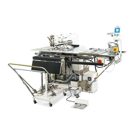
2. Configuration (1) Names of main unit Machine head Air regulator Wiper switch Temporary stop switch Feeding frame Intermediate presser Thread stand Operation panel (IP-410) Power switch Control box Foot pedal – 2 –... -
Page 7: Operation Panel
(2) IP-410 operation panel (Front view) (Right side view) Touch panel • LCD display section READY key → Changeover of the data input screen and the sewing screen can be performed. INFORMATION key → Changeover of the data input screen and the information screen can be performed. -
Page 8: Standard Adjustment
3. Standard adjustment (1) Adjustment of the throat plate auxiliary cover height Standard Adjustment 1) 2516 Within 0.3mm 2) 3020 – 4 –... - Page 9 Adjustment Procedures Results of Improper Adjustment 1) 2516 o The feed plate is caught by the 1. Loosen 2 setscrews and 6 setscrews stepped part of the throat plate 2. Vertically move the throat plate auxiliary cover and the throat plate and the throat plate auxiliary cover auxiliary cover support to make adjustments so that the throat...
-
Page 10: Adjustment Of The Feed Bar Auxiliary Cover Rail X
(2) Adjustment of the feed bar auxiliary cover rail X Standard Adjustment X movement bottom cover asm. X movement bottom cover asm. (3) Adjustment of the X movement top cover Standard Adjustment Auxiliary cover rail stop plate – 6 –... - Page 11 Adjustment Procedures Results of Improper Adjustment 1. Loosen 16 setscrews o If there is any rattling, this can be 2. Lightly push the feed bar auxiliary cover rail X in the direction of a cause of noise. the arrow and adjust the X movement top cover asm. so that it can move smoothly without causing rattles.
-
Page 12: Main Shaft Connection/Disconnection
(4) Main shaft connection/disconnection Procedures of disassembling 1. Loosen the setscrew securing the main shaft counterbalance , and remove the taper screw 2. Loosen 2 setscrews (through the screwdriver hole A), 2 setscrews , and 2 setscrews On this occasion, loosen No. 2 setscrew first, and completely remove No. 1 setscrew from the flat part of the main shaft 3. - Page 13 Procedures of assembling 1. Insert the main shaft into the balancer , crank rod , bobbin winding drive wheel , hand pulley gear , intermediate presser eccentric cam , and the main shaft counterbalance in this order, and mount this assembly on the frame. 2.
-
Page 14: Removal Of Main Shaft Motor And Coupling
(5) Removal of main shaft motor and coupling Procedures of disassembling 1. For removal of the main shaft with the coupling, Loosen 2 setscrews on the main shaft side of the coupling , and remove 4 setscrews securing the motor. 2. - Page 15 Procedures of assembling 1. For mounting the main shaft motor with the coupling, (1) Tighten 4 setscrews that securing the motor, and tighten 2 setscrews on the main shaft side of the coupling (2) The cords of the main shaft motor should be positioned in the lateral direction.
-
Page 16: Crank Rod Connection/Disconnection
(6) Crank rod connection/disconnection Procedures of disassembling 1. Loosen 3 setscrews and 2 setscrews . On this occasion, loosen No. 2 setscrews first, and completely disengage No. 1 setscrews from the flat section of the oscillator shaft 2. Pull out the oscillator shaft in the direction of Arrow A. - Page 17 Procedures of assembling 1. Mount the main shaft according to “3.-(4) Main shaft connection/disconnection”, and mount the crank rod unit 2. Adjust the clearance to 22.1 to 22.6 mm between the under cam of the crank rod unit and Face B (middle metal bearing mounting face) of the frame, and secure the cam with the setscrew (Apply No.
-
Page 18: Crank Balancer Positioning
(7) Crank balancer positioning Standard Adjustment [Rotating direction] When the needle bar lowers and the clearance between the needle bar connecting and needle bar lower bushing is 4.6 mm, 2 setscrews of the crank balancer becomes horizontal position. [Axial direction] Bring the main shaft eccentric cam into contact with the crank balancer 4.6mm... - Page 19 Adjustment Procedures Results of Improper Adjustment o If the mounting angle of the crank If the main shaft eccentric cam is not secured, the main shaft eccentric balancer is wrong, vibration should be positioned first. during sewing will be intensified. 1.
-
Page 20: Adjustment Of Intermediate Presser Cam
(8) Adjustment of intermediate presser cam Standard Adjustment Align Align (9) Adjustment of intermediate presser bar Standard Adjustment – 16 –... - Page 21 Adjustment Procedures Results of Improper Adjustment 1. Align the edge of the intermediate presser cam with the center of o Stitch skipping and poor tense the engraved point on the main shaft , align the engraved line on stitch may occur. the intermediate presser cam with the engraved point on the main shaft...
-
Page 22: Intermediate Presser Variable Connection/Disconnection
(10) Intermediate presser variable connection/disconnection Procedures of disassembling 1. Remove the presser adjusting screw . Then, remove the intermediate presser spring and the guide shaft. 2. Remove the intermediate presser auxiliary spring 3. Remove the stepscrews , and 4. Remove the stepscrew 5. - Page 23 Procedures of assembling 1. Fix the intermediate presser variable shaft to the intermediate presser variable arm by means of the 2 setscrews so that the length of the shaft section becomes 229.5mm. (Both setscrews should be adjusted level to the intermediate presser variable shaft 2.
-
Page 24: Intermediate Presser Variable Adjustments
(11) Intermediate presser variable adjustments Standard Adjustment Start the test mode I10 (IP-410). When is pressed twice after the completion of origin retrieval, there is coincidence between the center of left hole C in the arm and the second screws of the intermediate presser movable arm –... - Page 25 Adjustment Procedures Results of Improper Adjustment 1. Start the Test Mode I10 (IP-410). o There will be a displacement 2. Tread on the start pedal for origin retrieval, and make adjustments by between the variable value of the turning the sensor slit so that the lines combining the center of the intermediate presser lower intermediate presser lifting shaft...
-
Page 26: Intermediate Presser Drive Arm
(12) Intermediate presser drive arm Standard Adjustment * Refer to Instruction Manual, 4-7. Intermediate presser height. Close contact Intermediate presser bar – 22 –... - Page 27 Adjustment Procedures Results of Improper Adjustment 1. Turn ON the power supply and set the height of the intermediate o If there is no clearance, there will presser to 0mm. Turn OFF the power supply in the state that the be interference between the intermediate presser has been lowered.
-
Page 28: Lower Shaft Backlash Adjustment And Connection/Disconnection
(13) Lower shaft backlash adjustment and connection/disconnection Standard Adjustment 1. Size of lower shaft backlash is 0.1mm at the tip of the driver . The shaft is required to rotate smoothly. 2. Define the stop position of the lower shaft so that the setscrew settles almost in the center of the flat section... - Page 29 Adjustment Procedures Results of Improper Adjustment 1. Lower shaft backlash o If the backlash is excessive, the 1) Loosen 2 setscrews and 2 setscrews hook noise will be increased. 2) Turn the lower shaft rear metal in the direction of the arrow and adjust o If backlash is too small, the lower the backlash, keeping the metal to contact closely with Face A.
-
Page 30: Adjustment Of Hook Oil Amount
(15) Adjustment of hook oil amount Standard Adjustment (16) Shuttle connection / disconnection and oil wick piping Procedures of disassembling 1. Loosen the 5 setscrews 2. Remove the setscrew and pull the oil tank in the direction of the arrow A. 3. - Page 31 Adjustment Procedures Results of Improper Adjustment o If the amount of hook lubricant is 1. Loosen the setscrew and remove it. reduced too much, this can be a 2. When the adjusting screw is tightened, the quantity of oil can be cause of frictional wear of the regulated for the lubrication pipe left hook race plane or lock-up.
-
Page 32: Adjusting The Height Of The Needle Bar
(17) Adjusting the height of the needle bar Standard Adjustment Marker line for DP x 5 Marker line for DP x 17 (with needle count higher than #22) Marker line for DP x 17 (with needle count lower than #22) –... - Page 33 Adjustment Procedures Results of Improper Adjustment * Turn ON the power once, and turn OFF the power again after making the intermediate presser in the lowered state. 1. Bring the needle bar down to the lowest position, loosen the needle bar connection screw and align the upper engraved line on the...
-
Page 34: Hook Adjustment
(18) Hook adjustment Standard Adjustment : Marker line for DP x 5 needle : Marker line for DP x 17 needle (with needle count higher than #22) : Marker line for DP x 17 needle (with needle count lower than #22) DP x 17 needle DP x 17 needle When a DP x 5... - Page 35 Adjustment Procedures Results of Improper Adjustment * Turn ON the power once, and turn OFF the power again after making the intermediate presser in the lowered state. 1. Turn hand wheel by hand to ascend the needle bar Adjust so that lower marker line on the ascending needle bar aligns with the bottom end of the needle bar bushing lower 2.
-
Page 36: Thread Trimmer Presser Lifter Cam Connection/Disconnection
(19) Thread trimmer presser lifter cam connection/disconnection Procedures of disassembling 1. Loosen 2 setscrews securing the presser lifter and thread trimmer cam (hereafter called “cam”) 2. Loosen the 2 setscrews and remove the sensor slit 3. Remove the 4 setscrews and take out the presser lifting motor in the direction of the arrow. - Page 37 Procedures of assembling 1. Apply a proper amount of grease (Juki Grease A) to the grooved cam block of the cam , the peripheral cam block, and the rollers of the presser bar lifter link and the thread trimmer link .
-
Page 38: Adjusting The Thread Trimmer Sensor
(21) Adjusting the thread trimmer sensor Standard Adjustment After origin retrieval (Start Switch ON) in the test mode I07 (IP-410), press the + key 6 to 8 times until the thread trimmer sensor is turned OFF. (IP-410: Control panel display changed to →... - Page 39 Adjustment Procedures Results of Improper Adjustment 1. Start the test mode I07 (IP-410). o If the thread trimmer sensor 2. Tread on the pedal to perform origin retrieval for the thread trimmer changeover takes place outside cam. the range, the moving knife may (Confirm that the origin is in the correct position.
-
Page 40: Adjustment Of The Moving Knife And Counter Knife Position
(22) Adjustment of the moving knife and counter knife position Standard Adjustment Counter knife position : The clearance between the counter knife and the needle hole guide is 1.0mm. Moving knife position : Before thread trimmer operation (standby state), the distance from the throat plate front end to the tip of the thread cutter lever (small) is 18.5mm. - Page 41 Adjustment Procedures Results of Improper Adjustment 1. Counter knife position o If the clearance is less than Loosen the counter knife setscrew to adjust the position. 1.0mm, thread may be cut by the 2. Moving knife position counter knife blade when the Loosen the screw to adjust the position.
-
Page 42: Second Thread Tension Connection / Disconnection
(24) Second thread tension connection / disconnection Procedures of disassembling 1. Loosen the setscrew 2. Remove 3 setscrews and take out the thread tension cap 3. Remove the nut and the tension releasing pin adjusting collar . Then take out the thread tension disc pressing plate and three thread tension disc return springs 4. - Page 43 Procedures of assembling 1. When mounting the second thread tension , confirm in advance that the pin block of the AT link unit (front) is exactly settling in the hole of the thread tension pressing pin . If you try to mount the second thread tension forcedly with the pin area left disengaged, this may result in breakage in the thread tension pressing pin...
-
Page 44: At Unit Connection / Disconnection
(25) AT unit connection / disconnection Procedures of disassembling 1. Remove the setscrew of the AT link unit (front) and take out the second thread tension . ((24) Refer to “Second thread tension connection / disconnection.”) 2. Draw out the cotter pin from the pin block (H type) or (S type) of the AT link unit (rear) - Page 45 Procedures of assembling 1. For incorporating the AT solenoid unit into the system, run the solenoid cable from the rear of the AT solenoid unit to the rear end of the machine arm. 2. The center-to-center distance between the AT joints of the AT connector rod is 478.9 mm.
-
Page 46: Wiper Adjustment
(26) Wiper adjustment Standard Adjustment 1. When lowering the intermediate presser at the stop position after thread trimming (needle height from the top surface of throat plate is 17.7 mm.) and pressing wiper link section , adjust the clearance between the center of needle and the inside of V letter of the wiper to 10 mm. - Page 47 Adjustment Procedures Results of Improper Adjustment 1. Turn OFF the power after stopping the thread trimming, or turn ON o If the clearance between the wiper the threading switch and lower the intermediate presser and needle is too small, the (Caution) As for the height of needle when adjusting the wiper wiper comes in contact with the...
-
Page 48: Backlash Adjustment For The X Motor
(27) Backlash adjustment for the X motor Standard Adjustment Motor installing base (28) Backlash adjustment for the Y motor Standard Adjustment Flat section Flat section Y drive gear thrust bearing – 44 –... - Page 49 Adjustment Procedures Results of Improper Adjustment 1. Loosen 2 each of the setscrews and setscrews o If there is any backlash, needle 2. Press the X feed stepping motor in the direction of the arrow to entry accuracy is lowered. This reduce the backlash to zero.
-
Page 50: Tension Adjustment For The X Timing Belt
(29) Tension adjustment for the X timing belt Standard Adjustment 9.8N (30) Tension adjustment for the Y timing belt Standard Adjustment 9.8N – 46 –... - Page 51 Adjustment Procedures Results of Improper Adjustment 1. Move the X movement base to left side. o IIf the tension is too much, this can 2. Move the X movement base forward and backward, and let the cause destruction in the X timing right side hole of the bed coincide with the position of the adjusting belt screw...
-
Page 52: How To Remove Rattles From The Y Drive Shaft
(31) How to remove rattles from the Y drive shaft Standard Adjustment Flat section Flat section Flat section Y-LM guide Y-LM guide Y timing belt Y timing belt Y drive shaft thrust bearing (32) Phase adjustment for the Y timing belt Standard Adjustment –... - Page 53 Adjustment Procedures Results of Improper Adjustment 1. Align the Y drive shaft thrust collar with the flat section of the Y o If there is any rattling, this can be drive shaft . Then, tighten two setscrews a cause of feed error. 2.
-
Page 54: Adjustment Of The X-Y Mechanism
(33) Adjustment of the X-Y mechanism Standard Adjustment Make adjustments to the dimensions specified below. 70mm Butt Butt Face A Butt Face A 70mm – 50 –... - Page 55 Adjustment Procedures Results of Improper Adjustment How to install the Y-LM guide o If no parallelism is secured, this 1. Butt the Y-LM guide A to the bed and fasten it with screws. can be a cause of feed error. 2.
-
Page 56: Pressure Adjustment For The Face Plate Bearing
(34) Pressure adjustment for the face plate bearing Standard Adjustment When the presser foot face plate is moved vertically and then the face plate bearing comes in contact with the spring pin, the startup torque (slippage torque) will be 0.98 to 7.84N (100 to 800g). (SM6050660TP) The thinner side should be The thinner side should be... - Page 57 Adjustment Procedures Results of Improper Adjustment o If normal pressure is not applied, 1. Loosen the setscrew vertical movement of the presser 2. Lightly tighten the pressure adjusting screw and give a pressure cannot be accomplished normally. to the face plate bearing .
-
Page 58: Initial Length Of The Presser Cylinder
(35) Initial length of the presser cylinder Standard Adjustment When the shaft section of the presser cylinder assumes a state of maximum suction, the center-to-center distance is 119.5 ± 0.3mm between the ø5 hole of the presser cylinder and the ø5 hole of the cylinder knuckle. - Page 59 Adjustment Procedures Results of Improper Adjustment 1. Tighten the nut o If the distance is greater than 2. Turn the cylinder knuckle and adjust the center-to-center distance 119.5 ± 0.3mm, the feeding frame to 119.5 ± 0.3mm. cannot attain the maximum rising 3.
-
Page 60: Adjustment Of The Speed Controller
(37) Adjustment of the speed controller Standard Adjustment Standard adjusting value of the speed controller for the presser cylinder 1. Loosen the nut and once turn the knob fully in Direction A. Then, turn this knob in Direction B by one turn and tighten the nut Standard adjusting value of the speed controller for the 2-step stroke cylinder 1. - Page 61 Adjustment Procedures Results of Improper Adjustment Make adjustments according to the standard adjusting values. o Too much noise is generated o To increase the vertical presser speed, turn the knob in Direction when the presser is lowered. o The presser does not rise. o To decrease the vertical presser speed, turn the knob in Direction –...
-
Page 62: Adjustment Of The Pressure Reducer
(38) Adjustment of the pressure reducer Standard Adjustment Standard adjusting value of the pressure reducer for the presser cylinder (left) 1. Loosen the nut and turn the knob to adjust the air pressure so that it is reduced to 0.13 to 0.15Mpa. Then, tighten the nut Standard adjusting value of the pressure reducer for the presser cylinder (right) 1. - Page 63 Adjustment Procedures Results of Improper Adjustment Make adjustments according to the standard adjusting values. o The presser cannot be lowered by o To reduce the pressure, turn the knob in Direction B. hand. o To raise the pressure, turn the knob in Direction A.
-
Page 64: Making The Origin Setting Gauge
(39) Making the origin setting gauge Standard Adjustment 3mm 3mm 37mm 37mm 4-M6 43mm 39mm 43mm 4-ø4 Origin marking (for 2516) Origin marking (for 3020) (40) Adjusting the X origin sensor Standard Adjustment When the feed is in the mechanical origin, align the tip of the needle with the lateral position of the engraved dot of the origin. - Page 65 Adjustment Procedures Results of Improper Adjustment 1. According to the illustration, produce an origin adjustment gauge and mount it on presser foot asm. left and right * To produce the gauge for AMS-221E-3020, the parts specified below are required. Part No. Part name Q’ty 40032837...
-
Page 66: Adjusting The Y Origin Sensor
(41) Adjusting the Y origin sensor Standard Adjustment When the feed is in the mechanical origin, align the tip of the needle with the longitudinal position of the engraved dot of the origin. Sensor Y – 62 –... - Page 67 Adjustment Procedures Results of Improper Adjustment 1. Start the test mode I06 (IP-410). 2. When the pedal is trodden on, the feed moves to the mechanical origin and then stops. 3. Lower the needle and check the front-rear displacement from the engraved marking of the origin.
-
Page 68: Adjustment Of The Bobbin Winder Driving Wheel Position
(42) Adjustment of the bobbin winder driving wheel position Standard Adjustment The distance is 139.5 mm between the measuring plane of the bobbin winder driving wheel and the cover mounting plane of the sewing machine frame 139.5mm (43) Adjusting the bobbin winder amount Standard Adjustment The position of the bobbin winder lover is based on the standard that it is 14 mm apart from the bobbin... - Page 69 Adjustment Procedures Results of Improper Adjustment 1. Loosen the 2 setscrews to adjust the position (139.5mm) of the o If the distance of 139.5mm is insufficient, rubber ring wear may bobbin winder driving wheel and fix it with the 2 setscrews occur in the bobbin winder unit.
-
Page 70: Adjustment Of The Shuttle Upper Spring And Lower Thread Holder Position
(44) Adjustment of the shuttle upper spring and lower thread holder position Standard Adjustment 1. Shuttle upper spring : In regard to the right and left positioning, secure coincidence between the center of the needle and that of the groove width C. For the front-rear positioning, join the needle rear end and the corner block. - Page 71 Adjustment Procedures Results of Improper Adjustment 1. Remove the work feed bar, feed plate, and the throat plate. Adjust o If there is a front and rear displacement or a right and left the positioning of shuttle upper spring with the setscrews displacement, needle thread pcs.).
-
Page 72: Shape Of The Shuttle Race Ring
(46) Shape of the shuttle race ring Standard Adjustment If wear seems to be too much around the pointed tip of the inner hook, release the shuttle race ring confirm that the dimensions of the hatched area on the rear side are 0.3 x 8mm. (47) Adjustment of thread take-up spring Standard Adjustment Stroke : The movable distance of the needle thread when the needle thread is pulled in the direction... - Page 73 Adjustment Procedures Results of Improper Adjustment 1. If the dimensions of 0.3 x 8mm are not secured, retouching is re- quired with the aid of an oil stone. Dimension A Part No. Name of part Remarks (mm) 14103253 Shuttle race ring A Optional 14103352 Shuttle race ring B...
-
Page 74: Needle Thread Clamp Device Connection/Disconnection
(48) Needle thread clamp device connection/disconnection Procedures of disassembling 1. Remove the hinge screw * If the hinge screw cannot be seen from the open part of the needle thread clamp device , try to move the needle thread clamp connector link by hand in the direction of A or B. - Page 75 Procedures of assembling 1. Push the needle thread clamp device in the direction of A and fix it with the four setscrews . Tighten the hinge screw 2. Start the test mode I08. 3. Tread on the pedal for origin retrieval. 4.
-
Page 76: Adjusting The Needle Thread Clamp Sensor
(49) Adjusting the needle thread clamp sensor Standard Adjustment When the needle thread clamp support plate complete is withdrawn by 3 to 4 pulses from the needle thread clamp position (Caution 1., 2.) the clearance A toward the needle thread clamp becomes 0. - Page 77 Adjustment Procedures Results of Improper Adjustment In the first place, confirm that the setting value of the memory switch o If there are too many pulses used U69 is [0] for S Type and [1] for H Type. Since then, make the until the clearance A becomes 0, adjustments as specified below.
-
Page 78: Adjusting The Needle Thread Clamp Notch
(50) Adjusting the needle thread clamp notch Standard Adjustment 1. Needle thread clamp notch R position • When the needle thread clamp link complete is pressed in Direction A, and Part B of the needle thread clamp support plate complete and the needle thread clamp begins to open, the distance between the needle thread clamp... - Page 79 Adjustment Procedures Results of Improper Adjustment 1. Needle thread clamp notch R adjustment o If the distance is too long between 1) Loosen the 2 setscrews the needle thread clamp 2) Press the needle thread clamp link complete in Direction A so that the needle thread clamp base the distance between the needle thread clamp and the needle...
-
Page 80: Memory Switch
4. Memory switch (1) Start and change To change the memory switch (level 2): The sewing machine operation can be changed by changing the setting of the memory switch. For IP-410: (1) To call up the screen showing the memory switch data (level 2) list: Hold down the switch for approx. -
Page 104: Supplemental Remarks Of Each Function Number And Explanation Of Each Function
5. Supplemental remarks of each function number and explanation of each function (1) Feeding frame operational sequence setup For the AMS-221E, it is possible to change the method of feeding frame and pedal operation by means of a memory switch. 1. - Page 105 [(5) List of feeding frame and pedal setup]. For air driving Setup Contents Preference Explanation United clamp – Lowered to the bottom by Pedal 1. Right/left separation Lowering enabled The right feeding frame is lowered to the bottom by clamp from the right or left Pedal 1 (right).The left feeding frame is lowered to the bottom by Pedal 2 (left).
- Page 106 3. Feeding frame lifting setup at the end of sewing Using the memory switch U37, it is possible to set up the timing for feeding frame lifting at the end of sewing. Setup Contents Explanation After the start of The feeding frame is lifted after the movement sewing reset from the end of sewing to the start of sewing.
- Page 107 6. Presser pedal setup Using the memory switches U84 ~ U87 below, it is possible to set up the method of pedal operation. U84 : Used to set up the method of pedal operation for Pedal 1. (Standard pedal, PK47 right) U85 : Used to set up the method of pedal operation for Pedal 2.
-
Page 108: Fixed Refuge Position Setup
(2) Fixed refuge position setup Irrespective of the second origin in the pattern data, a memory switch is available to set up the second origin (fixed refuge position) that is common to each pattern. When the use of the fixed refuge position has been set up with the memory switch K90, the fixed refuge position becomes enabled, which has been set up with the fixed refuge position Coordinate X of Memory Switch K117 and the fixed refuge position Coordinate Y of Memory Switch K118. -
Page 109: Bank Function Setup
(3) Bank function setup The bank function means a function of sewing effected through changeover to a pattern by an external signal, which is registered in multiple pattern buttons in cases of cassette discrimination and others. For sewing by the bank function, an external signal input is entered before the feeding frame is lowered at the time of pedal treading-on. - Page 110 (2) External input terminal setup The input terminal numbers to be used for the bank function are set up. 1) Bank function setup screen display When the number of K130 bank connection select terminals is preset for the memory switch data (Level 2), the bank function button (A) is displayed on the mode changeover screen.
- Page 111 When the bank function setup screen is closed and the data input screen is displayed, a pictograph (F) AMS-221E for indicating the ON status is displayed if the bank function is turned ON. When the key is pressed, the bank mode screen is displayed.
- Page 112 Relationship between bank input terminals and bank numbers Input terminal Input terminal Input terminal Input terminal Bank number Bank number Bank number Bank number H H H H Bank No. 1 Bank No. 5 Bank No. 9 Bank No. 13 H H H Bank No.
-
Page 113: Port I/O Setup
(4) Port I/O setup This sewing machine is provided with the machine control functions that are enabled only by the machine main body through the generation of signal outputs to the outside and the reception of signal inputs from the outside, without the intervention by any appropriative I/O unit and other devices. - Page 114 2. Output terminal setup Output No. Contents Explanation No output For the actuator Feeding frame 1 Feeding frame right lifting Feeding frame 2 Feeding frame left lifting Feeding frame 3 (Feeding frame right 2-stage stroke) Feeding frame 4 Feeding frame left 2-stage stroke (Intermediate presser) (Signal output) Void...
- Page 115 Output No. Contents Explanation Bobbin status Bobbin key → Bobbin status Main unit input status Main unit input key → Main unit input status Pattern check status Pattern check, thread tension / intermediate presser height command setup Test mode status Test mode status (Sewing machine revolutions / output / XY / presser thread cutter / thread clamp / intermediate presser test mode) Presser SW input effective...
- Page 116 [Normal Status Diagram of the Port I/O] G: Second origin C: Midway stop O: Origin 57: Setting condition READY SW ON 58: Ready operation state 59: Ready state 60: Sewing state 61: Sewing forwarded 62: Sewing machine driving 63: Sewing start point reset 64: Midway stop 65: Sewing error display stop 66: Sewing temporary stop...
- Page 117 [Error Status Diagram of the Port I/O] 57: Setting condition 58: Ready operation state 59: Ready state 60: Sewing state 61: Sewing forwarded 62: Sewing machine driving 63: Sewing start point reset 64: Midway stop Reset SW ON Reset SW ON Reset SW ON Reset SW ON 65: Sewing error display stop...
- Page 118 [Miscellaneous Status Diagram of the Port I/O] 57: Setting condition Ready SW ON Ready SW ON Test sewing SW → Test sewing Ready SW ON Test sewing SW OFF 58: Ready operation state 59: Ready state 60: Sewing state 61: Sewing forwarded 62: Sewing machine driving 63: Sewing start point reset 64: Midway stop...
- Page 119 [Sewing Machine Driving Status Diagram of the Port I/O] 49: Needle upper position 50: Needle lower position 51: Needle upper dead point position 52: Needle lower dead point position 53: Thread trimming signal 50ms 54: During rotation 120ms 55: Sewing machine brake 120ms 102: Sewing machine start 103: Sewing machine stop...
- Page 120 3. Setup procedures 1) Display of the port I/O screen When the switch is continuously pressed for about 6 seconds and the page changeover button is pressed, the port I/O setup button (A) is displayed. When this button is pressed, the port I/O setup screen is displayed.
- Page 121 3) Port I/O setup To make output number setting, input number set- ting, and virtual I/O number setting, the setup button (G) is pressed to enter an input of the setting function number (H) in the selected terminal through the ten key (I). The signal type is selected from High (J) and Low (K).
-
Page 124: Simplified Program Setup
(5) Simplified program setup This machine is provided with the simplified program functions, which can make the programming of various addi- tional devices (stacker, unit, etc.) according to sewing machine operation. In conjunction with the port I/O output functions, modification into such additional devices can be carried out in the main unit of the sewing machine. 1. - Page 125 4. Operational Procedures (1) Simplified program selection screen display When the key is continuously pressed for 3 seconds, the simplified program button (A) is displayed on the mode changeover screen. When this button is pressed, the simplified program selec- tion screen is displayed. (2) Simplified program effective / ineffective The simplified program comes in five patterns.
- Page 126 In the simplified program editing screen, the editing step is selected with the use of the step forwarding button (D) and the step return button (E). For each selected step, it is possible to carry out command port I/ O setting and parameter setting. A maximum of 99 steps can be entered.
- Page 127 On the port setup screen, current setting items are dis- played at the top left of the screen. : Output information (High) setup screen : Output information (Low) setup screen : Input information (High) setup screen : Input information (Low) setup screen Using the page turning buttons (M, L), the displayed port type can be changed.
- Page 128 3) Parameter input Corresponding to the selected command, the param- eter input button is displayed. When the parameter input button (Q) is pressed, the parameter input screen is displayed. Enter a numerical input through the ten key (R) and press the Enter button (S).
- Page 129 5) Step deletion It is possible to delete the step that has been dis- played. When the step deletion button (V) is pressed, the deletion check screen is displayed. When the Enter button (W) is pressed, the displayed step is deleted and the step standing behind is shifted forward.
-
Page 136: Version Display
(6) Version display 1. To display the version information screen: Hold down the key for 3 seconds to call up the version information button, (A) on the screen. Press this button to display the version information screen. The version information screen shows the version information of your sewing machine. -
Page 137: Keylock Setup
(7) Keylock setup 1. To call up the keylock screen: Hold down the key for 3 seconds to call up the keylock button, (A) on the screen. Press this button to display the keylock setting screen. The current status appears on the keylock button. : Keylock is inactivated. -
Page 138: Communication Screens Of The Maintenance Personnel Level (Program Rewrite)
(8) Communication screens of the maintenance personnel level (Program rewrite) The data types allowed to be handled in the communication screens can differ according to the ordinarily used levels and the specific levels that are used by the maintenance personnel. 1. - Page 139 2. Reading/Writing of adjustment data and all sew- ing machine data (For the IP-410) (1) Display of the communication screen of the main- tenance personnel level When the key (A) is continuously pressed for 3 seconds, the top left image is turned into the orange color (B) and a communication screen of the mainte- nance personnel level is displayed.
- Page 140 (3) Program rewrite start When the start of communication button (H) is pressed, program rewriting is started. (Caution) Never turn off the power or open/shut the media cover during the work. Otherwise, the main body can be destroyed. Data deleting screen Data writing screen Ending screen When the ending screen is displayed, the replacement...
- Page 141 4. Use of media other than those packed together When the contents of the media card packed together are going to be copied on another media card, the media card of the copying destination should be formatted with IP410. Since then, the following directory configuration should be established with a personal computer.
-
Page 142: Information Screen At The Maintenance Personnel Level
(9) Information screen at the maintenance personnel level 1. Error history (1) To display the information screen at the mainte- nance personnel level: Hold down the information key, (A) for approx. 3 seconds in the switch sheet section on the data in- put screen to call up the information screen at the maintenance personnel level. - Page 143 2. Cumulative operating information (1) To call up the information screen at the mainte- nance personnel level: Hold down the information key , i for approx. 3 seconds in the switch sheet section on the data in- put screen to call up the information screen at the maintenance personnel level.
-
Page 144: Test Sewing Function
(10) Test sewing function Connecting your PC to the sewing machine allows you to perform test sewing based on data created with PM-1 (sewing data creating and editing software). IP410 IP410 Data transmission P M - 1 P M - 1 Connect your PC and transmit data to the sewing machine after creating it with PM-1, and IP-410 automatically shows the test sewing screen when the data input screen is called up. - Page 145 (3) Modification to data Press the button, A, B, or C to be changed to call up the numeric keypad. Enter a new value and press the enter button (D). (4) Test sewing Press the ready-to-go switch (E) to call up the test sewing screen.
- Page 146 2. Color chart indicating thread tension values An indicated needle positioning drawing varies with thread tensions adjusted for needle entry positions. The follow- ing chart shows the colors of lines for thread tensions. Thread tension Color 0 to 20 : Gray 21 to 40 : Purple 41 to 60...
-
Page 147: Test Mode
6. Test mode 1) Display of the check program screen When the key is continuously pressed for 3 seconds, the check program (A) is displayed on the screen. When this button is depressed, the check program screen is displayed. The check program comes in the ten items as specified below. - Page 148 Presser and thread trimmer motor / origin sen- sor check → The status of inching operation of the presser and thread trimmer motor, operation of origin retrieval, and the presser origin and presser sensor is dis- played. Needle thread clamp motor / origin sensor check →...
- Page 149 2) Touch panel correction 1. Display of the touch panel correction screen When the touch panel correction button (A) of the check program screen is pressed, the touch panel correction screen is displayed. 2. Pressing the bottom left position Press the red circle (C) located at the bottom left of the screen.
- Page 150 4. Pressing the top left position Press the red circle (E) located at the top left of the screen. To complete correction, press the cancel button (B). 5. Pressing the top right position Press the red circle (F) located at the top left of the screen.
- Page 151 3) LCD check 1. Display of the LCD check screen When the LCD check button (A) is pressed on the check program screen, the LCD check screen is displayed. 2. Confirmation of LCD dot missing The LCD check screen is displayed only in one color. In this state, the LCD should be checked to freedom from dot missing.
- Page 152 4) Method of input signal check 1. Display of the input signal check screen When the input signal check button (A) is pressed on the check program screen, the sensor check screen is displayed. Input signal check In the input signal check screen, the input condi- tions of various sensors can be confirmed.
- Page 153 The sensors provide the following 43 types of conditions: Pictograph Contents of sensor Pictograph Contents of sensor DIPSW2-1 SDET sensor DIPSW2-2 Head fall SW DIPSW2-3 Air pressure SW DIPSW2-4 Thread breakage sensor SW Start SW (Pedal) X motor origin sensor Presser 1 SW (Pedal) Y motor origin sensor Presser 2 SW (Pedal)
- Page 154 Pictograph Contents of sensor Pictograph Contents of sensor External input 6 External input 12 External input 7 External input 13 External input 8 External input 14 External input 9 External input 15 External input 10 External input 16 External input 11 –...
- Page 155 5) Main motor rpm check 1. Display of the main motor rpm check screen When the main motor rpm check button (A) is pressed on the check program screen, the main motor rpm check screen is displayed. 2. Main motor operation and measured rpm value check Using the –/+ buttons (B, C), the rpm...
- Page 156 6) Method of output check 1. Display of the output check screen When the output check button (A) is pressed on the check program screen, the output check screen is displayed. 2. Output check The output check screen can be used for the output check of each position.
- Page 157 The output check display provides the following 17 types of positions: Pictograph Contents Pictograph Contents Wiper Air output 9 Air output 1 Air output 10 Air output 2 Air output 11 Air output 3 Air output 12 Air output 4 Air output 13 Air output 5 Air output 14...
- Page 158 7) Method of XY motor / origin sensor check 1. Display of the XY motor / origin sensor check screen When the XY motor / origin sensor check button (A) is pressed on the check program screen, the XY motor / origin sensor check screen is dis- played.
- Page 159 8) Method of presser and thread trimmer motor / origin sensor check Display of the presser and thread trimmer mo- tor / origin sensor check screen When the presser and thread trimmer motor / origin sensor check button (A) is pressed on the check program screen, the presser and thread trim- mer motor / origin sensor check screen is displayed.
- Page 160 9) Method of needle thread clamp motor / origin sen- sor check 1. Display of the needle thread clamp motor / origin sensor check screen is displayed. When the needle thread clamp motor / origin sensor check button (A) is pressed on the check program screen, the needle thread clamp motor / origin sensor check screen is displayed.
- Page 161 10) Method of continuous operation 1. Display of the continuous operation screen When the continuous operation button (A) is pressed on the check program screen, the continu- ous operation screen is displayed. 2. Continuous operation In the continuous operation screen, the continuous operation mode is set up.
- Page 162 11) Method of intermediate presser motor / origin sensor check 1. Display of the intermediate presser motor / ori- gin sensor check screen When the intermediate presser motor / origin sensor check button (A) is pressed on the check program screen, the intermediate presser motor / origin sensor check screen is displayed.
-
Page 163: Printed Wiring Board And Dip Switch
7. Printed wiring board and dip switch (1) Various printed wiring boards 1) FLT-T board Single-phase 100V~120V 3-phase 200V~240V Pulse generation is carried out for the purposes of power supply rectification, noise reduction, and the detection of a CN1 : Power input ← Power switch momentary interruption In the signal-phase mode, the power supply is connected to... - Page 164 2) FLT-S board Single-phase 200V~240V Pulse generation is carried out for the purposes of power supply rectification, noise reduction, and the detection of a momentary interruption CN1: Power input ← Power switch S i n c e s i n g l e - p h a s e s p e c i f i c a t i o n s a r e adopted, the power supply is connected to Pins 4-5.
- Page 166 4) LED3 for SDC board error check No. of LED3 flashes Error description Display of operation panel Remarks Turn on Dimly turn on in ordinary state Main shaft motor lock E007 Failure in revolving for 2 seconds Error in phase Z E303 Failure in phase Z detection About 1.5 turns...
-
Page 170: Dipswitch Setup
(2) Dipswitch setup 1. The penetration force is increased when “4” of SDC board Dipswitch SW1 is turned ON on the SDC board 2. If the penetration force is insufficient for thick materi- als, this switch should be turned ON. 3. -
Page 171: Table Of Exchanging Gauge Parts According To Sewing Specifications And Needle Size Used
8. Table of exchanging gauge parts according to sewing specifications and needle size used In accordance with the sewing condition, exchange the gauges referring to the following table. Sewing spec. S type when Knit. foundation H type when When thick and needle size used delivered. -
Page 172: Option List
9. Option list Name of parts Type Part No Size (mm) 1. needle hole guide Needle hole guide (A) for light- B242621000A øA=1.6 weight material (Specification S) Needle hole guide (B) for medium- B242621000B øA=2.0 weight material (Specification H) Needle hole guide (C) for knitwear B242621000C øA=1.6 (Option) - Page 173 Name of parts Type Part No Size (mm) 5. Feed plate blank Sheet A for work clamp (Velboren) B259522000A A x B x t (Velboren) 1,000 x 675 x 1 Sheet B for work clamp B259522000B A x B x t (Velboren) 1,000 x 675 x 3 Sheet C for work clamp...
- Page 174 Name of parts Type Part No Size (mm) 8. Blank for processing Outer frame right blank with knurl 40052339 A x B x t AMS-221E-2516 229 x 169 x 4 Separated type outer frame blank 40052338 A x B x t without knurl 229 x 169 x 4 (Left and right are common.)
- Page 175 Name of parts Type Part No Size (mm) 10. One-touch clamp One-touch clamp asm. 40052330 AMS-221E-2516 In addition, two pieces of slider asm. 40052525 and four pieces of slider installing screws SM6060550TP are required. 11. Slider Slider asm. 40052525 AMS-221E-2516 Slider installing screws SM6060550TP When the external frame of...
- Page 176 Name of parts Type Part No Size (mm) 15. Reversal intermediate presser Reversal intermediate presser B4316220000 A x B x t installing base installing base B 8 x 24 x 15 This item is required when the reversal intermediate presser blank small B4319220000 is used.
- Page 177 Name of parts Type Part No Remarks 18. Pedal switch 3-step pedal (PK47) GPK470010AB Relay cable for 3-step pedal 40033875 2-step pedal (PK78) 40033831 19. Needle cooler 40035692 – 173 –...
- Page 178 Name of parts Type Part No Remarks 20. Pedal SW cable set This is a kit intended to change (40040138) (Set Item No.) the tandem pedal (PK78) into the 3-switch pedal. Switch assembly 40040130 For further details, refer to [(1) Method of pedal switch cable set connections].
-
Page 179: Method Of Pedal Switch Cable Set Connections
(1) Method of pedal switch cable set connections 1. Parts Pedal switch cable set (Item No.: 40040138) Item name Item No. Quantity Presser micro switch plate 11102308 Micro switch setscrew SL4031691SC ∗ Switch assembly Limit switch HA001900000 Heat contraction tube ø5 (15mm) E8760452G00 Heat contraction tube ø... - Page 180 5. Operation control items o The moving switch does not function unless the right pedal is trodden first. o For more details, refer to [6. Switch mounting position diagram]. 6. Switch mounting position diagram. (Caution) The micro switch shall be mounted in parallel to the upper plane of the pedal.
-
Page 181: Maintenance
10. Maintenance (1) Replacing the fuse The machine uses the following three fuses: (SDC Board) For pulse motor power supply protection 15A(time-lag fuse) For solenoid and pulse motor power supply pro- tection 3.15A (time-lag fuse) For control power supply protection 2A (fast-blow type fuse) –... -
Page 182: Changing The Voltage Specification
(2) Changing the voltage specification It is adaptable to the voltage of single phase 100V to 120V/3-phase 200V to 240V by changing the voltage changeover connector mounted on FLT-T p.c.b. (Caution) When the changing procedure is wrong, the control box will be broken. So, be very careful. Changing procedure of the changeover connector 1. -
Page 183: Application Of Grease And Locktight
10g tube JUKI Part No.: 40006323 500g (IE-22) JUKI Part No.: 23640204 JUKI Grease B •••• Used, in particular, for the specific areas with highly loaded parts. Important: this grease must be replenished at the specified intervals of period, according to “(5) Grease-up procedures for the specified position.”... -
Page 184: Parts To Which Grease • Locktight Is Applied
(4) Parts to which grease • Locktight is applied o FRAME & MISCELLANEOUS COVER COMPONENTS (3) ∗ ∗ ∗ ∗ ∗ A : JUKI Grease A C : Grease D : Templex ∗ ∗ ∗ ∗ ∗ : Locktight 241... - Page 185 MAIN SHAFT & NEEDLE BAR COMPONENTS A : JUKI Grease A B : JUKI Grease B C : Grease – 181 –...
- Page 186 PRESSER MECHANISM & PRESSER VARIABLE COMPONENTS (1) ∗ B : JUKI Grease B ∗ : Locktight 241 – 182 –...
- Page 187 PRESSER MECHANISM & PRESSER VARIABLE COMPONENTS (2) B : JUKI Grease B C : Grease o WIPER MECHANISM COMPONENTS C : Grease – 183 –...
- Page 188 TENSION RELEASE & THREAD TENSION COMPONENTS C : Grease o SHUTTLE DRIVER SHAFT COMPONENTS A : JUKI Grease A – 184 –...
- Page 189 THREAD TRIMMER MECHANISM COMPONENTS A : JUKI Grease A C : Grease o THREAD CLAMP COMPONENTS C : Grease – 185 –...
- Page 190 o X-Y COMPONENTS (1) ∗ ∗ ∗ ∗ ∗ ∗ ∗ ∗ ∗ ∗ ∗ ∗ ∗ ∗ ∗ ∗ ∗ ∗ ∗ ∗ ∗ ∗ ∗ ∗ ∗ ∗ ∗ ∗ ∗ ∗ ∗ ∗ ∗ ∗ ∗ ∗ ∗ ∗ ∗ ∗ C : Grease E : Three-Bond 3060G ∗...
- Page 191 o X-Y COMPONENTS (2) ∗ ∗ ∗ ∗ ∗ ∗ ∗ ∗ ∗ ∗ ∗ ∗ ∗ ∗ ∗ ∗ ∗ ∗ ∗ ∗ ∗ ∗ ∗ ∗ ∗ ∗ ∗ ∗ ∗ ∗ ∗ ∗ ∗ ∗ ∗ ∗ ∗ ∗ ∗ ∗ ∗...
- Page 192 o CLOTH FEED MECHANISM COMPONENTS C : Grease D : Grease D – 188 –...
-
Page 193: Replenishing The Designated Places With Grease
No. 245 is changed to “0”. 2. Use grease tube (JUKI grease B Part No. : 40013640) supplied as accessories to replen- ish the designated places below with grease. If grease other than the designated one is replenished, damage of components will be caused. - Page 194 4) Grease replenishment to the holder plate 1. Apply the Juki Grease B to the rear side of the holder plate – 190 –...
-
Page 195: Error Code List
11. Error code list Error code Pict Description of error message How to recover Place of recovery E001 Data is initializes Turn OFF (EEPROM of MAIN CPU) the power E007 Main shaft motor-lock Turn OFF When large needle resistance the power sewing product is sewn E008 Head connector abnormality... - Page 196 Error code Pict Description of error message How to recover Place of recovery E017 EEP-ROM capacity over Possible to Previous When the mounted EEP-ROM is re-start after screen different in type. reset. E019 File size over Possible to Previous Pattern data size over re-start after screen reset.
- Page 197 Error code Pict Description of error message How to recover Place of recovery E032 File interchanging error Possible to Data input File cannot be read. re-start after screen reset. E040 Sewing area over Possible to Sewing When the sewing area is exceeded re-start after screen reset.
- Page 198 Error code Pict Description of error message How to recover Place of recovery E302 Confirmation of tilt of machine head Possible to Previous When tilt of machine head sensor is re-start after screen OFF. reset. E305 Thread trimmer knife position error Turn OFF Data input The thread trimmer knife is not in the...
- Page 199 Error code Pict Description of error message How to recover Place of recovery E438 Execution cannot be performed. Possible to Previous re-start after screen reset. E441 Back-up data does not exist. Possible to Previous re-start after screen reset. E703 Panel is connected to the machine otner Possible to Commnunication than supposed.
- Page 200 Error code Pict Description of error message How to recover Place of recovery E903 Abnormality of stepping motor power Turn OFF When stepping motor power of servo the power. control p.c.b. fluctuates ±15% or more. E904 Abnormality of solenoid power Turn OFF When solenoid power of servo control the power.
- Page 201 Error code Pict Description of error message How to recover Place of recovery E918 MAIN board overheat Turn OFF Overheat of MAIN board the power. Turn ON the power again after taking time. E925 Intermediate presser motor origin Turn OFF retrieval error the power.
-
Page 202: Message List
12. Message list Message No. Display Display message Description M520 Erase confirmation of User’s pattern Erase is performed. OK? M521 Erase confirmation of pattern button Erase is performed. OK? M522 Erase confirmation cycle pattern Erase is performed. OK? M523 Erase confirmation of backup data Pattern data is not stored in memory. - Page 203 Message No. Display Display message Description M532 Overwriting confirmation of vector data on personal computer/M3 data/sewingstandard format data/ simplified program data Overwriting is performed. OK? M534 Overwriting confirmation of adjustment data of media and all machine data Overwriting is performed. OK? M535 Overwriting confirmation of adjustment data on personal...
- Page 204 Message No. Display Display message Description M546 Data corresponding to personal computer does not exist. Data does not exist. M547 Overwriting prohibition on pattern data Overwriting cannot be performed since data exists. M548 Overwriting prohibition on media data Overwriting cannot be performed since data exists.
-
Page 225: Circuit Diagrams
14. Circuit diagrams (1) Block diagram A MAIN BOARD 2 pedal 2-phase (White) (Blue) Switch input x 5 3 pedal AT SOLENOID (Yellow) FOR PLD (Red) 5-phase (Red) X FEED ORIGIN SENSOR (Red) 5-phase (White) Y FEED ORIGIN SENSOR (Yellow) 2-phase LIFTING THE WORK CLAMP For analog pedal... -
Page 226: Power Supply Circuit Diagram A
(2) Power supply circuit diagram A FLT-T BOARD SDC BOARD MAIN BOARD POWER SWITCH 200V CONNECTIONS White Green White Green Black Yellow Black White White Orange Black Black Black White Black Brown White Yellow – 222 –... -
Page 227: Power Supply Circuit Diagram B
(3) Power supply circuit diagram B FLT-T BOARD SDC BOARD MAIN BOARD POWER SWITCH 100V CONNECTIONS White Green/ Yellow Green White Gray Black Yellow Gray White Orange Black Black Black White Black Brown White Yellow – 223 –... -
Page 228: Power Supply Circuit Diagram C
(4) Power supply circuit diagram C FLT-S BOARD SDC BOARD MAIN BOARD POWER SWITCH White Green/ Green/Yellow Yellow White Brown Brown Yellow Light Blue Light Blue Orange Black Black Black White Black Brown White Yellow – 224 –... -
Page 229: Servo Motor Circuit Diagram
(5) Servo motor circuit diagram AC SERVO MOTOR SDC BOARD White (Drain line) Black Orange Blue Purple ENCODER Light Blue Pink Yellow Black White Green + Yellow – 225 –... -
Page 230: Sensor-Pedal Circuit Diagram
(6) Sensor-pedal circuit diagram (Red) MAIN BOARD White X feed origin sensor (White) Black (Yellow) Brown Black Y feed origin sensor Blue (Black) Lifting the work clamp foot White origin sensor Black (Yellow) Brown Needle thread clamp Black origin sensor Blue Brown Black... -
Page 231: Main•Panel Board Circuit Diagram
(7) MAIN•PANEL board circuit diagram MAIN BOARD PANEL BOARD – 227 –... -
Page 232: Motor•Solenoid Circuit Diagram
(8) Motor•solenoid circuit diagram (Red) Orange X feed motor Yellow (Yellow) Blue White Black AT solenoid Black (White) (White) Orange Y feed motor Black Yellow Blue Wiper solenoid White Black (White) Orange Blue Thread trimmer lifting the work clamp foot motor Yellow MAIN BOARD (Blue) -
Page 233: Air System Circuit Diagram
(9) Air system circuit diagram (EHS) (ESL, EHL) Pneumatic Pneumatic source source Feeding frame cylinder (left) One-touch joint socket One-touch joint socket Feeding frame cylinder (left) One-touch joint plug Feeding frame cylinder (right) Feeding frame cylinder (right) One-touch joint plug Hose elbow Intermediate presser lifting cylinder Intermediate presser lifting cylinder... -
Page 234: Drawing Of The Table
15. Drawing of the table 17 dril 2 x 11 drill 30 dril Top of table 9 drill, 20 depth Counterbore depth 17 10 drill 2 x 3.5 drill, depth 10 3 drill, depth 8 +0.5 2 x 50 , depth 6 4 x 3 drill, depth 8 –0.5 2 x 11 drill... - Page 235 Please do not hesitate to contact our distributors or agents in your area for further information when necessary. * The description covered in this engineer's manual is subject to change for improvement of the Copyright © 2007 JUKI CORPORATION. commodity without notice.
Need help?
Do you have a question about the AMS-221EHL and is the answer not in the manual?
Questions and answers