Table of Contents
Advertisement
Advertisement
Table of Contents

Related Manuals for JUKI AMS-221F-2516


Summary of Contents for JUKI AMS-221F-2516
- Page 1 AMS-221F / IP-500 INSTRUCTION MANUAL...
-
Page 2: Table Of Contents
CONTENTS I. MECHANICAL SECTION (WITH REGARD TO THE SEWING MACHINE) ... 1 1. SPECIFICATIONS ....................... 1 2. CONFIGURATION ....................... 2 3. INSTALLATION ......................3 3-1. Removing the bed fixing bolt ..................3 3-2. Adjusting the safety switch .................... 3 3-3. Installing the throat plate auxiliary cover ..............4 3-4. - Page 3 1-10. Replenishing the designated places with grease ............ 92 (1) Location where exclusive grease is provided ................ 93 (2) Points to be applied with JUKI Grease A ................93 (3) Portions to which the linear-guide specific grease is applied ..........96 1-11.
-
Page 4: Mechanical Section (With Regard To The Sewing Machine)
23 Sewing machine motor Servo-motor 24 Dimensions AMS-221F-2516 : 1,200mm (W) × 1,000mm (L) × 1,200mm (H) (Excluding thread stand) AMS-221F-3020 : 1,200mm (W) × 1,070mm (L) × 1,200mm (H) (Excluding thread stand) 25 Mass (gross mass) AMS-221F-2516 : 238 kg... -
Page 5: Configuration
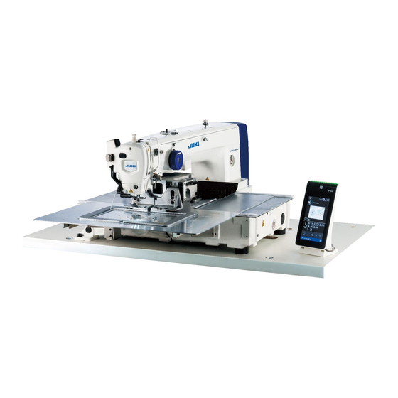
2. CONFIGURATION ❶ ❷ ❸ ❻ ❹ ❼ ❺ ❽ ❾ Air regulator ❶ Machine head ❷ Wiper switch ❸ Temporary stop switch ❹ Feeding frame ❺ Intermediate presser ❻ Thread stand ❼ Operation panel (IP-500) ❽ Power switch (also used as the emergency stop switch) Bird's nest preventing regulator ❾... -
Page 6: Installation
3. INSTALLATION 3-1. Removing the bed fixing bolt Remove bed fixing bolt ❶ . This bolt is necessary to transport the sewing machine. ❶ 3-2. Adjusting the safety switch In the case error 302 occurs when the sewing machine runs after setup, remove screws ❶ (six ❶... -
Page 7: Installing The Throat Plate Auxiliary Cover
3-3. Installing the throat plate auxiliary cover 1. The stay and the like are set to the throat plate auxiliary cover and the fitting screws and washers to the bed are packed together with the accessories at the time of deliv- ery. - Page 8 [When using area 3020 (AMS-221F △△ 3020)] ❷ Move the cloth feed base to the rear, and place throat plate auxiliary cover ❼ (asm.) ❸ from between lower plate ❶ and throat plate ❷ . At this time, be careful not to bend or damage ❶...
-
Page 9: Installing The Panel
3-4. Installing the panel ■ Installing the IP-500 ❹ Open cover ❶ and remove cable ❷ once. As a guide, two perforated holes ❶ (two lo- cations) have been factory-made on the right- ❸ hand side of the table. Pass panel cable ❷ through hole ❺ in the table, and connect the cable to the connector CN101 ❻... -
Page 10: Installing The Thread Stand
In the case of three-pedal unit B ❶ Connect connector ❶ of the pedal to the B side of accessory junction cable ❸ supplied with the unit as described below. Secure ground wire ❷ of the pedal with set- ❸ screw ❺... -
Page 11: Installing The Air Hose
3-7. Installing the air hose Connecting the air hose ❷ Close Connect the air hose to the regulator . Adjustment of air pressure Open Open air cock ❶ , pull up and turn air regula- ❶ tor knob ❷ to adjust the air pressure to 0.5 to 0.55 MPa (for the AMS-221F2516) / 0.35 to 0.4 MPa (for the AMS-221F3020). -
Page 12: Cautions For The Compressed Air Supply (Source Of Supply Air) Facility
When the supply air contains a considerable amount of carbon and dust Mist separator (Most troubles in the air solenoid valves are caused by carbon.) Be sure to install a mist separator. Standard equipment supplied by JUKI Filter regulator Air solenoid valve Air cylinder Cautions for main piping •... -
Page 13: Installing The Eye Protection Cover
3-9. Installing the eye protection cover WARNING : Be sure to attach this cover to protect the eyes from the disperse of needle breakage. Use eye protection cover ❶ after securely attach- ing it on face plate cover ❸ with screw ❷ . If the feeding frame comes in contact ❸... -
Page 14: Preparation Of The Sewing Machine
Turn OFF the power before starting the work so as to prevent accidents caused by abrupt start of the sewing machine. Use [JUKI No. 2 oil] (supplied in the accessory box) for your sewing machine. ❶ Apply one drop of oil to the hook race ❶ part Check that the place between lower line B and upper line A is filled with oil. -
Page 15: Attaching The Needle
4-2. Attaching the needle WARNING : Turn OFF the power before starting the work so as to prevent accidents caused by abrupt start of the sewing machine. Loosen setscrew ❶ and hold needle ❷ with the long groove facing toward you. Then fully insert it into the hole in the needle bar, and tighten setscrew ❶... -
Page 16: Installing And Removing The Bobbin Case
4-4. Installing and removing the bobbin case WARNING : Turn OFF the power before starting the work so as to prevent accidents caused by abrupt start of the sewing machine. Open hook cover ❶ . Raise latch ❸ of bobbin case ❷ , and re- ❸... -
Page 17: Adjusting The Thread Tension
4-6. Adjusting the thread tension If thread tension controller No. 1 ❶ is turned ❶ clockwise, the length of remaining thread on the needle after thread trimming will be shorter. If it is turned counterclockwise, the length will be longer. Longer Shorten the length to an extent that the thread is Shorter... -
Page 18: Intermediate Presser Height
4-7. Intermediate presser height 1. When raising the intermediate presser height, turn the pulley by hand to lower the needle bar, and confirm that the needle bar does not interfere with the intermediate presser. (When using DP X 5 needle, use the sewing machine with the height of 3.5 mm or less.) 2. -
Page 19: Operation Of The Sewing Machine
5. OPERATION OF THE SEWING MACHINE 5-1. Sewing [In case of 2P pedal] 2P pedal 1) Set a workpiece on the sewing machine. 2) Depress the pedal switch A, and the feeding frame will come down. Depress it again, and the feeding frame will go up. -
Page 20: Needle Thread Clamp Device
5-2. Needle thread clamp device Stitch failures (slip-off of the needle thread, stitch skipping and needle-thread stains) are prevented during the high-speed start procedure as well as consistent sewing performance is ensured by operating the needle thread clamp device. The needle thread clamp device can be turned ON/OFF with A. - Page 21 [Regarding H type thread clamp unit] Change the set value of memory switch U069 in accordance with the thickness of needle thread. The set value has been set to 1 : H type thin thread at the time of delivery. Commendable value is Set value : 1 for thread count #50 to #8, Set value : 2 for thread count #20 to #5, and Set value : 3 for thread count #5 to #2.
-
Page 22: Bird's Nest Reducing Device
5-3. Bird’s nest reducing device When the bird’s nest reducing device is used, the needle thread is trimmed at the beginning of sewing. As a result, the needle thread that remains on the reverse side of material is shortened, thereby reduc- ing the formation of so-called bird’s nest (thread tangling) to contribute neater finish of the reverse side of material. -
Page 23: Adjusting The Intermediate Stop Position Of The Feeding Frame (Left) (For The Separately-Driven Feeding Frame With A Double-Stepped Stroke Function)
5-4. Adjusting the intermediate stop position of the feeding frame (left) (For the separately-driven feeding frame with a double-stepped stroke function) WARNING : Turn OFF the power before starting the work so as to prevent accidents caused by abrupt start of the sewing machine. -
Page 24: Operation Section (With Regard To The Panel)
II. OPERATION SECTION (WITH REGARD TO THE PANEL) 1. PREFACE Service patterns are contained in the main body of sewing machine φ60 Pitch 3mm VD00102.VDT 1) Kind of sewing data handled with IP-500 Pattern name Description Users' pattern Pattern that can be stored in the body. Max. - Page 25 4) Folder structure of the media Store each file in the directories below of the media. Media drive VDATA Vector format data VD00 . VDT : Store in ¥VDATA. Store vector format data. VD00 . VDT M3 data : AMS00 .
- Page 26 5) USB port ■ Inserting a device into the USB port Detach the cover from the right side face of the IP- 500. Insert a USB thumb drive into the USB port. Then, copy the data to be used from the IP-500 onto the main body of sewing machine.
- Page 27 • When the storage space of a USB device is partitioned, only one partition is accessible. • Some type of the USB device may not be properly recognized by this sewing machine. • JUKI does not compensate for loss of data stored on the USB device caused by using it with this sewing machine.
-
Page 28: When Using Ip-500
2. WHEN USING IP-500 2-1. Name of each section of IP-500 (Front) (Right side) ⑩ ① ④ ③ ⑤ ⑥ ② ⑦ ⑧ ⑨ ① Touch panel・LCD display section This button is used for changing over the screen between the ②... -
Page 29: Buttons To Be Used In Common
2-2. Buttons to be used in common The buttons which perform common operations in each screen of IP-500 are as follows : This button is used for closing the screen. → CANCEL button In the case this button is pressed when the parameter setting screen is displayed, the data being changed is cancelled. - Page 30 ② Selecting the pattern to be sewn When the power is turned ON, the pattern setting screen is displayed. A is pressed, the When SEWING SHAPE button pattern list screen on which a sewing shape can be selected is displayed. "II-2-4-7.
-
Page 31: Lcd Section During The User Pattern Selection Procedure
2-4. LCD section during the user pattern selection procedure 2-4-1. Pattern setting screen Button and display Description NEW CYCLE PATTERN When this button is pressed, the new cycle pattern creation screen is displayed. → Refer to "II-2-5-3. How to create a new cycle pattern" p.53. -
Page 32: Sewing Screen
2-4-2. Sewing screen Button and display Description SHAPE CONFIRMATION When this button is pressed, the shape confirmation screen is displayed. On this button screen, confirmation of the sewing shape can be carried out. → Refer to "II-2-4-5. How to check the sewing pattern shape" p.36. -
Page 33: Multifunction Tab Display
2-4-3. Multifunction tab display Tab for each function is displayed. The type of tab displayed on the pattern setting screen and that displayed on the sewing screen are different. Select the tab you want to use with the MULTIFUNCTION TAB DISPLAY SELECTION button. Pattern setting Item Sewing screen... -
Page 34: Pattern Shortcut Tab
Pattern shortcut tab It is possible to directly select a pattern without changing over the screen by registering the pattern on the SHORTCUT button. It is also possible to change over the pattern with ease by registering the patterns that you use frequently on the shortcut buttons. On the pattern shortcut tab display, the folders Nos. -
Page 35: Thread Tension Tab
Thread tension tab It is possible to change the reference value of thread tension during sewing. If the reference value of thread tension for a medium pattern is changed, "*" mark will be added to the pattern type display. → Refer to "II-2-4-9. - Page 36 [In case of 2P pedal] 2P pedal Set a workpiece on the sewing machine. Depress the pedal switch A, and the feeding frame will come down. Depress it again, and the feeding frame will go up. Lower the feeding frame. Then press pedal switch B to carry out computation of the en- largement / reduction of the pattern.
-
Page 37: Xy Travel Distance Tab
XY travel distance tab It is possible to move the pattern in parallel. Lower the feeding frame. Lower the feeding frame. Then, set the travel distance by which the pattern is moved with TRAVEL button. Sewing cannot be performed while this tab is selected. Select a different tab in prior in order carry out sewing, 1) Basic operation ①... - Page 38 Parameters that can be changed are as described below. Item Input range Initial value ❶ Two-step stroke 10 to 300(msec) 70(msec) ❷ Thread tension reference value 0 to 200 Set value for pattern ❸ Travel amount in X direction 0.00(mm) ❹...
-
Page 39: How To Check The Sewing Pattern Shape
2-4-5. How to check the sewing pattern shape It is possible to check the needle entry point positions and to check whether the sewing pattern extends outside the feeding frame. 1) Basic operation ① Displaying the sewing screen Display the patturn setting screen. Press READY button A to display the sewing screen on which the sewing machine A is pressed, can start sewing. -
Page 40: How To Correct The Needle Entry Point
2) Selecting the travel method when proceeding stitching Other than the one-stitch forward/backward method, the feeding frame travel method during stitch pro- ceeding can be selected the following ones. The travel method can be changed over in sequence by pressing CHANGEOVER button Travel method Sewing screen One-stitch forward / backward... - Page 41 ③ Editing the thread tension Lower the feeding frame. Proceed stitching. D is pressed, the thread tension When SETTING button increase/decrease value input screen is displayed. Enter a desired value on this screen with numeric keypad E and +/- button G is pressed, the thread tension When ENTER button increase/decrease value command is inserted to the current...
- Page 42 2) How to edit the intermediate presser height ① Displaying the pattern shape confirmation screen A on Press PATTERN SHAPE CONFIRMATION button the sewing screen to display the pattern shape confirmation screen. When INTERMEDIATE PRESER HEIGHT SETTING K is pressed, the intermediate presser is lifted button and lowered.
-
Page 43: How To Select A Sewing Shape
2-4-7. How to select a sewing shape Select the pattern you want to sew. 1) Basic operation ① Displaying the pattern setting screen Only on the pattern setting screen, the sewing shape can be selected. On the sewing screen, press READY button to display the pattern setting screen. - Page 44 2) Selecting a medium pattern ① Inserting the medium Insert the medium into the sewing machine while the pattern setting screen is displayed. B to display the pattern Press SEWING SHAPE button list screen. ② Setting the reference destination to the medium F on the pattern list screen is When SETTING button pressed, the pattern list setting screen is displayed.
- Page 45 4) Narrowing down Only the patterns, from among the saved sewing patterns, that contain the characters entered for their file names or comments can be displayed. ① Displaying the narrow-down screen K is pressed on the When NARROW DOWN button pattern list screen, the narrow-down screen is displayed.
-
Page 46: How To Use Temporary Stop
2-4-8. How to use temporary stop The sewing machine can be stopped by pressing the temporary stop switch during sewing. At this time, the error screen "E050: Temporary stop error" is displayed to inform that the stop ❶ switch has been pressed. (1) To continue performing sewing from some point in sewing ①... -
Page 47: To Perform Re-Sewing From The Start
(2) To perform re-sewing from the start ① Release the error A to release the error. Press RESET button When the error is reset, the thread trimming screen is dis- played. ② Perform thread trimming B to perform thread trim- Press THREAD TRIM button ming. -
Page 48: Winding Bobbin Thread
2-4-10. Winding bobbin thread (1) When performing winding bobbin thread while performing sewing ❶ ❸ ❹ ❷ ❽ ❼ ❺ ❻ Pass the thread in the order of ❶ to ❹ . Insert the thread fully to reach the root of bobbin thread clamp ❺ . Then, trim the thread. (The thread end is retained.) Place a bobbin on bobbin winder shaft ❻... -
Page 49: When Performing Winding Bobbin Thread Only
(2) When performing winding bobbin thread only ① Display the bobbin winding screen A is pressed on the When BOBBIN WINDER button pattern setting screen, the feeding frame comes down. Then, the bobbin winding screen is displayed. ② Start bobbin winding Depress the start pedal, and the sewing machine rotates and starts winding bobbin thread. -
Page 50: How To Edit Characters
2-4-11. How to edit characters Characters used in the file name and comment information of the sewing data stored in the sewing ma- chine can be edited. 1) Basic operation ① Displaying the character edit screen A is When CHARACTER EDIT button pressed on the pattern setting screen, the character edit screen is displayed. -
Page 51: Setting Of The Skip Of Sewing Data
2-4-12. Setting of the skip of sewing data "Sew/not sew" can be set to the pattern consisting of two or more elements that are divided with thread trimming. In the case that two or more materials are used for sewing one piece of pattern data but a part of materials lacks, use this function to sew the lacked material. - Page 52 ④ Confirming the sewing data skip setting E is pressed, the sewing data skip When ENTER button setting is saved. Then, the screen returns to the pattern setting screen or the sewing screen. ⑤ Cancelling the sewing data skip setting F is pressed, the sewing data skip When CLOSE button setting is discarded.
-
Page 53: Lcd Section When Selecting The Cycle Pattern
2-5. LCD section when selecting the cycle pattern This sewing machine is able to combine two or more pattern data and sew them in sequence. As many as 30 patterns can be registered in one cycle pattern. Use this function when you want to sew several different sewing shapes on a sewn product. - Page 54 Button and display Description BOBBIN WINDER button When this button is pressed, the bobbin winding screen is displayed. On this screen, winding of a bobbin can be carried out. → Refer to "II-2-4-10. Winding bobbin thread" p.45. SEWING SHAPE The selected pattern type is displayed on the button. SELECTION button : Users' pattern : Media pattern...
-
Page 55: Sewing Screen
2-5-2. Sewing screen Button and display Description SHAPE CONFIRMATION When this button is pressed, the shape confirmation screen is displayed. On this button screen, confirmation of the sewing shape can be carried out. → Refer to "II-2-4-5. How to check the sewing pattern shape" p.36. -
Page 56: How To Create A New Cycle Pattern
Button and display Description FEEDING FRAME INITIAL When this button is pressed while the sewing machine temporarily stops sewing, the POSITION button feeding frame is returned to the start of sewing and is lifted. CURRENT STEP Step to be sewn can be proceeded to the next one with this button. CHANGEOVER button (+) CURRENT STEP Step to be sewn can be returned to the previous one with this button. - Page 57 ② Creating a new file Enter the file name of a new cycle pattern you want to create. → Refer to "II-2-4-11. How to edit characters" p.47. B is pressed, the cycle pattern set- When ENTER button ting screen is displayed. ③...
-
Page 58: How To Edit Steps Of The Cycle Pattern
2-5-4. How to edit steps of the cycle pattern Insertion / changeover / deletion of the registered steps of a cycle pattern can be carried out. 1) Basic operation ① Displaying the cycle step edit screen A is pressed on the cycle pat- When STEP EDIT button tern setting screen, the cycle step edit screen is displayed. - Page 59 2) Inserting a step A step is inserted into the position immediately before the pat- tern that is currently selected with PATTEN SELECTION button ① Selecting a pattern into which a step is inserted D is pressed on the step When STEP INSETION button edit screen, the pattern selection screen is displayed.
-
Page 60: How To Set Skipping Of A Cycle Step(S)
2-5-5. How to set skipping of a cycle step(s) It is possible to set to skip a desired step(s). Use this function in the case there is a step(s) that you want to temporarily skip without changing the registered step information for the cycle pattern. ①... -
Page 61: How To Sew One Step In Repletion
2-5-6. How to sew one step in repletion It is possible to sew a desired step registered in a cycle pattern in repetition. Use this function in the case there is a step(s) that you want to temporarily skip without changing the registered step information for the cycle pattern. -
Page 62: Changing Over The Input Mode Between The Normal Mode And The Main-Body Input Mode
Table display list The below-stated items are shown on the list screen. Name of item Overview Mode changeover This item is used for changing over the input mode between the normal (Normal ⇔ Main-body input) mode and the main-body input mode Memory switch This item is used for setting the memory switch data. -
Page 63: Memory Switch
2-6-2. Memory switch Memory switch data are the motion data that the sewing machine has in common and the data that op- erate on all sewing patterns in common. (1) How to change the memory switch data Setting Setting Setting Unit &... - Page 64 Setting Setting Setting Unit & Name Selection item range rage range Meaning Thread tension for the 3th stitch at the U024 beginning of sewing (With the thread clamp) 2-step stroke position of the mo- U026 tor-controlled feeding frame 0: Standard (linear) U030 Setting of the thread tension output 1: Low-tension detailed setting 2: Hight-tension detailed setting...
- Page 65 Setting Setting Setting Unit & Name Selection item range rage range Meaning Selection of enable / disable of wiper 0: Disable U051 output 1: Enable Method to set the XY enlargement / 0: Set in % U064 reduction ratio 1: Set with actual dimension Thread tension output time during U068 1 stitch...
- Page 66 Setting Setting Setting Unit & Name Selection item range rage range Meaning 0: 2800sti/min /3.5mm Main motor XY feed synchronous 1: 2200sti/min /3.5mm U101 control speed / pitch 2: 1800sti/min /3.5mm 3: 1300sti/min /3.5mm 0: Without (Fixed to lowering) 1: With (Lowering according to the With / without the intermediate presser U103 sewing data during operation)
- Page 67 Setting Setting Setting Unit & Name Selection item range rage range Meaning Possible lowering height of the needle U330 bar (degree of an angle from the lower 1° dead point) 0: Pattern numbers and file names U400 Management of file names of patterns 1: Only the pattern numbers U402 Automatic lock time Period of time to be elapsed before...
-
Page 68: Setting The Counter
2-6-3. Setting the counter 1) Basic operation ① Setting the counter When COUNTER SETTING button A is pressed on the list screen, the counter setting screen is displayed. ② Selecting the type of counter When COUNTER TYPE SELEC- TION button B is pressed, the counter type selection screen is displayed. - Page 69 ④ Setting the current value of counter F is When CURRENT VALUE SETTING button pressed, the counter current value input screen is displayed. Enter the current value with numeric keypad J. Then, press ENTER button + / - button to confirm. 2) "Count complete"...
-
Page 70: Setting The Clock
3) Counter current-value changing procedure during sew- When the COUNTER CURRENT-VALUE button which is displayed on the pattern setting screen or on the HOME tab of sewing screen, is pressed, the current value of counter can be changed. → Refer to "II-2-4-4. -
Page 71: Registering The Pattern Shortcut Key
2-6-5. Registering the pattern shortcut key Pattern that is saved in the sewing machine can be registered to PATTERN SHORTCUT key. The registered patterns are displayed on the pattern setting screen or on the pattern shortcut tab of sewing screen to allow selection of the pattern. Vector data and cycle pattern data can be registered to PATTERN SHORTCUT key. -
Page 72: Using Communication Function
It is the data of needle entry point created with Vector data PM-1, and the data format that can be operated ××××××.VDT in common between JUKI sewing machines. M3 data ××××××.M3 Pattern data for the AMS-B, -C and -D Series Standard format for sewing ××××××.DAT... -
Page 73: Performing Communication By Using Usb
2-7-3. Performing communication by using USB Data can be sent/received to/from a personal computer or the like, by means of a USB cable. If the contact part becomes dirty, failure of contact will be caused. Do not touch by hand, and control so that dust, oil or other foreign material does not adhere to it. - Page 74 ⑤ Determining the destination file name The destination file name on the communication screen displays the file name that is same as the name of file to be written. If you do not want to change the file name, proceed to ⑥...
-
Page 75: Taking In Plural Data Together
2-7-5. Taking in plural data together For the vector data, M3 data, sewing standard format data and cycle pattern data, two or more pieces of data can be selected at a time and written collectively. The write destination file name becomes the same one as the selected file. ①... -
Page 76: Error Code List
3. ERROR CODE LIST Error Place of Description of error Display message How to recover code recovery Machine lock E007 Turn OFF the Main shaft of the sewing machine power fails to rotate due to some trouble E008 Head connector abnormality Turn OFF the Memory of machine head cannot power... - Page 77 Error Place of Description of error Display message How to recover code recovery Pattern data size over E024 Possible to re- Data input Memory size is over. start after reset. screen E030 Needle bar position missing Turn hand Data input error pulley to bring screen...
- Page 78 Error Place of Description of error Display message How to recover code recovery Grease-up warning E220 Possible to re- Data input At the time of operation of 100 start after reset. screen million stitches → Refer to “III-1-10. Replenishing the designated places with grease”...
- Page 79 Error Place of Description of error Display message How to recover code recovery Overvoltage E811 Turn OFF the When input power is more than power the specified value. E813 Low voltage Turn OFF the When input power is less than the power specified value.
- Page 80 Error Place of Description of error Display message How to recover code recovery Y motor position slip error E927 1. In case of error 1. Step display during screen sewing Possible to re- start after reset 2. In case of error 2.
-
Page 81: Message List
4. MESSAGE LIST Message No. Display message Description M520 Erase confirmation of Users' pattern Erase is performed. OK ? M522 Erase confirmation cycle pattern Erase is performed. OK ? M523 Erase confirmation of backup data Pattern data is not stored in memory. Erase is OK ? M528 Overwriting confirmation of users' pattern Overwriting is performed. - Page 82 Message No. Display message Description Deletion confirmation of intermediate presser M538 increase/decrease value Deleting is performed. OK ? M542 Format confirmation Formatting is performed. OK ? M544 Data corresponding to panel does not exist. Data does not exist. Data corresponding to media does not exist. M545 Data does not exist.
- Page 83 Message No. Display message Description Confirmation of clearance of password setting M557 Clears password Yes or no M653 During formatting Formatting is performed. M669 During data reading Data is being read. During data writing M670 Data is being written. M671 During data converting Data is being converted.
-
Page 84: Maintenance Of Sawing Machine
III. MAINTENANCE OF SAWING MACHINE 1. MAINTENANCE 1-1. Adjusting the height of the needle bar (Changing the length of the needle) WARNING : Turn OFF the power before starting the work so as to prevent accidents caused by abrupt start of the sewing machine. - Page 85 Loosen setscrew ❶ in the driver. Drawing ❹ ❸ bobbin case opening lever hook ❷ toward you, open it to the right and left until bobbin case opening lever ❸ comes off. At this time, be careful not to let ❷...
- Page 86 [Adjustment of height of driver] Adjust so that the blade point of inner hook ❹ meets the center of needle ❺ and tighten setscrew ❶ . Bend the needle guard section of driver ❻ in the direction of arrow A so that the protruding amount from the bottom end of the needle guard section of driver ❻...
-
Page 87: Adjusting The Height Of The Feeding Frame
1-3. Adjusting the height of the feeding frame WARNING : Turn OFF the power before starting the work so as to prevent accidents caused by abrupt start of the sewing machine. Loosen setscrews ❷ located on the right and left sides of feed bracket ❶ . Moving cloth presser link ❸... -
Page 88: Adjusting The Vertical Stroke Of The Intermediate Presser
1-4. Adjusting the vertical stroke of the intermediate presser WARNING : Turn OFF the power before starting the work so as to prevent accidents caused by abrupt start of the sewing machine. * Turn ON the power once, and turn OFF the power again after making the intermediate presser in the lowered state. - Page 89 Dimension A (mm) varies with the sewing specification (diameter of the needle hole guide). Adjust dimension A referring to the table shown below. Sewing specification Type S Type H Type G Diameter of needle hole φ1.6 φ2.0 / 2.4 φ3.0 guide 40196074 Part number of needle hole...
- Page 90 C four times to put E in Press ROTATE button the selected state. At this time, adjust the clearance provided between the count- er knife and the moving knife to 1.1 mm. Adjust the clearance G until the clearance becomes the with +/- key specified adjustment value.
-
Page 91: The Moving Knife And Counter Knife (Shorter-Thread Remaining Type)
1-6. The moving knife and counter knife (Shorter-thread remaining type) WARNING : Turn OFF the power before starting the work so as to prevent accidents caused by abrupt start of the sewing machine. Length of thread remaining on the material at the end of sewing can be reduced. For synthetic filament thread #20, the length of thread remaining on the material at the end of sewing is reduced by approximately 1 mm. -
Page 92: Needle Thread Clamp Device
1-7. Needle thread clamp device WARNING : Turn OFF the power before starting the work so as to prevent accidents caused by abrupt start of the sewing machine. ❶ ❸ ❷ ❸ ❷ When thread is caught at top end ❶ of the thread clamp, thread clamp becomes incomplete and sewing trouble at the sewing start will be caused. -
Page 93: Raising The Machine Head
1-9. Raising the machine head WARNING : Tilt/raise the sewing machine head with both hands taking care not to allow your fingers to be caught in the head. Turn OFF the power before starting the work so as to prevent accidents caused by abrupt start of the sewing machine. - Page 94 To return the sewing machine to its initial position, follow the steps of procedure described below. Return stopper release lever ❻ to its initial position. (Return the lever until it is fixed.) Carefully return machine head grip ❶ to its ❻...
-
Page 95: Replenishing The Designated Places With Grease
1-10. Replenishing the designated places with grease * Perform grease supplement when the errors below are displayed or once a year (either one which is earlier). If grease has decreased due to cleaning of the sewing machine or any other reasons, be sure to immediately add grease. -
Page 96: Location Where Exclusive Grease Is Provided
(1) Location where exclusive grease is provided Two types of grease, i.e., JUKI GREASE A ❶ and GREASE B ❷ , the grease nipple specifically de- signed for JUKI GREASE B and grease ❸ specifically developed for the linear guide are contained in the accessory box. - Page 97 Remove setscrew ❽ from the intermediate ❻ presser bar bushing grease hole. Put JUKI Grease A through inlet ❾ . Tighten screw ❽ to fill inside the bushing with JUKI Grease A. ❼ ❷ Do not wipe off the grease applied onto the periphery of needle bar inside the frame.
- Page 98 ■ Grease supplement to the face plate section Open the face plate cover. ❹ ❸ Add the JUKI Grease A onto the felt sections (3 locations), peripheral shoulder screw, ful- crums ❶ to ❼ and guide groove section ❽ . ❶...
-
Page 99: Portions To Which The Linear-Guide Specific Grease Is Applied
(3) Portions to which the linear-guide specific grease is applied To add grease to the points specified below, use the accessory grease (part number: 40097886) supplied with the unit. If any grease other than the specified one is used, the related components can be damaged. -
Page 100: Draining Waste Oil
1-11. Draining waste oil When polyethylene oiler ❶ becomes filled with oil, remove polyethylene oiler ❶ and drain the oil. ❶ 1-12. Amount of oil supplied to the hook Loosen setscrew ❶ and remove setscrew ❶ . ❹ When screwing in adjustment screw ❷ , the amount of oil of oil pipe, left ❹... -
Page 101: Replacing The Fuse
1-13. Replacing the fuse DANGER : 1. To avoid electrical shock hazards, turn OFF the power and open the control box cover after about five minutes have passed. 2. Open the control box cover after turning OFF the power without fail. Then, replace with a new fuse with the specified capacity. -
Page 102: Changing Over The Supply Voltage
1-14. Changing over the supply voltage DANGER : 1. To avoid electrical shock hazards, turn OFF the power and open the control box cover after about five minutes have passed. 2. Open the control box cover after turning OFF the power without fail. Then, changing over the supply voltage. -
Page 103: Disposal Of Batteries
1-15. Disposal of batteries The operation panel incorporates batteries for operating the clock while the power is turned OFF. Dispose of the batteries appropriately according to the relevant local laws and regulations in your country / region. ■ How to remove batteries Detach operation panel ❶... -
Page 104: Troubles And Corrective Measures (Sewing Conditions)
1-16. Troubles and corrective measures (Sewing conditions) Trouble Cause Corrective measures Page ① Stitches are slipped at the start. 1. The needle ○ Adjust the clearance between the needle and the shuttle to 0.05 to 0.1 mm. thread slips off at the start of bar- ○... - Page 105 Trouble Cause Corrective measures Page ① The needle is bent. 3. The needle often ○ Replace the bent needle. breaks. ② The needle strikes the intermediate ○ Correct the position of the intermediate presser foot. presser foot. ③ The needle is too thin for the ○...
- Page 106 Trouble Cause Corrective measures Page ① The needle thread at the sewing 9. The thread clamp ○ Tighten thread tension controller No. 1 is entangled with start is too long. and make the length of needle thread 40 needle thread. to 50 mm.
-
Page 107: Optional
2. OPTIONAL 2-1. Table of Needle hole guide Needle used Needle hole guide Size Part No. Needle hole diameter Application #09 to #11 40207153 ø 1.6 For knits (OP) #11 to #14 *1 40196061 ø 1.6 For light-weight to medium-weight materials (S type) For medium-weight to heavy-weight materials (H #14 to #18 *2 40196067... -
Page 108: To Use The Feed Plate Of The Ams-221En Series
Place an order for the interchangeable plate set of the following part number. It should be noted that the feeing frame of the AMS-221EN Series can be used with the AMS-221F as it JUKI interchangeable plate set part No. For AMS-221F △△ 3020 40218950 For AMS-221F △△...
Need help?
Do you have a question about the AMS-221F-2516 and is the answer not in the manual?
Questions and answers