Table of Contents
Advertisement
Quick Links
Sherwood Industries
Ltd.
Project # 21-694
Model: Enviro Mini 2
AKA:
Enviro P3-2
Regency Greenfire GF40-2
Type: Pellet-Fired Freestanding Heater
May 28, 2021
Revised: June 30, 2021
ASTM E2779 Standard Test Method for
Determining Particulate Matter Emissions
from Pellet Heaters
Contact: Garrett Posehn
Sherwood Industries Ltd.
6782 Oldfield Rd.
Victoria, BC Canada
V8M 2A3
250-652-6080
Prepared by: Aaron Kravitz
11785 SE Highway 212 – Suite 305
Clackamas, OR 97015-9050
(503) 650-0088
WWW.PFSTECO.COM
Advertisement
Chapters
Table of Contents
Troubleshooting

Related Manuals for Enviro Mini 2


Summary of Contents for Enviro Mini 2
- Page 1 Sherwood Industries Ltd. Project # 21-694 Model: Enviro Mini 2 AKA: Enviro P3-2 Regency Greenfire GF40-2 Type: Pellet-Fired Freestanding Heater May 28, 2021 Revised: June 30, 2021 ASTM E2779 Standard Test Method for Determining Particulate Matter Emissions from Pellet Heaters Contact: Garrett Posehn Sherwood Industries Ltd.
- Page 2 Project # 21-694 Model: Mini 2 Revision Summary Date: May 28, 2021 – Original Issue Date: June 30, 2021 – The following revisions were made per request from the EPA: -A section was added to the “Settings & Run Notes” table to clarify air damper position for testing, see page 9 of test report.
-
Page 3: Table Of Contents
Project # 21-694 Model: Mini 2 Contents Affidavit ..................................3 Introduction ................................... 4 Notes ..................................4 Pellet Heater Identification and Testing ........................5 Test Procedures and Equipment ........................... 6 Results ................................... 7 Summary Table................................7 Test Run Narrative..............................7 Run 1 ..................................7 Test Conditions Summary .............................. -
Page 4: Affidavit
Affidavit PFS-TECO was contracted by Sherwood Industries Ltd. to provide testing services for the Enviro Mini 2 Pellet-Fired Fireplace Insert per ASTM E2779, Determining PM Emissions from Pellet Heaters. All testing and associated procedures were conducted at PFS-TECO’s Portland Laboratory on 4/14/2021. PFS-TECO’s Portland Laboratory is located at 11785 SE Highway 212 –... -
Page 5: Introduction
Model: Mini 2 Introduction Sherwood Industries Ltd. of Victoria, BC contracted with PFS-TECO to perform EPA certification testing on the Enviro Mini 2 Pellet-Fired Room Heater. All testing was performed at PFS-TECO’s Portland Laboratory. Testing was performed by Mr. Aaron Kravitz. -
Page 6: Pellet Heater Identification And Testing
Project # 21-694 Model: Mini 2 Pellet Heater Identification and Testing • Appliance Tested: Enviro Mini 2 • Serial Number: N/A – Prototype Unit; PFS Tracking Number 0094 • Manufacturer: Sherwood Industries Ltd. • Catalyst: No • Heat exchange blower: Integral •... -
Page 7: Test Procedures And Equipment
Project # 21-694 Model: Mini 2 Test Procedures and Equipment All Sampling and analytical procedures were performed by Aaron Kravitz. All procedures used are directly from ASTM E2779 and ASTM E2515. See the list below for equipment used. See Appendix C submitted with this report for calibration data. -
Page 8: Results
Higher Heating Values efficiency of 80.2% and a CO emission rate of 0.03 g/min. The calculated first hour particulate emission rate was 1.26 g/hr. The Sherwood Industries Ltd. Model Enviro Mini 2 Pellet-Fired Room Heater meets the 2020 PM emission standard of ≤ 2.0 g/hr per CFR 40 part 60, §60.532 (b). -
Page 9: Appliance Operation And Test Settings
Project # 21-694 Model: Mini 2 Appliance Operation and Test Settings The appliance was operated according to procedures as described in the Operations Manual, found in Appendix B submitted with this report. Detailed run information can be found in Appendix A submitted with this report. -
Page 10: Appliance Description
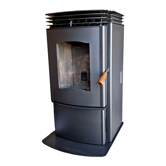
Model(s): Enviro Mini 2 Additional Models Discussion: The Mini-2 is available in several other model designations, but these models (the Enviro P3-2 and Regency Greenfire GF40-2) are marketing designations only and are in all respects that may affect emissions performance identical to the tested unit. - Page 11 Project # 21-694 Model: Mini 2 Appliance Front Appliance Left Page | 10...
- Page 12 Project # 21-694 Model: Mini 2 Appliance Right Appliance Rear Page | 11...
-
Page 13: Test Fuel Properties
Project # 21-694 Model: Mini 2 Test Fuel Properties Test fuel used was Lignetics Wood Pellet Fuel, a PFI Certified Premium Pellet Brand. A sample of pellets was sent to Twin Ports Testing for analysis, see report below. Page | 12... -
Page 14: Pellet Fuel Analysis
Project # 21-694 Model: Mini 2 Pellet Fuel Analysis Page | 13... -
Page 15: Sampling Locations And Descriptions
Project # 21-694 Model: Mini 2 Sampling Locations and Descriptions Sample ports are located 16.5 feet downstream from any disturbances and 1 foot upstream from any disturbances. Flow rate traverse data was collected 12 feet downstream from any disturbances and 5.5 feet upstream from any disturbances. (See below). -
Page 16: Sampling Methods
Project # 21-694 Model: Mini 2 Sampling Methods ASTM E2515 was used in collecting particulate samples. The dilution tunnel is 6 inches in diameter. All sampling conditions per ASTM E2515 were followed. No alternate procedures were used. Analytical Methods Description All sample recovery and analysis procedures followed ASTM E2515 procedures. -
Page 17: Sealed Unit
Project # 21-694 Model: Mini 2 Sealed Unit Page | 16... -
Page 18: List Of Appendices
Project # 21-694 Model: Mini 2 List of Appendices The following appendices have been submitted electronically in conjunction with this report: Appendix A – Test Run Data, Technician Notes, and Sample Analysis Appendix B – Labels and Manuals Appendix C – Equipment Calibration Records Appendix D –... - Page 19 Conditioning Burn Data Date(s):3/23/21 - 3/26/21 Flue 8' Scale (lb) Loss (lb) Time (hr) 174.23 81.4 184.45 79.5 182.80 77.4 183.73 75.3 183.39 73.2 196.19 71.0 195.50 69.0 193.22 67.0 198.75 64.9 200.55 62.7 198.93 60.7 196.94 58.6 199.67 56.4 200.17 54.3 201.34...
- Page 20 180.40 69.8 178.31 67.7 180.07 65.5 180.10 63.3 181.74 61.2...
- Page 21 Mini Test Recommendations Set-Up The unit should be set up with a 6in flue and the air dampener in the rear of the unit set to a position that after running on a setting of 5 heat, 5 Feed Trim and 5 Combustion Trim the Vacuum of the fire box should be .06 in H2O, the CO2 should be around 7.% in the exhaust and an 8’...
- Page 22 PELLET TEST DATA PACKET ASTM E2779/E2515 Run 1 Data Summary Client: Sherwood Model: Mini 2 Job #: 21-694 Tracking #: Test Date: 4/14/2021 5/28/2021 Techician Signature Date PFS-TECO...
- Page 23 Run 1 Emissions.xlsm TEST RESULTS - ASTM E2779 / ASTM E2515 Client: Sherwood Job #: 21-694 Model: Mini 2 Tracking #: Run #: Technician: Date: 4/14/2021 Burn Rate Summary High Burn Rate (dry kg/hr) 1.54 Medium Burn Rate (dry kg/hr) 0.69...
- Page 24 Run 1 Emissions.xlsm Overall Pellet Test Efficiency Results Manufacturer: Sherwood Model: Mini 2 Date: 04/14/21 Run: 1 Control #: 21-694 Test Duration: 360 Output Category: Integrated Test Results in Accordance with CSA B415.1-09 HHV Basis LHV Basis Overall Efficiency 80.152% 87.4%...
- Page 25 Run 1 Emissions.xlsm Max Burn Rate Segment Efficiency Results Manufacturer: Sherwood Model: Mini 2 Date: 04/14/21 Run: 1 Control #: 21-694 Test Duration: 60 Output Category: Maximum Test Results in Accordance with CSA B415.1-09 HHV Basis LHV Basis Overall Efficiency 81.0%...
- Page 26 Run 1 Emissions.xlsm Medium Burn Rate Segment Efficiency Results Manufacturer: Sherwood Model: Mini 2 Date: 04/14/21 Run: 1 Control #: 21-694 Test Duration: 120 Output Category: Medium Test Results in Accordance with CSA B415.1-09 HHV Basis LHV Basis Overall Efficiency 75.6%...
- Page 27 Run 1 Emissions.xlsm Minimum Burn Rate Segment Efficiency Results Manufacturer: Sherwood Model: Mini 2 Date: 04/14/21 Run: 1 Control #: 21-694 Test Duration: 180 Output Category: Minimum Test Results in Accordance with CSA B415.1-09 HHV Basis LHV Basis Overall Efficiency 83.1%...
- Page 28 Run 1 Emissions.xlsm DILUTION TUNNEL & MISC. DATA - ASTM E2779 / E2515 Client: Sherwood Job #: 21-694 Model: Mini 2 Tracking #: Run #: Technician: Test Start Time: 9:05 Date: 4/14/2021 High Burn End Time (min): Medium Burn End Time (min):...
- Page 29 Run 1 Emissions.xlsm PELLET STOVE PREBURN DATA - ASTM E2779 Client: Sherwood Job #: 21-694 Model: Mini 2 Tracking #: 91 Run #: Technician: Date: 4/14/2021 Recording Interval (min): Run Time (min): Average: -0.033 Flue Draft (in Elapsed Time Scale Weight Change Flue (°F)
- Page 30 Run 1 Emissions.xlsm PELLET STOVE PREBURN DATA - ASTM E2779 Client: Sherwood Job #: 21-694 Model: Mini 2 Tracking #: 91 Run #: Technician: Date: 4/14/2021 38.7 -0.1 -0.040 38.7 -0.040 38.6 -0.1 -0.040 38.5 -0.11 -0.040 38.5 0.01 -0.040 38.4...
- Page 31 Run 1 Emissions.xlsm BOX A TEST DATA - ASTM E2779 / ASTM E2515 Client: Sherwood Job #: 21-694 Model: Mini 2 Tracking #: 91 Run #: 1 Technician: AK Date: 4/14/2021 Fuel Weight (lb) Temperature Data (°F) Particulate Sampling Data...
- Page 32 Run 1 Emissions.xlsm BOX A TEST DATA - ASTM E2779 / ASTM E2515 Client: Sherwood Job #: 21-694 Model: Mini 2 Tracking #: 91 Run #: 1 Technician: AK Date: 4/14/2021 Fuel Weight (lb) Temperature Data (°F) Particulate Sampling Data...
- Page 33 Run 1 Emissions.xlsm BOX A TEST DATA - ASTM E2779 / ASTM E2515 Client: Sherwood Job #: 21-694 Model: Mini 2 Tracking #: 91 Run #: 1 Technician: AK Date: 4/14/2021 Fuel Weight (lb) Temperature Data (°F) Particulate Sampling Data...
- Page 34 Run 1 Emissions.xlsm BOX A TEST DATA - ASTM E2779 / ASTM E2515 Client: Sherwood Job #: 21-694 Model: Mini 2 Tracking #: 91 Run #: 1 Technician: AK Date: 4/14/2021 Fuel Weight (lb) Temperature Data (°F) Particulate Sampling Data...
- Page 35 Run 1 Emissions.xlsm BOX A TEST DATA - ASTM E2779 / ASTM E2515 Client: Sherwood Job #: 21-694 Model: Mini 2 Tracking #: 91 Run #: 1 Technician: AK Date: 4/14/2021 Fuel Weight (lb) Temperature Data (°F) Particulate Sampling Data...
- Page 36 Run 1 Emissions.xlsm BOX A TEST DATA - ASTM E2779 / ASTM E2515 Client: Sherwood Job #: 21-694 Model: Mini 2 Tracking #: 91 Run #: 1 Technician: AK Date: 4/14/2021 Fuel Weight (lb) Temperature Data (°F) Particulate Sampling Data...
- Page 37 Run 1 Emissions.xlsm BOX A TEST DATA - ASTM E2779 / ASTM E2515 Client: Sherwood Job #: 21-694 Model: Mini 2 Tracking #: 91 Run #: 1 Technician: AK Date: 4/14/2021 Fuel Weight (lb) Temperature Data (°F) Particulate Sampling Data...
- Page 38 Run 1 Emissions.xlsm BOX A TEST DATA - ASTM E2779 / ASTM E2515 Client: Sherwood Job #: 21-694 Model: Mini 2 Tracking #: 91 Run #: 1 Technician: AK Date: 4/14/2021 Fuel Weight (lb) Temperature Data (°F) Particulate Sampling Data...
- Page 39 Run 1 Emissions.xlsm BOX A TEST DATA - ASTM E2779 / ASTM E2515 Client: Sherwood Job #: 21-694 Model: Mini 2 Tracking #: 91 Run #: 1 Technician: AK Date: 4/14/2021 Fuel Weight (lb) Temperature Data (°F) Particulate Sampling Data...
- Page 40 Run 1 Emissions.xlsm BOX A TEST DATA - ASTM E2779 / ASTM E2515 Client: Sherwood Job #: 21-694 Model: Mini 2 Tracking #: 91 Run #: 1 Technician: AK Date: 4/14/2021 Fuel Weight (lb) Temperature Data (°F) Particulate Sampling Data...
- Page 41 Run 1 Emissions.xlsm BOX A TEST DATA - ASTM E2779 / ASTM E2515 Client: Sherwood Job #: 21-694 Model: Mini 2 Tracking #: 91 Run #: 1 Technician: AK Date: 4/14/2021 Fuel Weight (lb) Temperature Data (°F) Particulate Sampling Data...
- Page 42 Run 1 Emissions.xlsm BOX A TEST DATA - ASTM E2779 / ASTM E2515 Client: Sherwood Job #: 21-694 Model: Mini 2 Tracking #: 91 Run #: 1 Technician: AK Date: 4/14/2021 Fuel Weight (lb) Temperature Data (°F) Particulate Sampling Data...
- Page 43 Run 1 Emissions.xlsm BOX B TEST DATA - ASTM E2779 / ASTM E2515 Client: Sherwood Job #: 21-694 Model: Mini 2 Tracking #: Run #: Technician: Date: 4/14/2021 Particulate Sampling Data Flue Gas Data Meter Gas Meter Orifice dH Flue Draft...
- Page 44 Run 1 Emissions.xlsm BOX B TEST DATA - ASTM E2779 / ASTM E2515 Client: Sherwood Job #: 21-694 Model: Mini 2 Tracking #: Run #: Technician: Date: 4/14/2021 Particulate Sampling Data Flue Gas Data Meter Gas Meter Orifice dH Flue Draft...
- Page 45 Run 1 Emissions.xlsm BOX B TEST DATA - ASTM E2779 / ASTM E2515 Client: Sherwood Job #: 21-694 Model: Mini 2 Tracking #: Run #: Technician: Date: 4/14/2021 Particulate Sampling Data Flue Gas Data Meter Gas Meter Orifice dH Flue Draft...
- Page 46 Run 1 Emissions.xlsm BOX B TEST DATA - ASTM E2779 / ASTM E2515 Client: Sherwood Job #: 21-694 Model: Mini 2 Tracking #: Run #: Technician: Date: 4/14/2021 Particulate Sampling Data Flue Gas Data Meter Gas Meter Orifice dH Flue Draft...
- Page 47 Run 1 Emissions.xlsm BOX B TEST DATA - ASTM E2779 / ASTM E2515 Client: Sherwood Job #: 21-694 Model: Mini 2 Tracking #: Run #: Technician: Date: 4/14/2021 Particulate Sampling Data Flue Gas Data Meter Gas Meter Orifice dH Flue Draft...
- Page 48 Run 1 Emissions.xlsm BOX B TEST DATA - ASTM E2779 / ASTM E2515 Client: Sherwood Job #: 21-694 Model: Mini 2 Tracking #: Run #: Technician: Date: 4/14/2021 Particulate Sampling Data Flue Gas Data Meter Gas Meter Orifice dH Flue Draft...
- Page 49 Run 1 Emissions.xlsm BOX B TEST DATA - ASTM E2779 / ASTM E2515 Client: Sherwood Job #: 21-694 Model: Mini 2 Tracking #: Run #: Technician: Date: 4/14/2021 Particulate Sampling Data Flue Gas Data Meter Gas Meter Orifice dH Flue Draft...
- Page 50 Run 1 Emissions.xlsm BOX B TEST DATA - ASTM E2779 / ASTM E2515 Client: Sherwood Job #: 21-694 Model: Mini 2 Tracking #: Run #: Technician: Date: 4/14/2021 Particulate Sampling Data Flue Gas Data Meter Gas Meter Orifice dH Flue Draft...
- Page 51 Run 1 Emissions.xlsm BOX B TEST DATA - ASTM E2779 / ASTM E2515 Client: Sherwood Job #: 21-694 Model: Mini 2 Tracking #: Run #: Technician: Date: 4/14/2021 Particulate Sampling Data Flue Gas Data Meter Gas Meter Orifice dH Flue Draft...
- Page 52 Run 1 Emissions.xlsm BOX B TEST DATA - ASTM E2779 / ASTM E2515 Client: Sherwood Job #: 21-694 Model: Mini 2 Tracking #: Run #: Technician: Date: 4/14/2021 Particulate Sampling Data Flue Gas Data Meter Gas Meter Orifice dH Flue Draft...
- Page 53 Run 1 Emissions.xlsm BOX B TEST DATA - ASTM E2779 / ASTM E2515 Client: Sherwood Job #: 21-694 Model: Mini 2 Tracking #: Run #: Technician: Date: 4/14/2021 Particulate Sampling Data Flue Gas Data Meter Gas Meter Orifice dH Flue Draft...
- Page 54 Run 1 Emissions.xlsm BOX B TEST DATA - ASTM E2779 / ASTM E2515 Client: Sherwood Job #: 21-694 Model: Mini 2 Tracking #: Run #: Technician: Date: 4/14/2021 Particulate Sampling Data Flue Gas Data Meter Gas Meter Orifice dH Flue Draft...
- Page 55 Run 1 Emissions.xlsm LAB SAMPLE DATA - ASTM E2515 Client: Sherwood Job #: 21-694 Model: Mini 2 Tracking #: 91 Run #: Technician: AK Date: 4/14/2021 Sample ID Tare, mg Total, mg Final, mg Catch, mg Train A Filters - G0027 121.9...
- Page 56 Form P405 ASTM E2779 Run Notes Client: Sherwood Appliance: Mini 2 Project: 21-694 Pellet Heater Control Settings High Burn Rate Settings: 5 Heat, 5 Feed Trim, 2 Combustion Trim Medium Burn Rate Settings: 2 Heat, 1 Feed Trim, 1 Combustion Trim...
- Page 60 Equations and Sample Calculations – ASTM E2779 & E2515 Client Sherwood Model: Mini 2 Tracking #: Run: Equations used to calculate the parameters listed below are described in this appendix. Sample calculations are provided for each equation. The raw data and printout results from a sample run are also provided for comparison to the sample calculations.
- Page 61 Run 1 Emissions.xlsm – Weight of test fuel burned during test run, dry basis, kg ASTM E2779 equation (1) = (M )(100/(100 + FM)) Where, average fuel moisture of test fuel, % dry basis weight of test fuel in hopper at start of test run, wet basis, kg weight of test fuel in hopper at end of test run, wet basis, kg Sample Calculation: FM = 5.14 %...
- Page 62 Run 1 Emissions.xlsm – Weight of test fuel burned during test run segment i , dry basis, kg BSidb ASTM E2779 equation (2) = (MS )(100/(100 + FM)) BSidb Siwb ESiwb Where, weight of test fuel in hopper at start of test run segment i , wet basis, kg SSiwb weight of test fuel in hopper at end of test run segment i , wet basis, kg ESiwb...
- Page 63 Run 1 Emissions.xlsm BR – Average dry burn rate over full integrated test run, kg/hr ASTM E2779 equation (3) 60 M θ Where, θ = Total length of full integrated test run, min Sample Calculation: = 4.21 θ = 360 60 x 4.21 0.70 kg/hr...
- Page 64 Run 1 Emissions.xlsm – Average dry burn rate over test run segment i , kg/hr ASTM E2779 equation (4) 60 M BSidb θ Where, Total length of test run segment i , min θ Sample Calculation (from medium burn rate segment): 1.38 BSidb θ...
- Page 65 Run 1 Emissions.xlsm – Average gas velocity in the dilution tunnel, ft/sec ASTM E2515 equations (9) Where: Adjustment factor for center of tunnel pitot tube strav , ASTM E2515 Equation (1) placement, Fp = scent Dilution tunnel velocity calculated after the multi-point pitot traverse at the center, ft/sec scent...
- Page 66 Run 1 Emissions.xlsm – Average gas flow rate in dilution tunnel, dscf/hr ASTM E2515 equation (3) − 3600 Where: 3600 Conversion from seconds to hours (ASTM method uses 60 to convert in minutes) Water vapor in gas stream, proportion by volume; assume 2% Cross sectional area of dilution tunnel, ft Standard absolute temperature, 528 °R Absolute average gas static pressure in dilution tunnel, = P...
- Page 67 Run 1 Emissions.xlsm – Volume of Gas Sampled Corrected to Dry Standard Conditions, dscf m(std) ASTM E2515 equation (6) Where: 17.64 °R/in. Hg Volume of gas sample measured at the dry gas meter, dcf Dry gas meter calibration factor, dimensionless Barometric pressure at the testing site, in.
- Page 68 Run 1 Emissions.xlsm – Total Particulate Matter Collected, mg ASTM E2515 Equation (12) Where: mass of particulate matter from probe, mg mass of particulate matter from filters, mg mass of particulate matter from filter seals, mg Sample Calculation: Using equation for Train A (first hour): Using equation for Train A (remainder): Train A Aggregate = 2.4 mg...
- Page 69 Run 1 Emissions.xlsm - Concentration of particulate matter in tunnel gas, dry basis, corrected to standard conditions, g/dscf ASTM E2515 equation (13) Where: Constant, 0.001 g/mg Total mass of particulate matter collected in the sampling train, mg Volume of gas sampled corrected to dry standard conditions, dscf m(std) Sample calculation: For Train A:...
- Page 70 Run 1 Emissions.xlsm – Total Particulate Emissions, g ASTM E2515 equation (15) − Where: Concentration of particulate matter in tunnel gas, g/dscf Concentration particulate matter room air, g/dscf Average dilution tunnel gas flow rate, dscf/hr θ Total time of test run, minutes Sample calculation: For Train A = ( 0.000049 -...
- Page 71 Run 1 Emissions.xlsm PR - Proportional Rate Variation ASTM E2515 equation (16) Where: θ = Total sampling time, min θ = Length of recording interval, min = Volume of gas sample measured by the dry gas meter during the “ith”...
- Page 72 Run 1 Emissions.xlsm – Average particulate emissions for full integrated test run, g/hr ASTM E2779 equation (5) = 60 (E /θ) Where, = Total particulate emissions, grams θ = Total length of full integrated test run, min Sample Calculation: (Dual train average) = 3.22 g θ...
- Page 73 Run 1 Emissions.xlsm – Average particulate emission factor for full integrated test run, g/dry kg of fuel burned ASTM E2779 equation (6) Where, = Total particulate emissions, grams = Weight of test fuel burned during test run, dry basis, kg Sample Calculation: (Dual train average) = 3.22 g...
- Page 74 DO NOT REMOVE THIS LABEL INSTALLED AS A FREESTANDING STOVE MODEL (FS) / A INSTALLE COMME UN MODELE SUR PIED DE POELE N'ENLEVEZ PAS CETTE ETIQUETTE Minimum clearances to combustible materials; conventional or GREENFIRE MODEL / MODELE : GF40-2 mobile home./ Les dégagements minimums aux matériels OUTPUT Rating: 6,881 to 23,892 BTU/Hr (2.01 to 7.00 kWh) Listed Room Heater, Pelletized Fuel Type (Appareil de chauffage à...
- Page 75 / N'ENLEVEZ PAS CETTE ETIQUETTE N'ENLEVEZ PAS CETTE ETIQUETTE INSTALLED AS A FREESTANDING STOVE MODEL (FS) ENVIRO MODEL / MODELE : P3-2 /A INSTALLE COMME UN MODELE SUR PIED DE POELE OUTPUT Rating: 6,881 to 23,892 BTU/Hr (2.01 to 7.00 kWh) Listed Room Heater, Pelletized Fuel Type (Appareil de chauffage à...
- Page 76 N'ENLEVEZ PAS CETTE ETIQUETTE A INSTALLE COMME UN MODELE SUR PIED DE POELE Minimum clearances to combustible materials; conventional or ENVIRO MODEL / MODELE : MINI-2 mobile home./ Les dégagements minimums aux matériels OUTPUT Rating: 6,881 to 23,892 BTU/Hr (2.01 to 7.00 kWh) combustibles;...
- Page 77 INSTRUCTIONS COULD RESULT IN PROPERTY DAMAGE, BODILY INJURY OR EVEN DEATH CONTACT YOUR BUILDING OR FIRE OFFICIALS ABOUT RESTRICTIONS AND INSTALLATION INSPECTION REqUIREMENTS IN YOUR AREA. 4001609 50-2970 INSTALLER: LEAVE THIS MANUAL WITH THE WOOD STOVE. CONSUMER: RETAIN THIS MANUAL FOR FUTURE REFERENCE. Version française: www.enviro.com/fr...
- Page 78 Table of Contents Introduction........................3 Important Safety Data......................3 Emissions and Efficiencies....................4 Safety Warnings And Recommendations................5 Rating Label Location......................7 Pellet Quality........................7 Installation........................8 Deciding Where to Locate the Appliance................8 Unpacking and Removing Pellet Stove From Pallet..............8 Clearances to Combustibles....................10 Alcove Clearances.......................10 Vent Termination Requirements..................11 Outside Fresh Air Connection...................12 Exhaust and Intake Locations...................12 Mobile Home Installation....................13...
-
Page 79: Introduction
To prevent the possibility of a fire, ensure that the appliance is properly installed by adhering to the installation instructions. An ENVIRO dealer will be happy to assist you in obtaining information with regards to your local building codes and installation restrictions. -
Page 80: Emissions And Efficiencies
This manual describes the installation and operation of the Enviro Mini pellet heater. This heater is U.S. ENVIRONMENTAL PROTECTION AGENCY Certified to comply with 2020 particulate emission standards. Under specific test conditions this heater has been shown to deliver heat at rates ranging from 6,447 - 19,996 Btu/hr. -
Page 81: Safety Warnings And Recommendations
To prevent the possibility of a fire, ensure that the appliance is properly installed by adhering to the installation instructions. An ENVIRO dealer will be happy to assist you in obtaining information with regards to your local building codes and installation restrictions. - Page 82 GLASS: Do not abuse the glass by striking or slamming the door. Do not attempt to operate the stove with broken glass. The stove uses ceramic glass. Replacement glass must be purchased from an ENVIRO dealer. Do not attempt to open the door and clean the glass while the unit is in operation or if glass is hot. To clean the glass, use a soft cotton cloth and mild window cleaner, gas or wood stove glass cleaner, or take a damp paper towel and dip into the fly ash.
-
Page 83: Rating Label Location
Pellet quality is important, please read the following: Your Enviro pellet stove has been designed to burn wood pellets only. Do not use any other type of fuel, as this will void any warranties stated in this manual. The performance of your pellet stove is greatly affected by the type and quality of wood pellets being burned. -
Page 84: Installation
Installation ecIDIng here to ocate your eLLet ppLIance 1. Check the “Clearances to Combustibles” section for proper spacing. Do not obtain combustion air from an attic, garage or any unventilated space. Combustion air may be obtained from a ventilated crawlspace. 3. - Page 85 Installation SSembLy 1. First install the hearth pad if you plan on using it. You may have to unscrew feet to raise unit up. Tilt the unit so it is balancing on the back feet, slide the hearth pad under the unit while making sure the side mounting tabs are on the outside of the base flange.
-
Page 86: Clearances To Combustibles
Installation LearanceS to ombuStIbLeS IMPORTANT: The P3 must have a Hearth Pad when installing the unit on a combustible floor. The included hearth pad meet all the requirement of a proper hearth pad. If you do not use the included hearth pad a certified non combustible Hearth Pad with a minimum R Value of at least 0.84 must be placed underneath the unit and extend six inches in front of the unit measured from the glass. -
Page 87: Vent Termination Requirements
Installation ermInatIon eQuIrementS IT IS RECOMMENDED THAT YOUR PELLET STOVE BE INSTALLED BY AN AUTHORIZED DEALER/INSTALLER. Table 1: Use in conjunction with Figure 6 for allowable exterior vent termination locations. Letter Minimum Clearance Description 24 in (61 cm) Above grass, top of plants, wood, or any other combustible materials. 48 in (122 cm) Beside/below any door or window that may be opened. -
Page 88: Outside Fresh Air Connection
Installation utSIDe reSh onnectIon Outside fresh air is mandatory when installing this unit in airtight homes (R2000) and mobile homes. A Fresh-air intake is strongly recommended for all installations. Failure to install a fresh air intake may result Outside in improper combustion as well as the unit smoking during Wall power failures. -
Page 89: Mobile Home Installation
CAUTION: THE STRUCTURAL INTEGRITY OF THE MANUFACTURED HOME FLOOR, WALL AND CEILING/ ROOF MUST BE MAINTAINED. ENVIRO P3 Hearth Pad Flooring Steel Frame ” Lag Bolts Ground Wire Directly to Metal Chassis Securely Fastened Figure 10: Mobile home installation. -
Page 90: Horizontal Exhaust Through Wall Installation
Installation orIzontaL xhauSt hrough nStaLLatIon Vent installation: install vent at clearances specified by the vent manufacturer. A chimney connector shall not pass through an attic or roof space, closet or similar concealed spaces, or a floor, or ceiling. Where passage through a wall or partition of combustible construction is desired, the installation shall conform to CAN/CSA-B365 Installation Code for Solid-Fuel-Burning Appliances and Equipment. - Page 91 Installation 10. Install a vertical pipe, or if all requirements for direct venting are met, install vent termination. The stainless steel cap termination manufactured by the vent manufacturer is recommended. However, when the vent terminates several feet above ground level and there are no trees, plants, etc. within several feet, a 45° elbow can be used as termination.
-
Page 92: Inside Vertical Installations
Installation nSIDe ertIcaL nStaLLatIonS 1. Choose a stove location that is ideal. See the section Rain Cap (ensure cap is “D .” at least 3ft above the eciDing here to ocate your eLLet PPLiance 2 ft roof at the lowest point) (600 mm) 2. - Page 93 Steel Plate or Flashing Installation Flexible or Rigid 6" Stainless Steel Liner earth ount nStaLLatIon Refer to Figures 18 and 19. Damper Removed 1. Install the hearth pad. or Fastened Open 2. Lock the fireplace damper in the open 10" (25.4 cm) Mantel position.
-
Page 94: Thermostat Installation
Installation hermoStat nStaLLatIon 1. Install the wall thermostat in a location that is not to close too the unit but will effectively heat the desired area. 2. The Right Cabinet Side will need to be removed to access the Control Board. Once the side has been removed you can remove three screws securing the Control Board Cover. -
Page 95: Specifications
Specifications ImenSIonS anD pecIfIcatIonS 15 1/2" Weight (with full hopper): 275 lb (125 Kg) (389 mm) Hopper Capacity: up to 62 lb (28 Kg) Voltage: 110 - 120 V Max Current: 4.1 Amps Consumption on High: 3.1 lb/hr (1.4 Kg/hr)* Consumption on Low: 1.3 lb/hr (0.6 Kg/hr)* (Note: Consumption will vary with the type of fuel used.) -
Page 96: Operating Instructions
Operating Instructions ontroL oarD unctIonS 1. POWER BUTTON: This is the green button with the power symbol, it is used to turn the unit on and off. When the power is on and the blue LED beside the button will be illuminated. The LED will flash during the start-up cycle. Once start- up cycle is complete the power LED will stay on. -
Page 97: Turning Your Pellet Stove Off
Operating Instructions peratIng eLLet tove PRE-BURN INSTRUCTIONS: The burn pot liner holes must be clear and the liner installed properly against the ignitor tube for proper operation. Check the hopper for enough pellets to start the unit. DO NOT OPERATE THE UNIT WITH THE DOOR OR ASH PAN OPEN. TO START: Press the Power button. -
Page 98: Guidelines For Fine-Tuning For Fuel Quality
Operating Instructions SPECIAL NOTES: Pellet quality is a major factor in how the Pellet stove will operate. If the pellets have a high moisture content or ash content the fire will be less efficient and has a higher possibility of the fire building up and creating clinkers (hard silica ash build-up). -
Page 99: Routine Cleaning And Maintenance
Routine Cleaning and Maintenance The following list of components should be inspected and maintained routinely to ensure that the appliance is operating at its’ optimum and giving you excellent heat value: 2-3 Days / Weekly Semi-annually or 2 Tons of Fuel Burn Pot Liner Burn Pot and Liner Exhaust Vent... - Page 100 Routine Cleaning and Maintenance DOOR GLASS CLEANING (2-3 days) Cleaning of the glass must only be done when stove is cold. Open the door. The glass can be cleaned by wiping down the outside and inside of the glass with a soft dry cloth. If the glass has build up that can not be removed with only the cloth, clean the glass using paper towel and a gas appliance glass cleaner, this...
- Page 101 Routine Cleaning and Maintenance • To remove and rotate the side covers to open them. • Vacuum out all three 3 chambers. Scaper • Close all the clean-out covers and tighten the screws. heat exchanger tubeS (2-3 days) • The heat exchanger tubes are located behind the Louver assembly.
- Page 102 DOOR GLASS REPLACEMENT Never run a stove with broken glass, new glass must be purchased and installed by a Enviro dealer. The door glass is made of high temperature “PYROCERAM” ceramic glass. The proper glass size is 13” x 9.5” x 0.2” (5mm).
-
Page 103: Troubleshooting
Troubleshooting DO NOT: ● Service the stove with wet hands. The stove is an electrical appliance, which may pose a shock hazard if handled improperly. Only qualified technicians should deal with possible internal electrical failures. ● Do not remove any screws from the firebox without penetrating oil lubrication. WHAT TO DO IF: 1. - Page 104 If there is no smoke the Hopper Lid switch may not be engaged or there has been a component failure. The components will need to be tested, contact an Enviro dealer. The High limit switch is a manual reset switch and a small red button on the back of the switch will need to be manually pressed in order for the unit be started again.
- Page 105 Troubleshooting 6. Auger is not Feeding Pellets. • If this is the first time starting the unit or during the previous burn the unit ran out of pellets the Auger will need to be primed. You may get an E3 while auger is filling with pellets, just press the power button again. Once the Auger is full of pellets it will start dropping them into the burn pot.
-
Page 106: Wiring Diagram
Wiring Diagram Supplied Armor Cable Grey Optional Exterior Vacuum Exhaust Blower Grey Switch Black White Ribbon Cable Combustion White Blower Blue Brown Thermostat Exhaust Connection Temperature Power Switch Cord Brown Chassis Ground 115V 115V White Black White 2A 2A 2A 2A 5A Ignitor Black (Hot) White (Common) -
Page 107: Parts List
Parts List Ref. # Description Part # 120°F Ceramic Fan Temperature Sensor EC-001 Auger Motor - 115V EF-001 High Limit Temp Sensor 200°F (93°C) Manual Reset EF-016 Vacuum Switch - 115V EF-017 Silicone Hose EF-018 SS Ash Pan Latch 50-2588 Domestic Power Cord - 115V EC-042 400 Watt Ignitor - 115V... - Page 108 Parts List Ref. # Description Part # Top Cast Mount Plate 50-2953 Hopper Hinge Set (Left And Right) 50-2954 Top Cabinet Mount Set (2) 50-2955 Bottom Cabinet Mount Set (2) 50-2956 Door Hinge Weldment 50-2957 Louver Bracket Set (Left And Right) 50-2958 Louver Set 50-2959...
-
Page 109: Parts Diagram
Parts Diagram P3 - STEEL PARTS... - Page 110 Parts Diagram P3 - COMPONENTS...
-
Page 111: Warranty
Exclusions conditions herein set forth, this product against defects in material and workmanship An expanded list of exclusions is available at www.enviro.com/help/warranty.html during the specified warranty period starting from the date of original purchase at retail. This warranty does not cover: In the event of a defect of material or workmanship during the specified warranty period, ... -
Page 112: Installation Data Sheet
Installation Data Sheet The following information must be recorded by the installer for warranty purposes and future reference. NAME OF OWNER: NAME OF DEALER: _________________________________________ _________________________________________ ADDRESS: ADDRESS: _________________________________________ _________________________________________ _________________________________________ _________________________________________ _________________________________________ _________________________________________ PHONE:___________________________________ PHONE:___________________________________ NAME OF INSTALLER: MODEL:___________________________________ SERIAL NUMBER:___________________________ _________________________________________ DATE OF PURCHASE: _____________... - Page 113 Notes MANUFACTURED BY: SHERWOOD INDUSTRIES LTD. 6782 OLDFIELD RD. SAANICHTON, BC, CANADA V8M 2A3 www.enviro.com August 28th 2018 C-15544...
- Page 114 OF THIS PELLET-BURNING ROOM HEATER. FAILURE TO FOLLOW THESE INSTRUCTIONS COULD RESULT IN PROPERTY DAMAGE, BODILY INJURY OR EVEN DEATH. Contact your building or fire officials about restrictions and installation inspection requirements in your area. 50-1927 4001609 Version Française: www.enviro.com/fr.html...
- Page 115 Table of Contents Introduction...........................3 Rating Label Location........................3 Safety Warnings And Recommendations..................3 Pellet Quality..........................6 Emissions and Efficiencies........................7 Operating Instructions........................8 Control Board Functions......................8 Automatic Safety Features of your Pellet Stove.................8 Operating your Pellet Stove......................8 Turning your Pellet Stove Off....................9 Slider/Damper Set-Up......................10 Guidelines for fine-tuning for fuel quality................10 Routine Maintenance and Cleaning....................11 Installation..........................13 Deciding Where to Locate your Pellet Appliance................13...
-
Page 116: Introduction
To prevent the possibility of a fire, ensure that the appliance is properly installed by adhering to the installation instructions. An ENVIRO dealer will be happy to assist you in obtaining information with regards to your local building codes and installation restrictions. - Page 117 If this power cord should become damaged, a replacement power cord must be purchased from a qualified ENVIRO dealer. Be careful that the electrical cord is not trapped under the appliance and that it is clear of any hot surfaces or...
- Page 118 GLASS: Do not abuse the glass by striking or slamming the door. Do not attempt to operate the stove with broken glass. The stove uses ceramic glass. Replacement glass must be purchased from an ENVIRO dealer. Do not attempt to open the door and clean the glass while the unit is in operation or if glass is hot.
-
Page 119: Pellet Quality
Pellet quality is important, please read the following: Your enviro pellet stove has been designed to burn wood pellets only. Do not use any other type of fuel, as this will void any warranties stated in this manual. The performance of your pellet stove is greatly affected by the type and quality of wood pellets being burned. -
Page 120: Emissions And Efficiencies
This manual describes the installation and operation of the Enviro Mini pellet heater. This heater is U.S. ENVIRONMENTAL PROTECTION AGENCY Certified to comply with 2020 particulate emission standards. Under specific test conditions this heater has been shown to deliver heat at rates ranging from 6,881-23,892 Btu/hr. -
Page 121: Operating Instructions
Operating Instructions ontRoL oaRD unctionS 1. AUGER LIGHT: This green light will flash in conjunction with the auger pulse. 2. MODE LIGHT: Responsible for signaling the state of the control AUGER board. When the light is flashing the stove is in an automatic start mode or the thermostat has control of the unit. - Page 122 Operating Instructions AUGER AUGER MANUAL MODE: MODE MODE All control of circuit board function is adjusted at the circuit board. To START: Press the ON / OFF button. The stove will turn on. The AUTO/OFF AUTO/OFF system light will flash. The Auger Light will flash with each pulse of the HIGH/LOW HIGH/LOW MANUAL...
-
Page 123: Slider/Damper Set-Up
Operating Instructions LiDeR ampeR THE SLIDER / DAMPER HAS BEEN SET AT THE FACTORY. This is used to regulate the airflow through the pellet stove. The slider damper knob is located on the left cab side (see Figure 5). The slider damper factory setting has been set for peak efficiency operation (see Figure 6). -
Page 124: Routine Maintenance And Cleaning
Routine Cleaning and Maintenance The following list of components should be inspected and maintained routinely to ensure that the appliance is operating at its’ optimum and giving you excellent heat value: 2-3 Days / Weekly Semi-annually or 2 Tons of Fuel Burn Pot Liner Burn Pot and Liner Exhaust Vent... - Page 125 Routine Cleaning and Maintenance If the glass has build up that can not be removed with only the cloth, clean the glass using paper towel and a gas appliance glass cleaner, this may be purchased through most dealers. If a gas appliance glass cleaner is not available, use a damp paper towel dipped in fly ash to clean the glass.
-
Page 126: Installation
Installation eciDing HeRe to ocate youR eLLet ppLiance 1. Check clearances to combustibles. 2. Do not obtain combustion air from an attic, garage or any unventilated space. Combustion air may be obtained from a ventilated crawlspace. 3. Do not install the stove in a bedroom. 4. - Page 127 Installation emoving eLLet tove aLLet anD nStaLLing eaRtH Tool Required: ● T-20 screwdriver ● ” socket or flat head screwdriver Installation: 1. Slide a hearth pad tab through each of the three (3) slots on the hearth pad so the slotted end is up and Figure 11: Screw behind ash box.
-
Page 128: Clearances To Combustibles
Installation LeaRanceS to ombuStibLeS IMPORTANT: Attach the Mini’s Hearth Pad when installing the unit on a combustible floor. The supplied hearth pad meet all the requirement of a proper hearth pad. If you do not use the supplied hearth pad a hearth pad must be used when on combustible material. - Page 129 Installation eRmination eQuiRementS IT IS RECOMMENDED THAT YOUR PELLET STOVE BE INSTALLED BY AN AUTHORIZED DEALER/INSTALLER. Table 1: Use in conjunction with Figure 18 for allowable exterior vent termination locations. Letter Minimum Clearance Description 24 in (61 cm) Above grass, top of plants, wood, or any other combustible materials. 48 in (122 cm) Beside/below any door or window that may be opened.
-
Page 130: Exhaust And Intake Locations
Installation utSiDe ReSH onnection Outside fresh air is mandatory when installing this unit in airtight homes and mobile homes. A Fresh-air intake is strongly recommended for Outside Wall all installations. Failure to install intake air may result in improper combustion as well as the unit smoking during power failures. -
Page 131: Mobile Home Installation
(3) screws evenly spaced. CAUTION: THE STRUCTURAL INTEGRITY OF THE MANUFACTURED HOME FLOOR, WALL AND CEILING/ROOF MUST ENVIRO Mini BE MAINTAINED. Optional Hearth Pad Flooring Steel Frame ” Lag Bolts... -
Page 132: Horizontal Exhaust Through Wall Installation
Installation oRizontaL XHauSt HRougH nStaLLation Vent installation: install vent at clearances specified by the vent manufacturer. A chimney connector shall not pass through an attic or roof space, closet or similar concealed spaces, or a floor, or ceiling. Where passage through a wall or partition of combustible construction is desired, the installation shall conform to CAN/CSA-B365 Installation Code for Solid-Fuel-Burning Appliances and Equipment. - Page 133 Installation 9. The pipe must extend at least 12” (30 cm) away from the building. If necessary, bring another length of pipe (PL type) to the outside of the home to connect to the first section. Do not forget to place high temperature silicone around the pipe that passes through the thimble.
-
Page 134: Inside Vertical Installations
Installation nSiDe eRticaL nStaLLationS 1. Choose a stove location that is ideal. See the Rain Cap (ensure cap is section “d eciding here tO Ocate yOur ellet at least 3ft above the 2 ft .” roof at the lowest point) ppliance (600 mm) 2. -
Page 135: Hearth Mount Installation
Rain Cap Steel Plate or Flashing Installation Flexible or Rigid 6" Stainless Steel Liner eaRtH ount nStaLLation Damper Removed or Fastened Open Refer to Figures 29 and 30. 10" (25.4 cm) Mantel Minimum 8" (20 cm) 1. Install the hearth pad. from top of stove Flue 2. -
Page 136: Thermostat Installation
Installation DapteR *To achieve Maximum efficiency of 80.2% HHV you will need to purchase meridian top vent adapter kit. (50-4116) Use the sheet metal screws to attach the kit to the rear of the unit. Please see kit instruction manual for more detailed installation instructions. -
Page 137: Troubleshooting
Troubleshooting DO NOT: ● Service the stove with wet hands. The stove is an electrical appliance, which may pose a shock hazard if handled improperly. Only qualified technicians should deal with possible internal electrical failures. ● Do not remove from the firebox any screws without penetrating oil lubrication. WHAT TO DO IF: 1. - Page 138 Troubleshooting Poor Quality Fuel – Insufficient energy in the fuel to produce enough heat to keep the stove burning or operational. Exhaust Temperature Sensor failure. – Bypass sensor located on Exhaust Blower if stove now operates properly, the unit may require cleaning or a new sensor. Contact your local dealer for service. Check the fuse on the circuit board.
- Page 139 Troubleshooting 7. The convection blower will not function normally. Clean all grill openings at the back and below unit . Press the fan button; does the fan come on? Press again to verify that the blower turns on; if, not contact your local dealer for service.
-
Page 140: Wiring Diagram
Wiring Diagram Armor Cable Supplied Grey Optional Exterior Vacuum Exhaust Blower Grey Switch Black White White Combustion Blue Brown Blower Exhaust Temperature Sensor Power Cord Brown Ground Black 115V 115V White Black Black White 220V 220V Brown Blue Thermostat Common 5 Amp Fuse Ignitor... -
Page 141: Parts List
Parts List Reference Description Part Number Number 120°F (49°C) Ceramic Fan Temperature Sensor EC-001 Auger Motor - 115V EF-001 High Limit Temp Sensor 200°F (93°C) Manual Reset EF-016 Vacuum Switch - 115V EF-017 Silicone Hose EF-018 Aluminum Hose Barb EF-019 Shoulder Bolt, Hardened Bushing &... - Page 142 Parts List Reference Description Part Number Number Auger 50-1161 Firebox Panel Set with Insulation 50-1162 Front Louvers 50-1169 Lid Set 50-1171 Stove Top Assembly 50-1172 Hopper Guard 50-1174 Handle Bracket 50-1177 Draft Slider 50-1178 Ash Pan Cover 50-1180 Ash Pan 50-1969 Ash Shelf Louver 50-1182...
-
Page 143: Parts Diagram - Components
Parts Diagram - Components G H/ M AN A IR T IO Mini - Components September 2008... -
Page 144: Parts Diagram - Steel
Parts Diagram - Steel... -
Page 145: Warranty
Exclusions conditions herein set forth, this product against defects in material and workmanship An expanded list of exclusions is available at www.enviro.com/help/warranty.html during the specified warranty period starting from the date of original purchase at retail. This warranty does not cover: In the event of a defect of material or workmanship during the specified warranty period, ... -
Page 146: Notes
Notes... -
Page 147: Installation Data Sheet
SERIAL NUMBER:___________________________ _________________________________________ DATE OF PURCHASE: _____________ (dd/mm/yyyy) DATE OF INSTALLATION:___________ ADDRESS: (dd/mm/yyyy) MAGNEHELIC AT INSTALL:___________________ _________________________________________ INSTALLER’S SIGNATURE: _________________________________________ _________________________________________ _________________________________________ PHONE:___________________________________ MANUFACTURED BY: SHERWOOD INDUSTRIES LTD. 6782 OLDFIELD RD. SAANICHTON, BC, CANADA V8M 2A3 www.enviro.com August 28, 2018 C-15267... - Page 148 JJ Calibrations, Inc. Certificate of Calibration 7724 SE Aspen Summit Drive Portland, OR 97266-9217 Certificate Number: 743897 Phone 503.786.3005 FAX 503.786.2994 PFS TECO 11785 SE Hwy 212 1033 Suite 305 Clackamas, OR 97015 0723.01 Order Date: 03/08/2021 Calibration Authorized By: Property #: Calibrated on: 03/18/2021...
- Page 150 JJ Calibrations, Inc. Certificate of Calibration 7724 SE Aspen Summit Drive Portland, OR 97266-9217 743892 Certificate Number: Phone 503.786.3005 FAX 503.786.2994 PFS TECO 11785 SE Hwy 212 1033 Suite 305 03/08/2021 Order Date: Clackamas, OR 97015 0723.01 Authorized By: Calibration Property #: Calibrated on: 03/18/2021...
- Page 153 Dry Gas Meter Calibration Meter Manufacturer: Apex Model: XC-60 Lab ID #: Serial #: 1902130 Calibration Date: 3/10/2021 Calibration Expiration: 9/10/2021 Barometric Pressure: 30.10 in. Hg Reference Standard DGM Unit Under Test Previous Calibration Manufacturer: Apex Date 9/22/2020 γ Factor: Model: SK25DA 1.014 Lab ID#: 47...
- Page 154 Dry Gas Meter Calibration Meter Manufacturer: Apex Model: XC-60 Lab ID #: Serial #: 1902133 Calibration Date: 3/10/2021 Calibration Expiration: 9/10/2021 Barometric Pressure: 30.10 in. Hg Reference Standard DGM Unit Under Test Previous Calibration Manufacturer: Apex Date 9/22/2020 γ Factor: Model: SK25DA 1.002 Lab ID#: 47...
- Page 155 Dry Gas Meter Calibration Meter Manufacturer: Apex Model: Apex-AK-600 Lab ID #: Serial #: 810016 Calibration Date: 3/31/2021 Calibration Expiration: 9/30/2021 Barometric Pressure: 30.31 in. Hg Reference Standard DGM Unit Under Test Previous Calibration Manufacturer: apex Date 6/14/2019 γ Factor: Model: SK25DA 0.992 Lab ID#: 47...
- Page 156 Pressure Gauge Calibration Work Sheet Gauge Manufacturer: Apex Maximum Range (inH Instrument ID #: 053 (dP) Calibration Date: 3/10/2021 Calibration Expiration: 3/10/2022 Barometric Pressure: 30.10 in. Hg Reference Standard Gauge Manufacturer: Dwyer Model: 475-000 Instrument ID#: 76 Calibration Expiration Date: 7/27/2021 Reference Gauge Pressure Gauge Difference...
- Page 157 Pressure Gauge Calibration Work Sheet Gauge Manufacturer: Apex Maximum Range (inH Instrument ID #: 054 (dP) Calibration Date: 3/10/2021 Calibration Expiration: 3/10/2022 Barometric Pressure: 30.00 in. Hg Reference Standard Gauge Manufacturer: Dwyer Model: 475-000 Instrument ID#: 76 Calibration Expiration Date: 7/27/2021 Reference Gauge Pressure Gauge Difference...
- Page 158 Emissions Sampling System Thermocouple Calibration Check Calibration based on NIST Monograph 175 per ASTM E2515-11 All thermocouples are type “K” Date: 3/10/2021 Sampling System ID Numbers: 053/054 Performed By: A. Kravitz Calibration Instrument ID Number: Thermocouple Location Reference Acceptable Temperature Error (F) Catalyst Flue...
- Page 160 Bulletin D-57 Model 1430 Microtector Electronic Point Gage ® Installation and Operating Instructions Model 1430 Microtector ® Portable • Three-point mounting, dual leveling Electronic Point Gage combines mod- adjustment, and circular level vial assure rapid setup ern, solid-state integrated circuit elec- •...
- Page 161 PRESSURE FLUID LEVEL Microtector Gage ® Precision Pressure Measurement On indication of contact, the operator stops The Microtector ® Gage combines the time- lowering the point and reads the micrometer proven principles of the Hook Gage type which indicates one half the applied pressure. manometer and modern solid-state integrat- By interpolating eight divisions (each being ed circuit electronics.
- Page 162 After making contact, turn the point out of the Fluid Level fluid by turning the micrometer barrel counter- Level the gage by adjusting the two front lev- clockwise to a reading of .010 or more. Again, eling screws (Item 8 on drawing) until the bub- watch the meter and, this time, lower the ble in the spirit level is centered in the small point by turning the micrometer barrel.
- Page 163 When the readings are complete, the pres- (2) If the meter operation continues to be sure should be removed and the zero setting sluggish, replace the size AA, 1.5 volt battery. of Microtector ® Gage rechecked. Any change (Replace the battery at least once a year to in the zero position will indicate inaccurate avoid deterioration of battery and damage to readings.
Need help?
Do you have a question about the Mini 2 and is the answer not in the manual?
Questions and answers