Table of Contents
Advertisement
Quick Links
wheat, barley, grass and bark pellets - without changing any parts!
SHERWOOD INDUSTRIES IS AN ENVIRONMENTALLY RESPONSIBLE COMPANY. THIS MANUAL IS PRINTED ON RECYCLED PAPER.
PLEASE KEEP THESE INSTRUCTIONS FOR FUTURE REFERENCE
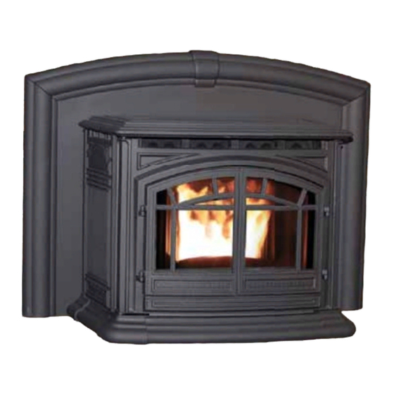
M55C-FPI
Pellet Stove
OWNER'S MANUAL
PLEASE READ THIS ENTIRE MANUAL BEFORE INSTALLATION AND USE
OF THIS PELLET-BURNING ROOM HEATER. FAILURE TO FOLLOW THESE
INSTRUCTIONS COULD RESULT IN PROPERTY DAMAGE, BODILY INJURY OR
EVEN DEATH.
Contact your building or fire officials about restrictions
and installation inspection requirements in your area.
50-2257
Advertisement
Table of Contents

Related Manuals for Enviro M55C-FPI


Summary of Contents for Enviro M55C-FPI
- Page 1 - without changing any parts! SHERWOOD INDUSTRIES IS AN ENVIRONMENTALLY RESPONSIBLE COMPANY. THIS MANUAL IS PRINTED ON RECYCLED PAPER. PLEASE KEEP THESE INSTRUCTIONS FOR FUTURE REFERENCE M55C-FPI Pellet Stove OWNER’S MANUAL PLEASE READ THIS ENTIRE MANUAL BEFORE INSTALLATION AND USE OF THIS PELLET-BURNING ROOM HEATER.
-
Page 2: Table Of Contents
Table of Contents Introduction.......................3 Rating Label Location....................3 Fuel Quality........................3 Safety Warnings & Recommendations..................4 Operating Instructions......................6 Dimensions & Specifications..................6 Control Board Functions....................7 Automatic Safety Features of Your Pellet Stove............7 Operating Your Pellet Stove..................8 Turning Your Pellet Stove Off..................9 Slider/Damper Set-Up....................9 Routine Cleaning and Maintenance..................10 Optional Service Rail Kit....................13 Technical Installation Instructions..................14 Deciding Where to Locate Your Pellet Appliance............15... -
Page 3: Introduction
Fuel quality is important, please read the following: Your Enviro pellet stove has been designed to burn ¼” (6mm) dia wood pellets and other organic fuels. DO NOT use this appliance as an incinerator. DO NOT use unsuitable and non recommended fuels, including liquid fuels as this will void any warranties stated in this manual. -
Page 4: Safety Warnings & Recommendations
To prevent the possibility of a fire, ensure that the appliance is properly installed by adhering to the installation instructions. An Enviro dealer will be happy to assist you in obtaining information with regards to your local building codes and installation restrictions. - Page 5 If this power cord should become damaged, a replacement power cord must be purchased from the manufacturer or a qualified Enviro dealer. Be careful that the electrical cord is not trapped under the appliance and that it is clear of any hot surfaces or sharp edges. This unit’s maximum power requirement is 504 watts.
-
Page 6: Dimensions & Specifications
16 1/8" 24 3/4" 26 7/8" 12" 32 7/8" 23" 44" Figure 1: Dimensions of M55C-FPI. peciFicationS Input rating when using: Wood Pellets/Corn - 55,000BTU (16.1KW•hr) & Wheat/Barley - 53,000BTU (15.5KW•hr). Table 1: M55C-FPI Specifications. Description Fuel type Residential Pellet Heater 6mm (¼”) dia. -
Page 7: Operating Instructions
Operating Instructions ontRoL oaRd unctionS Note: The Control Panel is located underneath the units Cast Hopper Lid which is attached to a safety switch that will immediatley stop the auger. The switch will stop operation of the stove and display a #4 flash code if the lid is not closed within two minutes. -
Page 8: Operating Your Pellet Stove
Operating Instructions peRating eLLet tove THE UNIT WILL NOT OPERATE WITH THE DOOR OR ASH BOX OPEN. Open the hopper lid only to re- fuel or to adjust the controls. the unit will shut down if the hopper lid is left open for longer than two minutes. -
Page 9: Turning Your Pellet Stove Off
Operating Instructions setting. If the thermostat contacts remain open, the stove automatically begins its shutdown routine. The stove will re-light when the thermostat contacts close again. uRning eLLet tove • MANUAL and HI / LOW mode: To turn the unit OFF, simply press the ON / OFF button. This will stop the feed of pellets. -
Page 10: Routine Cleaning And Maintenance
10. Set the fire grate in place, it should sit level on the front and back of the burn pot liner. Lock it in with the lever on the burn Burn Pot pot. 11. Close the door Figure 8: M55C-FPI Burn Pot Assembly. - Page 11 Cleaning of the glass must only be done when stove is cold. Open the door by lifting the handle. Figure 9: M55C-FPI Heat Exchanger Cleaning. The glass can be cleaned by wiping down the outside and inside of the glass with a dry soft cloth.
- Page 12 ASH PAN 6. Re-install the parts in Figure 10: M55C-FPI Exhaust Passages. reverse order 7. Close all doors securely. BLOWER MECHANISMS (Annually) Unplug the stove and pull the unit forward to access the two blowers. Vacuum all dust from motors.
-
Page 13: Optional Service Rail Kit
Fig. 12. 6. Adjust leg height and lock them in using the thumb screws. (Fig 12) 7. Slide unit forward on rails. Figure 11: M55C-FPI with Service Rail Kit Quick Release Pin Thumb Screw Figure 12: Close up of Front Rail... -
Page 14: Technical Installation Instructions
Technical installation instructions FoR QuaLiFied inStaLLeRS onLy... -
Page 15: Deciding Where To Locate Your Pellet Appliance
Installation eciding HeRe to ocate youR eLLet ppLiance 1. Unit must be installed in a masonry fireplace. 2. Do not install the stove in a bedroom or room where people sleep in. 3. Locate the stove in a large and open room that is centrally located in the house. This will optimize heat circulation. -
Page 16: Installing The Inset Frame And Levelling
5. Adjust the top anchor bolts to secure it to the lintel. Ready-rod may be substituted if the bolts are not long enough. Anchor Bolts NOTE: Surround Panel removed for clarity Levelling Bolts Figure 4: M55C-FPI Frame. -
Page 17: Clearances To Combustibles
Pour éteindre eur. Figure 4: M55C-FPI Clearance to Combustibles. MODE "AUTO CAUTION: ATTENTION: HeRmoStat nStaLLation L'APPAREIL EST CHAUD LORSQU'IL HOT WHILE IN OPERATION. DO 1. -
Page 18: Vent Termination Requirements
Installation eRmination eQuiRementS IT IS RECOMMENDED THAT YOUR PELLET STOVE BE INSTALLED BY AN AUTHORIZED DEALER/INSTALLER. Table 2: Use in conjunction with Figure 6 for allowable exterior vent termination locations. Letter Minimum Clearance Description 24 in (61 cm) Above grass, top of plants, wood, or any other combustible materials. 48 in (122 cm) Beside/below any door or window that may be opened. -
Page 19: Outside Fresh Air Connection
Base of unit to center of 16.273 intake ” (130 mm) 5.120 Center of unit to center of intake 5” (128 mm) 3.000 4.952 9.624 Figure 8: M55C-FPI Inlet and Outlet Location. DATE: 20/7/2010 SHERWOOD INDUSTRIES LTD. SPECIAL NOTE: BACK VIEW DESC:... -
Page 20: Masonry Fireplace Installation
Installation Installation aSonRy iRepLace nStaLLation Rain Cap non-combustible manufactured Steel Plate or Flashing hearth pad (min. 24 gauge galvanized steel or similar) must cover combustible flooring underneath, as well as 6” (150 Flexible or Rigid 4" mm) in front of the heater and 6” (150 Stainless Steel Liner mm) to the side of the heater. -
Page 21: Positive Flue Connection
Installation (uSa o oSitive onnection WitHout a eLine This unit does not require a full reline (in USA only) when installing into a masonry fireplace, however, it is recommended to ensure proper drafting of the appliance. IMPORTANT: Ensure the chimney and firebox are cleaned and free of all debris, including soot and ashes, before proceeding with this installation. -
Page 22: Built-In Installation
Installation without a masonry fireplace - The M55C-FPI can be installed without an existing masonry fireplace by building an enclosure for the unit to be installed in. This enclosure must be a minimum of 18” deep, 36” wide and 23-1/4” high and made with ½”... -
Page 23: Horizontal Exhaust Through Wall Installation
Installation oRizontaL XHauSt HRougH nStaLLation Vent installation: install vent at clearances specified by the vent manufacturer. A chimney connector shall not pass through an attic or roof space, closet or similar concealed spaces, or a floor, or ceiling. Where passage through a wall or partition of combustible construction is desired, the installation must conform to CAN/CSA-B365 Installation Code for Solid-Fuel-Burning Appliances and Equipment and with all local regulations, including those referring to regional and national. -
Page 24: Through Wall With Vertical Rise And Horizontal Termination Installation
Installation Recommended - t HRougH eRticaL iSe and oRizontaL eRmination nStaLLation NOTE - This venting configuration is only for use with the Built-In installation. Termination cap 90°elbow Wall framing Vertical section of vent pipe Wall strap Horizontal frame for thimble Clean out tee Wall thimble... -
Page 25: Outside Vertical Installation
Installation utSide eRticaL nStaLLationS To accomplish an outside vertical pipe installation, follow the “H ” orizontal xHauSt HrougH nStallationS section and then finish it by performing the following. 1. Install a tee with clean out on the outside of the house. 2. -
Page 26: Inside Vertical Installation
Installation nSide eRticaL nStaLLationS 1. Install a tee or 90° elbow on the inside of the house. 2. Install PL vent upward from the tee. Make sure that you install support brackets to keep the vent straight and secure. All joints in the exhaust venting system must be fastened with at least three (3) screws. -
Page 27: Troubleshooting
Troubleshooting DO NOT: ● Service the stove with wet hands. The stove is an electrical appliance, which may pose a shock hazard if handled improperly. Only qualified technicians should deal with possible internal electrical failures. ● Do not remove from the firebox any screws without penetrating oil lubrication. WHAT TO DO IF: 1. - Page 28 Troubleshooting • Exhaust Temperature Sensor failure. Bypass sensor located on Exhaust Blower, if stove now operates properly, the unit may require cleaning or a new sensor. Contact your local dealer for service. • Check the agitator to make sure it is turning properly 3.
- Page 29 Troubleshooting 7. The convection blower will not function normally. • Check the line fuse to see if it has blown. • Clean all grill openings at the back and below unit . • Check the Voltage across the blower wires, It should adjust with the heat output settings. If not contact your local dealer for service.
-
Page 30: Wiring Diagram
Wiring Diagram Black Brown 2µF Capacitor Black Exhaust Blue Combustion Temperature Brown Blower Blue Blue Sensor Black White 120V Ground Air Pump White Plug Green Ground Ignitor White Ground Thermostat White Agitator Blue/Yellow Black Motor White Auger Yellow Yellow Motor Purple Brown Blue... -
Page 31: Parts List
50-2155 OPTION Pellet Stove Thermostat 50-1971 OPTION Glass Tinted M55C 50-2247 OPTION M55C-FPI Service Rails 50-2262 Hopper Switch 50-2052 High Limit Temp Sensor 200°F (93°C) Manual Reset EF-016 120°F (49°C) Ceramic Fan Temp Sensor EC-001 ⅝” I.D. Auger Brass Bushings (Set of 2) - Page 32 50-2288 Burn Pot Scraper Tool 50-1254 Door And Ash Door Gasket /16 Firm - 10ft (3.05m) 50-2058 M55C-FPI Cast Front Mounting Brackets (Set of 2) 50-2289 4” Exhaust Starter Tube C/W Gasket 50-2290 Cast Fluted Firebox Liner 50-2291 Pedestal & Ash Pan Gasket - 10ft (3.05m)
- Page 33 M55C-FPI Cast Ash Door - Beach 50-2276 M55C-FPI Cast Ash Door - Chestnut 50-2282 M55C-FPI Cast Ash Door - DB 50-2299 M55C-FPI Cast Surround Trim Only - PD 50-2272 M55C-FPI Cast Surround Trim Only - Beach 50-2278 M55C-FPI Cast Surround Trim Only - Chestnut 50-2284...
-
Page 34: Parts Diagram - Components
Parts Diagram - Components... -
Page 35: Parts Diagram - Steel
Parts Diagram - Steel... -
Page 36: Warranty
Sherwood Industries Ltd. (“Sherwood”) hereby warrants, subject to the terms and conditions herein set forth, this product against defects in material and workmanship An expanded list of exclusions is available at www.enviro.com/help/warranty.html during the specified warranty period starting from the date of original purchase at retail. -
Page 37: Installation Data Sheet
_________________________________________ _________________________________________ ADDRESS: ADDRESS: _________________________________________ _________________________________________ _________________________________________ _________________________________________ _________________________________________ _________________________________________ PHONE:___________________________________ PHONE:___________________________________ NAME OF INSTALLER: MODEL: M55C-FPI SERIAL NUMBER:___________________________ _________________________________________ DATE OF PURCHASE: _____________ (dd/mm/yyyy) ADDRESS: DATE OF INSTALLATION:___________ (dd/mm/yyyy) _________________________________________ MAGNEHELIC AT INSTALL:___________________ _________________________________________ INSTALLER’S SIGNATURE: _________________________________________ _________________________________________ PHONE:___________________________________ MANUFACTURED BY: SHERWOOD INDUSTRIES LTD.
Need help?
Do you have a question about the M55C-FPI and is the answer not in the manual?
Questions and answers