Enviro Mini A Technical Manual
Hide thumbs
Also See for Mini A:
- Owner's manual (38 pages) ,
- Service manual (77 pages) ,
- Technical manual (34 pages)
Table of Contents
Advertisement
SHERWOOD INDUSTRIES IS AN ENVIRONMENTALLY RESPONSIBLE COMPANY. THIS MANUAL IS PRINTED ON RECYCLED PAPER.
PLEASE KEEP THESE INSTRUCTIONS FOR FUTURE REFERENCE
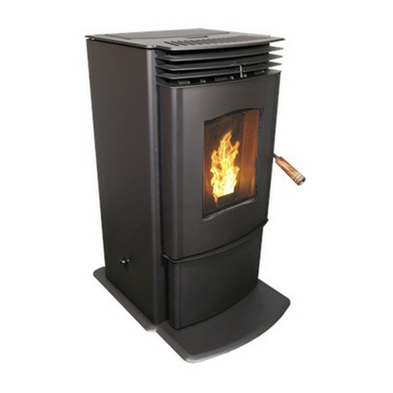
PELLET STOVE
Mini A
TECHNICAL MANUAL
PLEASE READ THIS ENTIRE MANUAL BEFORE
INSTALLATION AND USE OF THIS PELLET BURNING
ROOM HEATER. FAILURE TO FOLLOW THESE
INSTRUCTIONS COULD RESULT IN PROPERTY DAMAGE,
BODILY INJURY OR EVEN DEATH
Contact your building or fire officials about restrictions and installation
inspection requirements in your area.
50-1928
Advertisement
Table of Contents

Related Manuals for Enviro Mini A


Summary of Contents for Enviro Mini A
- Page 1 SHERWOOD INDUSTRIES IS AN ENVIRONMENTALLY RESPONSIBLE COMPANY. THIS MANUAL IS PRINTED ON RECYCLED PAPER. PLEASE KEEP THESE INSTRUCTIONS FOR FUTURE REFERENCE PELLET STOVE Mini A TECHNICAL MANUAL PLEASE READ THIS ENTIRE MANUAL BEFORE INSTALLATION AND USE OF THIS PELLET BURNING ROOM HEATER.
-
Page 2: Table Of Contents
Table of Contents Introduction...........................3 Rating Label Location........................3 Safety Warnings And Recommendations..................3 Installation.............................6 Deciding Where to Locate your Pellet Appliance................6 Removing Pellet Stove From Pallet.....................6 Appliance Dimensions and Specifications..................7 Hearth Pad (50-1219) Installation....................7 Clearances to Combustibles.......................8 Alcove Clearances........................8 Vent Termination Requirements....................9 Outside Fresh-Air Connection....................10 Exhaust and Intake Locations....................10 Mobile Home Installation......................11... -
Page 3: Introduction
To prevent the possibility of a fire, ensure that the appliance is properly installed by adhering to the installation instructions. An ENVIRO dealer will be happy to assist you in obtaining information with regards to your local building codes and installation restrictions. - Page 4 If this power cord should become damaged, a replacement power cord must be purchased from a qualified ENVIRO dealer. Be careful that the electrical cord is not trapped under the appliance and that it is clear of any hot surfaces or sharp edges. This unit’s maximum power requirement is 184 watts (600 watts peak).
- Page 5 Introduction INSTALLATION: Contact your local building or fire official to obtain a permit and any information on installation restrictions and inspection requirements for your area. All local regulations, including those referring to national and European Standards need to be complied with when installing this appliance. Be sure to maintain the structural integrity of your home when passing a vent through walls, ceilings, or roofs.
-
Page 6: Installation
Installation ECIDING HERE TO OCATE YOUR ELLET PPLIANCE 1. Check clearances to combustibles. 2. Do not obtain combustion air from an attic, garage or any unventilated space. Combustion air may be obtained from a ventilated crawlspace. 3. Do not install the stove in a bedroom. 4. - Page 7 Installation EMOVING ELLET TOVE ALLET AND NSTALLING EARTH Tool Required: ● T-20 screwdriver ● ” socket or flat head screwdriver Installation: 1. Slide a hearth pad tab through each of the three (3) slots on the hearth pad so the slotted end is up and Figure 3: Screw behind ash box.
-
Page 8: Clearances To Combustibles
Installation LEARANCES TO OMBUSTIBLES IMPORTANT: Attach the Mini’s Hearth Pad when installing the unit on a combustible floor. The supplied hearth pad meet all the requirement of a proper hearth pad. If you do not use the supplied hearth pad a hearth pad must be used when on combustible material. - Page 9 Installation ERMINATION EQUIREMENTS IT IS RECOMMENDED THAT YOUR PELLET STOVE BE INSTALLED BY AN AUTHORIZED DEALER/INSTALLER. Table 1: Use in conjunction with Figure 9 for allowable exterior vent termination locations. Letter Minimum Clearance Description 24 in (61 cm) Above grass, top of plants, wood, or any other combustible materials. 48 in (122 cm) Beside/below any door or window that may be opened.
- Page 10 Installation UTSIDE RESH ONNECTION Outside fresh air is mandatory when installing this unit in airtight homes and mobile homes. A Fresh-air intake is strongly recommended for ������� ���� all installations. Failure to install intake air may result in improper combustion as well as the unit smoking during power failures.
-
Page 11: Mobile Home Installation
(3) screws evenly spaced. CAUTION: THE STRUCTURAL INTEGRITY OF THE MANUFACTURED HOME FLOOR, ENVIRO Mini WALL AND CEILING/ROOF MUST Optional Hearth Pad BE MAINTAINED. Flooring Steel Frame ”... -
Page 12: Horizontal Exhaust Through Wall Installation
Installation ORIZONTAL XHAUST HROUGH NSTALLATION Vent installation: install vent at clearances specified by the vent manufacturer. A chimney connector shall not pass through an attic or roof space, closet or similar concealed spaces, or a floor, or ceiling. Where passage through a wall or partition of combustible construction is desired, the installation shall conform to CAN/CSA-B365 Installation Code for Solid-Fuel-Burning Appliances and Equipment. -
Page 13: Through Wall With Vertical Rise And Horizontal Termination Installation - Freestanding
Installation 9. The pipe must extend at least 12” (30 cm) away from the building. If necessary, bring another length of pipe (PL type) to the outside of the home to connect to the first section. Do not forget to place high temperature silicone around the pipe that passes through the thimble. -
Page 14: Inside Vertical Installations
Installation NSIDE ERTICAL NSTALLATIONS 1. Choose a stove location that is ideal. See the ���� ��� ������� ��� �� section “D ECIDING HERE TO OCATE YOUR ELLET �� ����� ��� ����� ��� � �� .” ���� �� ��� ������ ������ PPLIANCE ����... -
Page 15: Hearth Mount Installation
���� ��� ����� ����� �� �������� Installation �������� �� ����� �� ��������� ����� ����� EARTH OUNT NSTALLATION ������ ������� �� �������� ���� Refer to Figures 20 and 21. ��� ����� ��� ������ ������� �� ��� ��� 1. Install the hearth pad. ����... -
Page 16: Exterior Mounted Exhaust Blower (20-070)
Installation (20-070): XTERIOR OUNTED XHAUST LOWER The Mini can be equipped with an externally mounted exhaust blower. This optional kit includes all components necessary to install the exhaust blower on any vertical wall surface. Choose a location for your stove that meets the requirements stated in your manual and allows installation with the least amount of interference with house framing, plumbing, wiring, etc. -
Page 17: Typical Through Wall With Exterior Blower Kit Installation - Horizontal Termination
Installation YPICAL HROUGH XTERIOR LOWER NSTALLATION ORIZONTAL ERMINATION 90° Elbow 45°Elbow with Rodent screen or stainless steel termination hood 2ft (610mm) Riser Pipe Adaptor Exterior Blower and Housing Electrical Cable Figure 25: Through Wall Installation with Exterior Blower Kit. NOTE: Ensure that all interior vent connections are sealed by placing a small bead of high temperature silicone around each chimney connection. -
Page 18: Thermostat Installation
Installation YPICAL HROUGH XTERIOR LOWER NSTALLATION ERTICAL ERMINATION Roof Sheathing Rain Cap Roof Flashing Roof Rafters Ceiling Joists Follow the previous pages for through wall installations. Ensure that vent pipe is properly secured to wall using wall straps. Maintain clearances to combustibles on vent pipe as well as unit. -
Page 19: Slider/Damper Set-Up
Installation LIDER AMPER This is used to regulate the airflow through the pellet stove. The slider damper should be initially set by a trained technician using magnehelic. The slider damper knob is located on the left side of the stove. The combustion exhaust blower is a variable speed blower controlled by the heat output button. -
Page 20: Troubleshooting
Troubleshooting DO NOT: ● Service the stove with wet hands. The stove is an electrical appliance, which may pose a shock hazard if handled improperly. Only qualified technicians should deal with possible internal electrical failures. ● Do not remove from the firebox any screws without penetrating oil lubrication. WHAT TO DO IF: 1. -
Page 21: Wiring Diagram
Troubleshooting üPoor Quality Fuel – Insufficient energy in the fuel to produce enough heat to keep the stove burning or operational. üExhaust Temperature Sensor failure. – Bypass sensor located on Exhaust Blower if stove now operates properly, the unit may require cleaning or a new sensor. Contact your local dealer for service. üCheck the fuse on the circuit board. - Page 22 Troubleshooting 7. The convection blower will not function normally. üClean all grill openings at the back and below unit . üPress the fan button; does the fan come on? Press again to verify that the blower turns on; if, not contact your local dealer for service.
-
Page 23: Wiring Diagram
Wiring Diagram Armor Cable Supplied Grey Optional Exterior Vacuum Exhaust Blower Grey Switch Black White White Combustion Blue Brown Blower Exhaust Temperature Sensor Power Cord Brown Ground Black 115V 115V White Black Black White 220V 220V Brown Blue Thermostat Common 5 Amp Fuse Ignitor... -
Page 24: Parts List
Parts List Reference Description Part Number Number 120°F (49°C) Ceramic Fan Temperature Sensor EC-001 Auger Motor - 115V EF-001 High Limit Temp Sensor 200°F (93°C) Manual Reset EF-016 Vacuum Switch - 115V EF-017 Silicone Hose EF-018 Aluminum Hose Barb EF-019 Shoulder Bolt, Hardened Bushing &... - Page 25 Parts List Reference Description Part Number Number Auger 50-1161 Firebox Panel Set with Insulation 50-1162 Front Louvers 50-1169 Lid Set 50-1171 Stove Top Assembly 50-1172 Hopper Guard 50-1174 Handle Bracket 50-1177 Draft Slider 50-1178 Ash Pan Cover 50-1180 Ash Pan 50-1181 Ash Shelf Louver 50-1182...
-
Page 26: Parts Diagram - Components
Parts Diagram - Components �� �� � �� �� �� � � �� �� �� � �� � A UT O /O H IG N UA � A IR T IO � �� �� Mini - Components September 2008... -
Page 27: Parts Diagram - Steel
Parts Diagram - Steel... -
Page 28: Warranty
Industries, our commitment to the highest level of quality and customer service is the most important thing we do. Each Enviro stove is built on a tradition of using only the finest materials and is backed by our Exclusive Lifetime Limited Warranty to the original purchaser. With Enviro, you’re not just buying a stove, you’re buying a company with years of unequalled performance and quality. - Page 29 Limited Warranty on this stove. If unsure as to the extent of this Limited Warranty, contact your authorized Enviro dealer before installation. 10. Sherwood Industries Ltd. will not be responsible for inadequate performance caused by environmental conditions.
- Page 30 If the stove is used for commercial purposes, it is excluded from the Limited Warranty. 24. No dealer, distributor, or similar person has the authority to represent or warrant Enviro products beyond the terms contained within the Limited Warranty. Sherwood Industries Ltd. assumes no liability for such warranties or representations.
-
Page 31: Installation Data Sheet
SERIAL NUMBER:___________________________ _________________________________________ DATE OF PURCHASE: _____________ (dd/mm/yyyy) DATE OF INSTALLATION:___________ ADDRESS: (dd/mm/yyyy) MAGNEHELIC AT INSTALL:___________________ _________________________________________ INSTALLER’S SIGNATURE: _________________________________________ _________________________________________ _________________________________________ PHONE:___________________________________ MANUFACTURED BY: SHERWOOD INDUSTRIES LTD. 6782 OLDFIELD RD. SAANICHTON, BC, CANADA V8M 2A3 www.enviro.com September 17, 2008 C-11624...
Need help?
Do you have a question about the Mini A and is the answer not in the manual?
Questions and answers