
Related Manuals for Data Translation DT3120


Summary of Contents for Data Translation DT3120
- Page 1 (217) 352-9330 | Click HERE Find the Measurement Computing / Data Translation DT3120 at our website:...
- Page 2 UM-18109-E DT3120 User’s Manual...
- Page 3 Fifth Edition Copyright © 2001, 2002 by Data Translation, September, 2002 Inc. All rights reserved. Information furnished by Data Translation, Inc. is believed to be accurate and reliable; however, no responsibility is assumed by Data Translation, Inc. for its use; nor for any infringements of patents or other rights of third parties which may result from its use.
- Page 4 Changes or modifications to this equipment not expressly approved by Data Translation could void your authority to operate the equipment under Part 15 of the FCC Rules. Note: This product was FCC-Certified under test conditions that included use of shielded cables and connectors between system components.
-
Page 6: Table Of Contents
Table of Contents About this Manual ........Intended Audience. - Page 7 Chapter 3: Supported Device Driver Capabilities..DT3120 Device Driver Capabilities ......
- Page 8 Contents Appendix B: Modifying the Device Driver ... . . Windows 98 and Windows Me Procedures ....Adding a Board to the Device Driver Configuration.
- Page 9 Contents viii...
-
Page 10: About This Manual
About this Manual This manual describes the features of the DT3120 frame grabber board, and how to use the DT3120 Device Driver with the Frame Grabber SDK to write an application program. Intended Audience This document is intended for engineers, scientists, technicians, or others responsible for programming and/or using a DT3120 board to perform machine vision and/or image analysis operations. -
Page 11: Conventions Used In This Manual
DT3120 Device Driver and the initialized control values. • Chapter “Programming Flowcharts,” describes the processes you must follow to program the DT3120 board using the DT-Open Layers Frame Grabber SDK. • Chapter “Troubleshooting,” provides information that you can use to resolve problems with the boards and the device driver, should they occur. -
Page 12: Related Information
Imaging OMNI CD or GLI/2 Streamline CD provided with the DT3120 board, describes how to install the DT3120 software, install a DT3120 board, connect signals to the board, install and configure the DT3120 Device Driver, verify the board’s operation with DT-Acquire, and view the DT3120 manuals online. - Page 13 About this Manual Additionally, it may be helpful to read other material to gain a better understanding of image processing concepts, algorithms, and their applications. Data Translation's Technical Support Department recommends the following resources for understanding image processing concepts, processing, and coding: Baxes, Gregory A.
- Page 14 About this Manual Held, Gilbert. Data Compression Techniques and Applications: Hardware and Software Considerations. 3rd ed. Somerset, NJ: John Wiley & Sons, Inc., 1991. Covers various techniques currently used for data compression; includes programming examples. Holzmann, Gerard J. Beyond Photography - The Digital Darkroom. Englewood Cliffs, NJ: Prentice-Hall, 1988.
- Page 15 About this Manual Reid, Christopher E. and Thomas B. Passin. Signal Processing in C. Somerset, NJ: John Wiley & Sons, Inc. Rimmer, Steve. Bit-Mapped Graphics. Blue Ridge Summit, PA: Tab Books, Inc., 1990. Details digital image file formats and image manipulation after digitizing.
-
Page 16: Where To Get Help
Press, 1990. Provides an in-depth description of digital video fundamentals. Where to Get Help Should you run into problems installing or using a DT3120 board, the Data Translation Technical Support Department is available to provide technical assistance. Refer to Chapter 5 for more information. - Page 17 About this Manual...
-
Page 18: Chapter 1: Overview
Overview Features ..........Supported Software . -
Page 19: Features
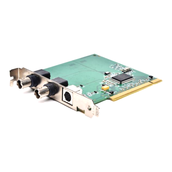
Chapter 1 Features The DT3120 is a low-cost, color frame grabber board for the PCI bus. This board is suitable for both color image analysis and machine vision applications. Each DT3120 board digitizes the image, then either stores the digitized data to the host computer’s system memory or transfers the digitized data to the computer’s display controller to display images... -
Page 20: Supported Software
Imaging OMNI CD, which is shipped with the board. You must install this device driver to use a DT3120 board with any of the supported software packages or utilities. Refer to the DT3120 Getting Started Manual (UM-18113) for information on installing the device driver. - Page 21 Chapter 1 Refer to the Data Translation catalog for information on additional software packages available for the DT3120 board.
-
Page 22: Chapter 2: Principles Of Operation
Principles of Operation Video Input Signals ........Sync Signals. - Page 23 Chapter 2 To aid the discussions in this chapter, refer to the block diagram of the DT3120 board, shown in Figure 1. Bold signal names indicate signals you can access. Video Input Programmable Image Scaling Programmable Image Cropping FIFO External...
-
Page 24: Video Input Signals
• Pixel clock, and • Triggers. Video Signal Types The DT3120 can acquire images from the following signal types: • Monochrome − Data is represented as 8-bit grayscale values. • Composite (CVBS) − The Color Video Broadcast Standard, where both luminance and chrominance information is encoded on a single composite video signal. -
Page 25: Videos Input Channels
The DT3120 board accepts one composite (CVSB) or one S-video input source at a time. Connect the composite input to connector J2 connector on the DT3120 board or connect the S-video input to connector J 3 on the DT3120 board. -
Page 26: Color Intensity
255 (in increments of 1); the nominal value is 128. Pixel Clock The DT3120 generates a 12.5 MHz pixel clock signal for 60 Hz image formats and a 15 MHz pixel clock signal for 50 Hz image formats. Pixels are available to the DT3120 frame grabber board in increments... -
Page 27: Triggers
Chapter 2 Triggers DT3120 board can accept one of the following trigger sources: • A software trigger − The board can acquire a frame when a software command is issued. • An external trigger − By attaching a digital signal to connector J1 on the board, you can synchronize frame acquisitions with external events. -
Page 28: Sync Signals
Principles of Operation Sync Signals To digitize the incoming video signal, the DT3120 board requires both horizontal and vertical sync signals. The board determines this information, as well as the odd and even fields, from the video input signal being digitized. -
Page 29: Video Area
Chapter 2 Video Area The total video area is a complete set of horizontal and vertical input lines from which you extract the active video area and the frame within the active video area. The total video area includes all parts of the signal, including nonvisual portions such as horizontal and vertical blanking information. -
Page 30: Horizontal Video Signal
Principles of Operation Horizontal Video Signal Each line of video comprising the total video area contains blanking information and active video. Figure 2 shows the components of a single horizontal line of video. Note that the frame is an area that you establish within the active video area. -
Page 31: Vertical Video Signal
Chapter 2 Vertical Video Signal Each field of video also contains blanking information and lines of active video. Figure 3 shows the components of a single vertical field of noninterlaced video. Note that the frame is an area that you establish within the active video area. -
Page 32: Frame (Region Of Interest)
The width of the frame is the number of pixels per line of video. The height of the frame is the number of lines per field. Table 1 shows the settings you can program on the DT3120 board to define the frame. Figure 4 illustrates these relationships. - Page 33 Chapter 2 Table 1: Frame Settings for the DT3120 Board Nominal Setting Description Range Values Frame Left The first pixel in the region 50 Hz: 0 to 763 pixels of interest, relative to the 60 Hz: 0 to 635 pixels first active pixel, to digitize.
-
Page 34: Types Of Frames
Figure 4: Spatial Relationship of Video Signal Types of Frames The DT3120 board can acquire interlaced frames. The video signal is defined as two consecutive fields, where the start of each field is identified by the falling edge of the vertical sync. -
Page 35: Scaling Frames
If the next field is even, only the even fields are acquired. Scaling Frames DT3120 board can perform simultaneous, interpolated, arbitrary scaling in real-time. This feature is useful if you want to reduce the size of an image. The number of lines per frame in the scaled image can range from 1 to 480 for 60 Hz image formats or from 1 to 576 for 50 Hz image formats (in increments of 1). -
Page 36: Frame Storage Mode
Principles of Operation Frame Storage Mode You can store the data in one of the following formats: • Monochrome format (8-bits per pixel), as shown in Figure • RGB16 (16-bits per pixel), as shown in Figure • RGB24 (24-bits per pixel), as shown in Figure 7;... - Page 37 Chapter 2 Address Byte Format RGB1 RGB2 RGB3 RGB4 Address DWORD Format RGB1 RGB2 RGB3 RGB4 Figure 6: RGB16 (16-Bit) Color Data Format Address 0 Byte Format Address DWORD Format G2B2R3B3 R1G1B1R2 Figure 7: RGB 24-Bit Color Data Format...
- Page 38 Principles of Operation Address 0 Byte Format Address DWORD Format R2G2B2X1 R1G1B1X1 Figure 8: RGB 32-Bit Color Data Format Address Y4U2Y5V2 Y6U3Y7V3 Y2U1Y3V1 Byte Format Y0U0Y1V0 Address DWORD Format YUYV0 YUYV1 YUYV2 YUYV3 Figure 9: YUYV422 (16-Bit) Data Format...
-
Page 39: Passthru Operations
Chapter 2 Passthru Operations In a passthru operation, a DT3120 board continuously captures and displays video data until you stop the operation. Typically, you use passthru to view images (in as close to real time as possible for the configuration and passthru method chosen) for the purpose of focusing or positioning the camera. -
Page 40: Continuous-Acquire Passthru Mode
A passthru operation continues until you stop it. You can stop an asynchronous bitmap passthru operation using software. Continuous-Acquire Passthru Mode The DT3120 board supports asynchronous, continuous-acquire passthru mode. Since it is asynchronous, the operation starts but gives control to you immediately, allowing you to perform other operations while data is acquired and/or displayed. -
Page 41: Source Origin
On the DT3120 board, the source origin is always 0,0. Passthru Scaling On a DT3120 board, the same scaling mechanism that is used to scale frames is used to scale passthru images. The number of lines per frame in the scaled image can range from 1 to 480 for 60 Hz image formats or from 1 to 576 for 50 Hz image formats (in increments of 1). -
Page 42: Overlays
Principles of Operation Overlays You can add overlays to the display using software during passthru operations. Overlays allow you to place an image on top of another image that was captured using passthru. Note: Overlays require Direct Draw Interface (DDI) support. -
Page 43: Acquisition Operations
Using the DT3120, you can acquire a single full frame, a single field (subframe), multiple full frames, or multiple fields. Data is stored to an area in system memory that is allocated by the DT3120 Device Driver (called device memory). - Page 44 PCI bus assigns the interrupt to the board automatically when it is installed. The speed of the PCI bus allows the DT3120 to transfer an unlimited number of consecutive frames across the bus in real time. You can acquire consecutive images, up to the capacity of available system RAM.
- Page 45 Chapter 2...
-
Page 46: Chapter 3: Supported Device Driver Capabilities
Capabilities DT3120 Device Driver Capabilities ......Initialized Control Values ....... . -
Page 47: Dt3120 Device Driver Capabilities
DT3120 Device Driver Capabilities Because the Frame Grabber SDK is intended to be used with all DT-Open Layers frame grabbers, the DT3120 may not support all of the Frame Grabber SDK capabilities or may support the Frame Grabber SDK capabilities differently from other boards. - Page 48 Supported Device Driver Capabilities For capabilities Refer to the table that apply to ... starting on ... Overlay page 47 Memory page 48 Acquisition page 49 Digital I/O page 51 Note: If your code is intended to be compatible with various Data Translation products, use the query functions to determine that the capability is supported by the installed board, prior to execution.
- Page 49 Chapter 3 Table 3: General Device Capabilities for the DT3120 Device Driver Capability DT3120 Support OlImgQueryDeviceCaps Board Signature OLC_IMG_DC_OL_SIGNATURE 0x44544F4C Device ID OLC_IMG_DC_DEVICE_ID 8080h Board Name OLC_IMG_DC_DEVICE_NAME “DT3120” Device Type OLC_IMG_DC_OL_DEVICE_TYPE Monochrome Frame Grabber OLC_IMG_DEV_MONO_FRAME_GRABBER Color Frame Grabber OLC_IMG_DEV_COLOR_FRAME_GRABBER Sections Supported...
- Page 50 Supported Device Driver Capabilities Table 3: General Device Capabilities for the DT3120 Device Driver (cont.) Capability DT3120 Support DtColorQueryInterface SDK Extension Capabilities OLT_QUERY_COLOR_INTERFACE Supports Signal Type COLOR_INTERFACE_SIGNAL_TYPE True Supports Storage Mode COLOR_INTERFACE_STORAGE_MODE True Supports Image Parameter COLOR_INTERFACE_IMAGE_PARAMETER True Supports Hardware Scaling...
- Page 51 Chapter 3 Table 4: Input Signal Capabilities for the DT3120 Device Driver Capability DT3120 Support OlFgQueryInputCaps Number of Input Sources OLC_FG_INPUT_SOURCE_COUNT Supports Input Filter Selection OLC_FG_IC_DOES_INPUT_FILTER Supports Input Filter Query OLC_FG_IC_DOES_QUERY_INPUT_FILTER Supported Filters OLC_FG_IC_INPUT_FILTER_LIMITS AC Coupled, no Input Filter OLC_FG_FILT_AC_NONE...
- Page 52 Supported Device Driver Capabilities Table 4: Input Signal Capabilities for the DT3120 Device Driver (cont.) Capability DT3120 Support Range of Internal Input Clock Frequency, in Hz OLC_FG_IC_CLOCK_FREQ_LIMITS Fixed 50 Hz: 15,000,000 60 Hz: 12,500,000 Clock Sources OLC_FG_IC_CLOCK_SOURCE_LIMITS Supports Internal Clock...
- Page 53 Chapter 3 Table 4: Input Signal Capabilities for the DT3120 Device Driver (cont.) Capability DT3120 Support Strobing Modes For Each Input Group OLC_FG_IC_STROBE_TYPE_LIMITS Can Strobe After Each Field OLC_FG_STROBE_FIELD_BASED Can Strobe After Each Frame OLC_FG_STROBE_FRAME_BASED Can Strobe On A Software Command...
- Page 54 Supported Device Driver Capabilities Table 4: Input Signal Capabilities for the DT3120 Device Driver (cont.) Capability DT3120 Support DtColorImageParameters Image Parameters in the SDK Extensions OLT_COLOR_PARAMETER Brightness Values OLC_SET_BRIGHTNESS min: 0 max: 255 nominal: 128 granularity: 1 Contrast Values OLC_SET_CONTRAST...
- Page 55 Chapter 3 Table 4: Input Signal Capabilities for the DT3120 Device Driver (cont.) Capability DT3120 Support Image Parameters in the SDK Extensions OLT_COLOR_PARAMETER Red Level Values OLC_SET_RED_LEVEL Green Level Values OLC_SET_GREEN_LEVEL Blue Level Values OLC_SET_BLUE_LEVEL Red Reference OLC_SET_RED_REF Red Offset...
- Page 56 Supported Device Driver Capabilities Table 5: Sync Signal Capabilities for the DT3120 Device Driver (cont.) Capability DT3120 Support Video Types OLC_FG_IC_VIDEO_TYPE_LIMITS Supports Composite Video Source OLC_FG_VID_COMPOSITE Supports Variable Scan Video Source OLC_FG_VID_VARSCAN Video Sources OLC_FG_IC_CSYNC_SOURCE_LIMITS Composite Sync from Current Input Only...
- Page 57 Chapter 3 Table 6: Active Video Area Capabilities for the DT3120 Device Driver Capability DT3120 Support OlFgQueryInputCaps Supports Defining of Active Video Area OLC_FG_IC_DOES_ACTIVE_VIDEO Supports Active Video Area Query OLC_FG_IC_DOES_QUERY_ACTIVE_VIDEO Range of Back Porch Start Position OLC_FG_IC_BACK_PORCH_START_LIMITS min: 0 max: 0...
- Page 58 Supported Device Driver Capabilities Table 6: Active Video Area Capabilities for the DT3120 Device Driver (cont.) Capability DT3120 Support Range of First Active Pixel Position OLC_FG_IC_ACTIVE_PIXEL_LIMITS min: 0 max: 255 nominal: 50 Hz: 190 60 Hz: 140 granularity: 1 Range of Active Pixels Count...
- Page 59 Chapter 3 Table 6: Active Video Area Capabilities for the DT3120 Device Driver (cont.) Capability DT3120 Support Range of First Active Line Position OLC_FG_IC_ACTIVE_LINE_LIMITS min: 0 max: 255 nominal: 50 Hz: 38 60 Hz: 21 granularity: 1 Range of Active Lines Count...
- Page 60 Supported Device Driver Capabilities Table 7: Frame Capabilities for the DT3120 Device Driver (cont.) Capability DT3120 Support Range of Frame Top Control OLC_FG_IC_FRAME_TOP_LIMITS min: 0 max: 50 Hz: 575 60 Hz: 479 nominal: 0 granularity: 1 Range of Frame Left Control...
- Page 61 Chapter 3 Table 7: Frame Capabilities for the DT3120 Device Driver (cont.) Capability DT3120 Support Range Between Pixels (Scale factor - horizontal) OLC_FG_IC_FRAME_HINC_LIMITS min: 1 max: 10 nominal: 1 granularity: 1 Range Between Lines (Scale factor - vertical) OLC_FG_IC_FRAME_VINC_LIMITS min: 1...
- Page 62 Supported Device Driver Capabilities Table 7: Frame Capabilities for the DT3120 Device Driver (cont.) Capability DT3120 Support DtColorHardwareScaling Hardware Scaling in SDK Extensions OLT_SCALE_PARAM Horizontal scale factor (percentage) min: 1 hscale max: 100 nominal: 100 granularity: 1 Vertical scale factor (percentage)
- Page 63 Chapter 3 Table 8: Passthru Capabilities for the DT3120 Device Driver Capability DT3120 Support OlFgQueryPassthruCaps Supports Passthru Section OLC_FG_PC_DOES_PASSTHRU Passthru Modes OLC_FG_PC_PASSTHRU_MODE_LIMITS Supports Async Direct OLC_FG_PASSTHRU_ASYNC_DIRECT Supports Sync Direct OLC_FG_PASSTHRU_SYNC_DIRECT Supports Async Bitmap OLC_FG_PASSTHRU_ASYNC_BITMAP Supports Sync Bitmap OLC_FG_PASSTHRU_SYNC_BITMAP Supports Continuous-Acquire...
- Page 64 Number of Entries in Passthru LUT OLC_FG_PC_MAX_PLUT_INDEX Maximum RGB Value for Passthru LUT OLC_FG_PC_MAX_PLUT_VALUE Passthru snapshot OLC_FG_PC_DOES_PASSTHRU_SNAPSHOT a. With the DT3120, use the DtColorHardwareScaling function to perform passthru scaling. Table 9: Overlay Capabilities for the DT3120 Device Driver Capability DT3120 Support...
- Page 65 Chapter 3 Table 9: Overlay Capabilities for the DT3120 Device Driver (cont.) Capability DT3120 Support Add overlay to image OLC_FG_DDI_OVERLAY_ON_FRAME User-managed DDI surface support OLC_FG_DDI_USER_SURFACE_PTR Passthru event synchronization support OLC_FG_DDI_PASSTHRU_SYNC_EVENT Table 10: Memory Capabilities for the DT3120 Device Driver Capability...
- Page 66 Supported Device Driver Capabilities Table 11: Acquisition Capabilities for the DT3120 Device Driver Capability DT3120 Support OlFgQueryInputCaps Acquisition Types (single frame) OLC_FG_IC_SINGLE_FRAME_OPS -Single Frame to Host (sync) Supports Full Frame Acquisition OLC_FG_ACQ_FRAME Supports Subframe Acquisition OLC_FG_ACQ_SUBFRAME Supports Frame-to-Fit Acquisition OLC_FG_ACQ_FRAME_TO_FIT...
- Page 67 Chapter 3 Table 11: Acquisition Capabilities for the DT3120 Device Driver (cont.) Capability DT3120 Support Acquisition Types (multiple frame) OLC_FG_IC_MULT_FRAME_OPS -Multiple Frames to Host (sync) Supports Full Frame Acquisition OLC_FG_ACQ_FRAME Supports Subframe Acquisition OLC_FG_ACQ_SUBFRAME Supports Frame-to-Fit Acquisition OLC_FG_ACQ_FRAME_TO_FIT -Multiple Frames to Device (sync)
- Page 68 Supported Device Driver Capabilities Table 12: Digital I/O Capabilities for the DT3120 Device Driver Capability DT3120 Support OlFgQueryCameraControlCaps Number of Digital Output Lines OLC_FG_CC_DIG_OUT_COUNT DtColorDigitalIOControl Number of Digital Input/Output Lines...
-
Page 69: Initialized Control Values
Chapter 3 Initialized Control Values Table 13 lists the default control values after opening or initializing the DT3120 Device Driver. Table 13: Default Control Values Control Name Value OLC_FG_CTL_INPUT_FILTER OLC_FG_CTL_BLACK_LEVEL OLC_FG_CTL_WHITE_LEVEL OLC_FG_CTL_VIDEO_TYPE OLC_FG_VID_COMPOSITE OLC_FG_CTL_CSYNC_SOURCE OLC_FG_CSYNC_CURRENT_SRC OLC_FG_CTL_CSYNC_THRESH OLC_FG_CTL_SYNC_SENTINEL OLC_FG_CTL_HSYNC_INSERT_POS OLC_FG_CTL_HSYNC_SEARCH_POS OLC_FG_CTL_VSYNC_INSERT_POS... - Page 70 Supported Device Driver Capabilities Table 13: Default Control Values (cont.) Control Name Value OLC_FG_CTL_FIRST_ACTIVE_LINE 50 Hz: 38 60 Hz: 21 OLC_FG_CTL_ACTIVE_LINE_COUNT 50 Hz: 288 60 Hz: 240 OLC_FG_CTL_FRAME_TOP OLC_FG_CTL_FRAME_LEFT OLC_FG_CTL_FRAME_WIDTH 50 Hz: 768 60 Hz: 640 OLC_FG_CTL_FRAME_HEIGHT 50 Hz: 576 60 Hz: 480 OLC_FG_CTL_HOR_FRAME_INC OLC_FG_CTL_VER_FRAME_INC...
- Page 71 Chapter 3 Table 13: Default Control Values (cont.) Control Name Value DtColorHardwareScaling Horizontal scale factor Vertical scale factor DtColorDigitalIOControl Digital I/O Configuration DtColorSyncMasterMode Enable/Disable 0 (disabled)
-
Page 72: Chapter 4: Programming Flowcharts
Programming Flowcharts Single-Frame Acquisition ....... . Multiple-Frame Acquisition ......Passthru without Overlays . - Page 73 Chapter 4 The following flowcharts show the steps required to perform imaging operations using DT-Open Layers. For illustration purposes, the functions in the Frame Grabber SDK are shown; however, the concepts apply to all DT-Open Layers software for imaging. Note that many steps represent several substeps; if you are unfamiliar with the detailed operations involved with any one step, refer to the indicated page for detailed information.
-
Page 74: Single-Frame Acquisition
Programming Flowcharts Single-Frame Acquisition Open the device and get the device ID with OlImgOpenDevice. Set the timeout period with OlImgSetTimeoutPeriod. Only channel 0, the default, is Choose an input source with supported. OlFgSetInputVideoSource. Set the standard controls for the input source (see page 68). - Page 75 Chapter 4 Single-Frame Acquisition (cont.) Continued from previous page. Perform an Acquire the frame to device memory with asynchronous OlFgAsyncAcquireFrameToDevice. acquire? Check the status of the operation with OlFgIsAsyncAcquireJobDone. Stop asynchronous Job done? acquire? Stop the acquisition with OlFgCancelAsyncAcquireJob. Go to the next page.
- Page 76 Programming Flowcharts Single-Frame Acquisition (cont.) Continued from previous page. Acquire the frame to device memory with Perform a OlFgAcquireFrameToDevice. synchronous acquire? Process the acquired image (see page 71). Release the frame buffer with OlFgDestroyFrame. Close the device using OlImgCloseDevice.
-
Page 77: Multiple-Frame Acquisition
Chapter 4 Multiple-Frame Acquisition Open the device and get the device ID with OlImgOpenDevice. Set the timeout period with OlImgSetTimeoutPeriod. Only channel 0, the default, is Choose an input source with supported. OlFgSetInputVideoSource. Set the standard controls for the input source (see page 68). - Page 78 Programming Flowcharts Multiple-Frame Acquisition (cont.) Continued from previous page. Perform an Acquire frames to device memory with asynchronous OlFgAsyncAcquireMultipleToDevice. acquire? Check the status of the operation with OlFgAsyncAcquireJobDone. Acquire frames synchronously to device memory with OlFgAcquireMultipleToDevice. Stop Job done? asynchronous acquire? Stop the acquisition with Process the acquired image...
-
Page 79: Passthru Without Overlays
Chapter 4 Passthru without Overlays Open the device and get the device ID with OlImgOpenDevice. Set the timeout period with OlImgSetTimeoutPeriod. Only channel 0, the default, is Choose an input source with supported. OlFgSetInputVideoSource. Set the standard controls for the input source (see page 68). - Page 80 Programming Flowcharts Passthru without Overlays (cont.) Continued from previous page. Stop asynchronous bitmap or continuous-acquire passthru with OlFgStopAsyncPassthru. Release the frame buffer with OlFgDestroyFrame. Close the device using OlImgCloseDevice.
-
Page 81: Passthru With Overlays
Chapter 4 Passthru with Overlays Open the device and get the device ID with OlImgOpenDevice. Set the timeout period with OlImgSetTimeoutPeriod. Only channel 0, the default, is Choose an input source with supported. OlFgSetInputVideoSource. Set the standard controls for the input source (see page 68). - Page 82 Programming Flowcharts Passthru with Overlays (cont.) Continued from previous page. Scale passthru image with The default is 480 for 60 Hz and 576 OlFgSetPassthruScaling. for 50 Hz. Create a surface for each overlay with OlFgCreateSurface. Get a surface DC with OlFgGetSurfaceDC.
- Page 83 Chapter 4 Passthru with Overlays (cont.) Continued from previous page. Enable overlay before Set up and enable overlays passthru (see page 76). starts? Start a passthru operation (see page 74). Start a passthru operation (see page 74). Set up and enable overlays (see page 76).
- Page 84 Programming Flowcharts Passthru with Overlays (cont.) Continued from previous page. Stop asynchronous passthru with OlFgStopAsyncPassthru. Disable overlays with OlFgEnableOverlays. Destroy surfaces with OlFgDestroySurface. Release the frame buffer with OlFgDestroyFrame. Close the device using OlImgCloseDevice.
- Page 85 Chapter 4 Set the Standard Controls for the Input Channel Use the key OLC_FG_CTL_VIDEO_TYPE to select Set the input sync source with a composite sync source and OlFgSetInputControlValue. OLC_FG_CTL_CSYNC_SOURCE to specify that the current channel provides the sync signal. Use the key OLC_FG_CTL_FRAME_TOP to set Set the top of the frame with the first line of video, relative to the active video OlFgSetInputControlValue.
- Page 86 Programming Flowcharts Set the Color Controls for the Input Channel Set the input signal type with If acquiring color images, specify either a MONO, Y/C, or composite signal type (the DtColorSignalType. default) for the input channel. Set the brightness (default is 128), contrast Set the color parameters with (default = 216), V-saturation (default =180), DtColorImageParameters.
- Page 87 Chapter 4 Process the Acquired Image Display Draw the contents of the frame with acquired OlFgDrawAcquiredFrameEx, image? Go to the next page.
- Page 88 Programming Flowcharts Process the Acquired Image Continued from previous page. Read data From/to Copy pixel data to a frame with from frame a rectangular OlFgCopyFrameRect. in device region in memory? frame? From a Copy pixel data contiguously rectangular to a user buffer with region to a OlFgReadFrameRect.
- Page 89 Chapter 4 Process the Acquired Image (cont.) Continued from previous page. Write data From/to to frame in Copy pixel data to a frame with a rectangular device OlFgCopyFrameRect. region in memory? frame? From a Write pixel data from a user buffer user buffer to to a rectangular region in frame a rectangular...
- Page 90 Programming Flowcharts Process the Acquired Image (cont.) Continued from previous page. image to Map the frame to application’s virtual application address space with OlFgMapFrame. memory? Manipulate/process image using your own functions. Unmap the frame to application’s virtual address space with OlFgUnmapFrame.
- Page 91 Chapter 4 Start the Passthru Operation Perform a Get multiple frame IDs with continuous- OlFgAllocateBuiltInFrame. acquire passthru? Start the passthru/acquisition with OlFgStartAsyncPassthruEx. Get a single frame ID with OlFgAllocateBuiltInFrame. Start the passthru with OlFgStartAsyncPassthruBitmap.
- Page 92 Programming Flowcharts Take a Snapshot Create a frame buffer with OlFgAllocateBuiltInFrame. Acquire the image with OlFgPassthruSnapShot. Process the acquired image (see page 71).
- Page 93 Chapter 4 Set up and Enable Overlays Set the visible surface with OlFgSetVisibleSurface. Set the source keying color with OlFgSetOverlayColorKey. Enable overlays with OlFgEnableOverlays.
- Page 94 Programming Flowcharts Execute an Overlay Animation Sequence Get a handle to a WIN32[event] synchronization object with OlFgGetPassthruSyncEvent. Get a surface DC to surface #1 with OlFgGetSurfaceDC. Draw an image on surface #1 with standard GDI functions. Release the surface #1 DC with OlFgReleaseSurfaceDC.
- Page 95 Chapter 4...
-
Page 96: Chapter 5: Troubleshooting
Troubleshooting General Checklist ........Service and Support . -
Page 97: General Checklist
Chapter 5 General Checklist Should you experience problems using the DT3120 board, please follow these steps: Read all the appropriate sections of this manual. Make sure that you have added any “Read This First” information to your manual and that you have used this information. - Page 98 Symptom Possible Cause Possible Solution Board does not The board is Check that the slot in which your DT3120 respond. incorrectly aligned in board is located is a PCI slot and that the a PCI expansion slot. board is correctly seated in the slot; see the instructions in the DT3120 Getting Started Manual.
- Page 99 DT3120 Getting Started Manual. Computer does Board is not seated Check that the slot in which your DT3120 not boot. properly. board is located is a PCI slot, that the board is correctly seated in the slot, and that the board is secured in the slot with a screw;...
- Page 100 Possible Cause Possible Solution System lockup. Board is not seated Check that the slot in which your DT3120 properly. board is located is a PCI slot, that the board is correctly seated in the slot, and that the board is secured in the slot with a screw;...
-
Page 101: Service And Support
Refer to the Data Translation Support Policy located at the end of this manual for a list of services included and excluded in our standard support offering. - Page 102 If you are located outside the USA, call your local distributor. The name and telephone number of you nearest distributor are provided in your Data Translation catalog. If you are leaving a message to request a support call, please include the following information: •...
- Page 103 Address: _________________________________________________________________________ ________________________________________________________________________________ Data Translation hardware product(s): __________________________________________________ serial number: _________________________________________________________________ configuration: _________________________________________________________________ Data Translation device driver - SPO number: ___________ ________________________________ _______________________________________________ version: _________________________ Data Translation software - SPO number:_______________ ________________________________ serial number: ________________________________ version:__________________________ PC make/model: ___________________________________________________________________ operating system: _____________________________ version:__________________________...
-
Page 104: E-Mail And Fax Support
Troubleshooting E-Mail and Fax Support You can also get technical support by e-mailing or faxing the Technical Support Department: • E-mail: You can reach Technical Support at the following address: tsupport@datx.com Ensure that you provide the following minimum information: − Your name, −... -
Page 105: If Your Board Needs Factory Service
Chapter 5 If Your Board Needs Factory Service If your board must be returned to Data Translation, perform the following steps: Record the board’s serial number, then contact the Customer Service Department at (508) 481-3700 (if you are in the USA) and obtain a Return Material Authorization (RMA). -
Page 106: Appendix A: Specifications
Specifications... - Page 107 Input Signal Range 0.5 V to 2.0 V Ω Input Impedance ± 10% Table 16 lists the electrical specifications for the external trigger signals of the DT3120 board. Table 16: External Trigger Electrical Specifications Minimum Maximum Feature Specification Specification Input Low Level (V 0 VDC 0.4 VDC...
- Page 108 Specifications Table 17 lists the power, physical, and environmental specifications of the DT3120 board. Table 17: Power, Physical, and Environmental Specifications Feature Specification Operating temperature 0° C to 50° C (32° F to 122° F) − 25° C to 70° C (− 13° F to 158° F)
- Page 109 Appendix A...
-
Page 110: Appendix B: Modifying The Device Driver
Modifying the Device Driver Windows 98 and Windows Me Procedures ....Windows 2000 Procedures ....... Windows XP Procedures . -
Page 111: Windows 98 And Windows Me Procedures
96). Adding a Board to the Device Driver Configuration To add a new board to the DT3120 Device Driver configuration, perform the following steps: Turn your computer off and insert the new DT3120 board into your computer following the instructions in the DT3120 Getting Starting Manual. -
Page 112: Modifying A Board In The Device Driver Configuration
Modifying the Device Driver Select the DT3120 board to configure. 10. Select the Video Format as either 50 Hz or 60 Hz. 11. When you are finished, click Done. If you made any changes, the Save Changes dialog box appears. -
Page 113: Uninstalling The Device Driver
Uninstalling the Device Driver Generally, you will always require the DT3120 Device Driver. However, if you are no longer using the DT3120 with the supported software, you can uninstall the DT3120 Device Driver from the system by performing the following steps: Open the Control Panel, and double-click System. -
Page 114: Windows 2000 Procedures
98). Adding a Board to the Device Driver Configuration To add a new board to the DT3120 Device Driver configuration, perform the following steps: Turn your computer off and insert the new DT3120 board into your computer following the instructions in the DT3120 Getting Starting Manual. -
Page 115: Modifying A Board In The Device Driver Configuration
Uninstalling the Device Driver Generally, you will always require the DT3120 Device Driver. However, if you are no longer using the DT3120 board with the supported software, you can uninstall the DT3120 Device Driver from the system by performing the following steps: Open the Control Panel. - Page 116 10. If prompted, click Yes to remove read-only files. 11. Click OK. 12. Close the Control Panel. 13. Turn your computer off and remove any DT3120 boards. Note: If you want to reinstall the device driver after removing it, refer to the DT3120 Getting Started Manual for instructions.
-
Page 117: Windows Xp Procedures
101). Adding a Board to the Device Driver Configuration To add a new board to the DT3120 Device Driver configuration, perform the following steps: Turn your computer off and insert the new DT3120 board into your computer following the instructions in the DT3120 Getting Starting Manual. -
Page 118: Modifying A Board In The Device Driver Configuration
Uninstalling the Device Driver Generally, you will always require the DT3120 Device Driver. However, if you are no longer using the DT3120 board with the supported software, you can uninstall the DT3120 Device Driver from the system by performing the following steps: Open the Control Panel. - Page 119 11. Click DT3120 Drivers, then click Change/Remove. 12. Click Finish. 13. Click Close. 14. Turn your computer off and remove any DT3120 boards. Note: If you want to reinstall the device driver after removing it, refer to the DT3120 Getting Started Manual for instructions.
-
Page 120: Index
Index color intensity COLOR_INTERFACE_DIGITAL_IO acquisition modes active video area COLOR_INTERFACE_DRAW_ active video area, see video area ACQUIRED_FRAME adding a board to the driver COLOR_INTERFACE_IMAGE_ configuration PARAMETER Windows 2000 COLOR_INTERFACE_SIGNAL_ Windows 98 TYPE Windows Me COLOR_INTERFACE_STORAGE_ Windows XP MODE asynchronous acquisition composite signals asynchronous bitmap passthru composite video source... - Page 121 Index drawing acquired frames first pixel (left) DT Vision Foundry height DT3120 Device Driver left Windows 98 procedures selection Windows Me procedures selection query DT-Acquire DT-Active Open Layers types DtColorHardwareScaling width Frame Grabber SDK DtColorImageParameters full frame acquisition DtColorQueryInterface DtColorSignalType...
- Page 122 Index interlaced frame even field NTSC next field odd field interlaced signal internal clock OLC_COMPOSITE_SIGNAL internal pixel clock frequency OLC_FG_ACQ_FRAME OLC_FG_ACQ_SUBFRAME OLC_FG_CC_DIG_OUT_COUNT OLC_FG_CLOCK_INTERNAL lines OLC_FG_CSYNC_CURRENT_SRC range between OLC_FG_CTL_CSYNC_SOURCE total per field OLC_FG_CTL_FRAME_HEIGHT look-up tables OLC_FG_CTL_FRAME_LEFT OLC_FG_CTL_FRAME_TOP OLC_FG_CTL_FRAME_WIDTH OLC_FG_CTL_VIDEO_TYPE memory OLC_FG_FRM_FIELD_EVEN device OLC_FG_FRM_FIELD_NEXT types...
- Page 123 Index OLC_FG_IC_DOES_DRAW_ OLC_FG_IC_SINGLE_FRAME_OPS ACQUIRED_FRAME OLC_FG_IC_DOES_DRAW_ OLC_FG_IC_SYNC_SENTINEL_ ACQUIRED_FRAME_EX TYPE_LIMITS OLC_FG_IC_DOES_FRAME_SELECT OLC_FG_IC_TRIG_EXTERNAL_ LINE OLC_FG_IC_DOES_QUERY_FRAME OLC_FG_IC_VIDEO_TYPE_LIMITS _SELECT OLC_FG_IC_DOES_QUERY_PIXEL_ OLC_FG_ILUT_COUNT CLOCK OLC_FG_INPUT_SOURCE_COUNT OLC_FG_IC_DOES_QUERY_SYNC_ SENTINEL OLC_FG_MC_MEMORY_TYPES OLC_FG_IC_DOES_QUERY_VIDEO_ OLC_FG_MC_VOL_COUNT SELECT OLC_FG_MEM_VOLATILE OLC_FG_IC_DOES_SYNC_ OLC_FG_MODE_EACH SENTINEL OLC_FG_MODE_START OLC_FG_IC_DOES_TRIGGER OLC_FG_PASSTHRU_ASYNC_ OLC_FG_IC_FRAME_HEIGHT_ BITMAP LIMITS OLC_FG_PASSTHRU_ASYNC_ OLC_FG_IC_FRAME_HINC_LIMITS BITMAP_EXTENDED OLC_FG_PASSTHRU_SYNC_ OLC_FG_IC_FRAME_LEFT_LIMITS BITMAP OLC_FG_PC_DOES_PASSTHRU OLC_FG_IC_FRAME_TOP_LIMITS OLC_FG_PC_DOES_PASSTHRU_...
- Page 124 Index OLC_FG_PC_SRC_ORIGIN_Y_ OlFgAsyncAcquireMultipleTo LIMITS Device OLC_FG_SECTION_DDI OlFgCancelAsyncAcquireJob OLC_FG_SECTION_INPUT OlFgCopyFrameRect OLC_FG_SECTION_MEMORY OlFgCreateSurface OLC_FG_SECTION_PASSTHRU OlFgDestroyFrame OLC_FG_SYNC_SENTINEL_FIXED OlFgDestroySurface OlFgDrawAcquiredFrameEx OLC_FG_TRIG_EXTERNAL_LINE OlFgEnableOverlays OLC_FG_TRIGGER_TYPE_LIMITS OlFgEraseSurface OLC_FG_VID_COMPOSITE OlFgGetPassthruSyncEvent OLC_IMAGE_MONO OlFgGetSurfaceDC OLC_IMAGE_RGB OlFgIsAsyncAcquireJobDone OLC_IMAGE_RGB_16 OlFgMapFrame OLC_IMAGE_RGB_24 OlFgQueryCameraControlCaps OLC_IMAGE_YUYV_422 OlFgQueryDDICaps OLC_IMG_DC_DEVICE_ID OlFgQueryMemoryCaps OLC_IMG_DC_DEVICE_NAME OlFgQueryPassthruCaps OLC_IMG_DC_OL_SIGNATURE OlFgReadContiguousPixels OLC_IMG_DC_SECTIONS OlFgReadFrameRect OLC_IMG_DEV_COLOR_FRAME_ OlFgReadPixelList GRABBER...
- Page 125 Index OlImgCloseDevice single-frame acquisition OlImgOpenDevice programming flowcharts OlImgQueryDeviceCaps passthru with overlays OlImgQueryInputCaps OlImgSetTimeoutPeriod related documents returning boards to the factory OLT_COLOR_PARAMETER OLT_IMAGE_MODE RGB16 OLT_QUERY_COLOR_INTERFACE RGB24 OLT_SCALE_PARAM RS-170 OLT_SIGNAL_TYPE overlays scale factor horizontal vertical passthru scaling bitmap mode height continuous-acquire mode input scaling passthru...
- Page 126 Index physical telephone support power total lines per field video input total pixels per line status code total video area, see video area storage modes trigger monochrome external types RGB16 troubleshooting RGB24 procedure YUYV422 service and support procedure subframe acquisition troubleshooting table suggested reading support...
- Page 127 Index volatile memory YUYV422 V-saturation Windows 2000 adding a board to the driver configuration modifying a board in the driver configuration uninstalling the device driver Windows 98 adding a board to the driver configuration modifying a board in the driver configuration uninstalling the device driver Windows Me...
Need help?
Do you have a question about the DT3120 and is the answer not in the manual?
Questions and answers