Table of Contents
Advertisement
Quick Links
Advertisement
Table of Contents

Related Manuals for Data Translation DT330 Series


Summary of Contents for Data Translation DT330 Series
- Page 1 UM-17416-C DT330 Series User’s Manual...
- Page 2 Third Edition Copyright © 1999, 2000 by Data Translation, December, 2000 Inc. All rights reserved. No part of this publication may be reproduced, stored in a retrieval system, or transmitted, in any form by any means, electronic, mechanical, by photocopying, recording, or otherwise, without the prior written permission of Data Translation, Inc.
- Page 3 Changes or modifications to this equipment not expressly approved by Data Translation could void your authority to operate the equipment under Part 15 of the FCC Rules. Note: This product was verified to meet FCC requirements under test conditions that included use of shielded cables and connectors between system components.
-
Page 5: Table Of Contents
Table of Contents About this Manual ....... . . Intended Audience........What You Should Learn from this Manual. - Page 6 Connecting an External Meter ......Calibrating a DT330 Series Board ......
-
Page 7: About This Manual
Series boards, as well as the supported software and accessories for the boards. • Chapter “Principles of Operation,” describes all of the features of the DT330 Series boards and how to use them in your application. • Chapter “Supported Device Driver Capabilities,” lists the data acquisition subsystems and the associated features accessible using the DT330 Series Device Driver. -
Page 8: Conventions Used In This Manual
About this Manual • Chapter “Programming Flowcharts,” describes the processes you must follow to program the subsystems on the DT330 Series boards using DT-Open Layers-compliant software. • Chapter “Calibration,” describes how to calibrate the analog output circuitry of the boards. -
Page 9: Related Information
DT330 Series boards: • DT330 Series Getting Started Manual (UM-17414). This manual, which is provided on the Data Acquisition OMNI CD describes the how to install the DT330 Series boards and related software. • DataAcq SDK User’s Manual (UM-15943). For programmers who... -
Page 10: Where To Get Help
About this Manual Where To Get Help Should you run into problems installing or using a DT330 Series board, our Technical Support Department is available to provide technical assistance. Refer to Chapter 6 for more information. If you are outside the U.S. or Canada, call your local distributor, whose... -
Page 11: Chapter 1: Overview
Overview Features ..........Supported Software . -
Page 12: Features
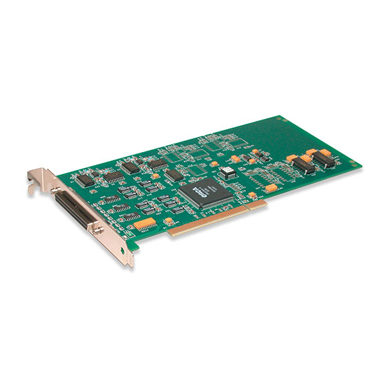
Chapter 1 Features The DT330 Series is a family of low-cost, analog output and digital I/O boards for the PCI bus. The DT330 Series consists of the following boards: DT331, DT332, DT333, DT334, and DT335. These board types differ in the number of analog output channels and... -
Page 13: Supported Software
• DT330 Series Device Driver − This software is included on the Data Acquisition OMNI CD that is shipped with the board. You must load this device driver to use a DT330 Series board with any of the supported software packages or utilities. Refer to the DT330 Series Getting Started Manual (UM-17414) for more information on loading the device driver. - Page 14 DT-Open Layers standard. • DTx-EZ − Order this optional software package if you want to use ActiveX controls to access the capabilities of the DT330 Series boards using Microsoft Visual Basic or Visual C++; DTx-EZ complies with the DT-Open Layers standard.
-
Page 15: Accessories
I/O signals provided by the DT330 Series boards. • EP305 cable − A 2-meter, twisted-pair, shielded cable that connects the 68-pin connector (J1) on the DT330 Series boards to the J1 connector on the STP68 or STP68-DIN screw terminal... - Page 16 Chapter 1...
-
Page 17: Chapter 2: Principles Of Operation
Principles of Operation Analog Output Features ........Digital I/O Features. - Page 18 Chapter 2 This chapter describes the analog output and digital I/O features of the DT330 Series boards. To frame the discussions, refer to the block diagrams shown in Figure 1. Note that bold entries indicate signals you can access. DIO Port D...
-
Page 19: Analog Output Features
Principles of Operation Analog Output Features This section describes the following analog output features of the DT331, DT332, DT333, and DT334 boards: • Resolution, • Analog output channels, • Ranges and gains, • Conversion mode, and • Data format. Resolution Table 2 lists the output resolutions supported by the DT331, DT332, DT333, and DT334 boards. -
Page 20: Analog Output Channels
±10 V (the default), 0 to 10 V, ±5 V, or 0 to 5 V. The DT333 and DT334 boards support the ±10 V range only. Specify the range using software. The gain for the D/A subsystem on the DT330 Series boards is always 1 (the default value). -
Page 21: Conversion Mode
• LSB is the least significant bit. • FSR is the full-scale range. For the DT330 Series, the full-scale analog output range is 5 for the unipolar range of 0 to 5 V, 10 for the unipolar range of 0 to 10 V or the bipolar output range of ±5 V, or 20 for the bipolar range or ±10 V. - Page 22 Chapter 2 • Offset is the minus full-scale value. The minus full-scale value is 0.0 V for the unipolar ranges, −5 V for the ±5 V range, or −10 V for the ±10 V range. For example, assume that you are using a DT331 board with a unipolar output range of 0 to 5 V.
-
Page 23: Digital I/O Features
• Interrupts, and • Operation modes. Digital I/O Lines DT330 Series boards support 32 digital I/O lines through the digital input (DIN) and output (DOUT) subsystems; the DIN and DOUT subsystems use the same digital I/O lines. These lines are divided into four ports of eight: Port A, lines 0 to 7;... -
Page 24: Resolution
Chapter 2 Resolution Using software, specify the number of digital I/O lines to read or write at once by specifying the resolution as 8, 16, 24, or 32. Choosing a resolution greater than 8 effectively combines the digital I/O ports. Table 3 shows the effect of resolution on the number of digital I/O lines available for each DIN or DOUT subsystem. -
Page 25: Interrupts
I/O lines 0 to 7 of Port D are represented as bits 24 to 31 of the digital value. Interrupts When using 8-bit resolution only, the DT330 Series boards can generate a PCI-bus interrupt when any of the eight digital I/O lines corresponding to digital Port D (DIN element 3) changes state. This... - Page 26 Chapter 2 Note: Although single-value operations are the simplest to use, they do not allow you to check the interrupt status. • Continuous digital input operations − Allow you to read digital input values and check the interrupt status of digital Port D only. Use software to specify DIN subsystem element 3, continuous mode, a resolution of 8, the trigger source as software, and the window or procedure to handle the messages.
-
Page 27: Chapter 3: Supported Device Driver Capabilities
Supported Device Driver Capabilities... - Page 28 Chapter 3 The DT330 Series Device Driver provides support for D/A, DIN, and DOUT subsystems. For information on how to install the device driver, refer to the DT330 Series Getting Started Manual. Table 1 summarizes the board features available for use with the DataAcq SDK.
- Page 29 Supported Device Driver Capabilities Table 4: DT330 Series Supported Options DT330 Series DIN DOUT SRL C/T Total Subsystems on Board Single-Value Operation Support OLSSC_SUP_SINGLEVALUE Yes Yes Continuous Operation Support OLSSC_SUP_CONTINUOUS Continuous Operation until Trigger Event Support OLSSC_SUP_CONTINUOUS_PRETRI Continuous Operation before and after...
- Page 30 Chapter 3 Table 4: DT330 Series Supported Options (cont.) DT330 Series DIN DOUT SRL C/T Total Subsystems on Board Buffer Support OLSSC_SUP_BUFFERING Single Buffer Wrap Mode Support OLSSC_SUP_WRPSINGLE Multiple Buffer Wrap Mode Support OLSSC_SUP_WRPMULTIPLE Inprocess Buffer Flush Support OLSSC_SUP_INPROCESSFLUSH Number of DMA Channels...
- Page 31 Supported Device Driver Capabilities Table 4: DT330 Series Supported Options (cont.) DT330 Series DIN DOUT SRL C/T Total Subsystems on Board Supports Scan per Trigger Event Triggered Scan OLSSC_SUP_RETRIGGER_SCAN_ PER_TRIGGER Supports Internal Retriggered Triggered Scan OLSSC_SUP_RETRIGGER_INTERNAL Extra Retrigger Support OLSSC_SUP_RETRIGGER_EXTRA...
- Page 32 Chapter 3 Table 4: DT330 Series Supported Options (cont.) DT330 Series DIN DOUT SRL C/T Total Subsystems on Board Programmable Gain Support OLSSC_SUP_PROGRAMGAIN Number of Gains OLSSC_NUMGAINS AutoRanging Support OLSSC_SINGLEVALUE_AUTORANGE Synchronous Digital I/O Support OLSSC_SUP_SYNCHRONOUS_ DIGITALIO Maximum Synchronous Digital I/O Value...
- Page 33 Supported Device Driver Capabilities Table 4: DT330 Series Supported Options (cont.) DT330 Series DIN DOUT SRL C/T Total Subsystems on Board Filter/Channel Support OLSSC_SUP_FILTERPERCHAN Number of Filters OLSSC_NUMFILTERS Number of Voltage Ranges OLSSC_NUMRANGES Range per Channel Support OLSSC_SUP_RANGEPERCHANNEL Software Programmable Resolution...
- Page 34 Chapter 3 Table 4: DT330 Series Supported Options (cont.) DT330 Series DIN DOUT SRL C/T Total Subsystems on Board Analog Event Trigger Support OLSSC_SUP_ANALOGEVENTTRIG Digital Event Trigger Support OLSSC_SUP_DIGITALEVENTTRIG Timer Event Trigger Support OLSSC_SUP_TIMEREVENTTRIG Number of Extra Triggers OLSSC_NUMEXTRATRIGGERS Internal Clock Support...
- Page 35 Supported Device Driver Capabilities Table 4: DT330 Series Supported Options (cont.) DT330 Series DIN DOUT SRL C/T Total Subsystems on Board Cascading Support OLSSC_SUP_CASCADING Event Count Mode Support OLSC_SUP_CTMODE_COUNT Generate Rate Mode Support OLSSC_SUP_CTMODE_RATE One-Shot Mode Support OLSSC_SUP_CTMODE_ONESHOT Repetitive One-Shot Mode Support...
- Page 36 Chapter 3 Table 4: DT330 Series Supported Options (cont.) DT330 Series DIN DOUT SRL C/T Total Subsystems on Board High Level Gate Type with Input Debounce Support OLSSC_SUP_GATE_HIGH_LEVEL_ DEBOUNCE Low Level Gate Type with Input Debounce Support OLSSC_SUP_GATE_LOW_LEVEL_ DEBOUNCE High Edge Gate Type with Input...
- Page 37 Supported Device Driver Capabilities Table 4: DT330 Series Supported Options (cont.) DT330 Series DIN DOUT SRL C/T Total Subsystems on Board Data Processing Capability OLSSC_SUP_PROCESSOR Software Calibration Support OLSSC_SUP_SWCAL a. The DT335 board contains no D/A subsystems. b. DIN and DOUT subsystems use the same DIO lines.
- Page 38 Chapter 3...
-
Page 39: Chapter 4: Programming Flowcharts
Programming Flowcharts Single-Value Operations ....... . . Continuous Digital Input Operations ..... . - Page 40 Chapter 4 The following flowcharts show the steps required to perform data acquisition operations using DT-Open Layers. For illustration purposes, the DataAcq SDK functions are shown; however, the concepts apply to all DT-Open Layers software. Note that many steps represent several substeps; if you are unfamiliar with the detailed operations involved with any one step, refer to the indicated page for detailed information.
-
Page 41: Single-Value Operations
Programming Flowcharts Single-Value Operations Initialize the device driver and get the device handle with olDaInitialize. Specify D/A for an analog output subsystem, Get a handle to the subsystem with DIN for a digital input subsystem, or DOUT for a digital output subsystem. olDaGetDASS. - Page 42 Chapter 4 Single-Value Operations (cont.) Continued from previous page. Acquire a single value using Acquiring olDaGetSingleValue. data? Acquire/ Output a single value using output olDaPutSingleValue. another value? Release the subsystem using olDaReleaseDASS. Release the driver and terminate the session using olDaTerminate.
-
Page 43: Continuous Digital Input Operations
Programming Flowcharts Continuous Digital Input Operations Initialize the device driver and get the device handle with olDaInitialize. Get a handle to the DIN subsystem element 3 with olDaGetDASS. Set the data flow to OL_DF_CONTINUOUS using olDaSetDataFlow. Set the resolution with Specify a resolution of 8 for DIN subsystem 3. - Page 44 Chapter 4 Continuous Digital Input Operations (cont.) Continued from previous page. Start the operation with olDaStart. The event done message is OLDA_WM_EVENT_DONE. In olDaSetWndHandle or olDaSetNotificationProcedure, the subsystem handle, HDASS, is returned in the wParam parameter; this allows one window to handle messages from all subsystems.The subsystem status is returned in the IParam parameter.
- Page 45 Programming Flowcharts Set Subsystem Parameters Specify the channel type using Specify the channel type as differential (the default). olDaSetChannelType. For DIN and DOUT subsystems only, specify the resolution as 8, 16, 24, or 32. If the resolution is 8 (the default), four digital I/O subsystems (elements 0 to 3) Specify the resolution using are available (one for each port).
- Page 46 Chapter 4 Stop the Operation The driver posts at Stop in an Stop the operation in an least one buffer done orderly orderly way using olDaStop. and queue stopped way? message. Stop the operation Reinitialize? olDaAbort and immediately and reinitialize the olDaReset stop subsystem using olDaReset.
- Page 47 Programming Flowcharts Clean up the Operation Release the subsystem using olDaReleaseDASS. Release the driver and terminate the session using olDaTerminate.
- Page 48 Chapter 4...
-
Page 49: Chapter 5: Calibration
Connecting an External Meter ......Calibrating a DT330 Series Board ...... - Page 50 Note: Ensure that you installed the DT330 Series Device Driver and the DT330 Series Support Software prior to using the DT330 Series Calibration Utility.
-
Page 51: Running The Calibration Utility
DT330 Series Getting Started Manual. Locate the Data Translation, Inc./DT330 Series program group on your hard disk. This program group was created when you installed the DT330 Series Support Software. Double-click the DT330 Series Calibration Utility icon. -
Page 52: Connecting An External Meter
Chapter 5 Connecting an External Meter To calibrate the analog output circuitry, use an external precision meter available from vendors such as Fluke. Connect each DAC as follows: Connect the positive side of the analog output channel to the positive side of the precision voltage meter. (Refer to Table 2 screw terminal assignments.) Connect the return side of the analog output channel to the... -
Page 53: Calibrating A Dt330 Series Board
Calibration Calibrating a DT330 Series Board Once the DT330 Series Calibration Utility is running and you have connected the required calibration signals to the STP68 or STP68-DIN screw terminal panel, perform the following steps to calibrate the analog output subsystem of the DT331, DT332, DT333, or DT334... - Page 54 Chapter 5...
-
Page 55: Chapter 6: Troubleshooting
Troubleshooting General Checklist ........Service and Support . -
Page 56: General Checklist
DT330 Series Getting Started Manual. Check that you have installed and configured the device driver properly using the instructions in the DT330 Series Getting Started Manual. Search the DT Knowledgebase in the Support section of the Data Translation web site (at www.datatranslation.com) for an answer... - Page 57 Series board is located is a PCI slot and that a PCI expansion slot. the board is correctly seated in the slot; see the instructions in the DT330 Series Getting Started Manual. The board is Contact Data Translation for technical damaged.
- Page 58 (cont.) interrupts. If you still have an interrupt (cont.) conflict, remove the network device, install the DT330 Series board, and reboot the system. Then, reinsert the network device. Intermittent Loose connections or Check your wiring and tighten any loose operation.
- Page 59 Series board is located is a PCI slot, that the board is correctly seated in the slot, and that the board is secured in the slot with a screw; see the instructions in the DT330 Series Getting Started Manual. The power supply of...
- Page 60 Some network devices do not share interrupts. If you still have an interrupt conflict, remove the network device, install the DT330 Series board, and reboot the system. Then, reinsert the network device. Test button Vdtdad VxD is not...
-
Page 61: Service And Support
Refer to the Data Translation Support Policy located at the end of this manual for a list of services included and excluded in our standard support offering. - Page 62 If you are located outside the USA, call your local distributor. The name and telephone number of you nearest distributor are provided in your Data Translation catalog. If you are leaving a message to request a support call, please include the following information: •...
- Page 63 Address: _________________________________________________________________________ ________________________________________________________________________________ Data Translation hardware product(s): __________________________________________________ serial number: _________________________________________________________________ configuration: _________________________________________________________________ Data Translation device driver - SPO number: ___________ ________________________________ _______________________________________________ version: _________________________ Data Translation software - SPO number:_______________ ________________________________ serial number: ________________________________ version:__________________________ PC make/model: ___________________________________________________________________ operating system: _____________________________ version:__________________________...
-
Page 64: E-Mail And Fax Support
Chapter 6 E-Mail and Fax Support You can also get technical support by e-mailing or faxing the Technical Support Department: • E-mail: You can reach Technical Support at the following address: tsupport@datx.com Ensure that you provide the following minimum information: −... -
Page 65: If Your Board Needs Factory Service
Troubleshooting If Your Board Needs Factory Service If your board must be returned to Data Translation, perform the following steps: Record the board’s serial number, then contact the Customer Service Department at (508) 481-3700 (if you are in the USA) and obtain a Return Material Authorization (RMA). - Page 66 Chapter 6...
-
Page 67: Appendix A: Specifications
Specifications... - Page 68 Appendix A Table 4 lists the specifications for the D/A subsystem on the DT331, DT332, DT333, and DT334 boards. Table 4: D/A Subsystem Specifications Feature Specifications Number of analog output channels DT331: DT332: DT333: DT334: Resolution DT331, DT332: 12 bits DT333, DT334: 16 bits Data encoding (input)
- Page 69 Settling time to 0.01% of FSR 10.0 µs, 100 mV step Slew rate 2 V/µs Table 5 lists the specifications for the DIN/DOUT subsystems on all DT330 Series boards. Table 5: DIN/DOUT Subsystem Specifications Ports A, B, and C Port D Feature Specifications...
- Page 70 The minimum pulse width applies only to interrupt-on-change detection. Pulses less than the minimum may not be detected as a change. Table 6 lists the power, physical, and environmental specifications for the DT330 Series boards. Table 6: Power, Physical, and Environmental Specifications Feature Specifications Power +5 V (±0.25 V):...
- Page 71 Specifications Table 7 lists the specifications for the 68-pin connector on the board. Table 7: 68-Pin Connector Specifications Feature Specifications Connector part number: AMP 68-pin, 0.05 Subminiature D, #749621-7 Shielded enclosure with jack AMP 750752-1 screws: Recommended shielded cable: Madison, 28 GA, Twisted Pair, #68KDK00029...
- Page 72 Appendix A...
-
Page 73: Appendix B: Connector Pin Assignments
Connector Pin Assignments... - Page 74 Appendix B Table 8 lists the pin assignments of connector J1 on the DT330 Series boards. Table 8: Connector J1 Pin Assignments on the DT330 Series Board Number Signal Description Number Signal Description +5 V Output No Connect Digital Ground...
- Page 75 Connector Pin Assignments Table 8: Connector J1 Pin Assignments on the DT330 Series Board (cont.) Number Signal Description Number Signal Description Digital I/O Port D, Line 0 Digital Ground Digital I/O Port C, Line 6 Digital I/O Port C, Line 4...
- Page 76 Appendix B Table 9 lists the screw terminal assignments for the STP68 or STP68-DIN screw terminal panel. Table 9: Screw Terminal Assignments for the STP68 or STP68-DIN Screw Terminal Panel Pin # Signal Description Pin # Signal Description +5 V Output No Connect Digital Ground Digital I/O Port D, Line 7...
- Page 77 Connector Pin Assignments Table 9: Screw Terminal Assignments for the STP68 or STP68-DIN Screw Terminal Panel (cont.) Pin # Signal Description Pin # Signal Description Digital I/O Port D, Line 0 Digital Ground Digital I/O Port C, Line 6 Digital I/O Port C, Line 4 Digital I/O Port C, Line 2 Digital I/O Port C, Line 0 Digital Ground...
- Page 78 Appendix B...
-
Page 79: Index
Index channels analog output aborting an operation digital I/O accessories number of Agilent VEE clocks analog output features base frequency calibrating maximum external clock divider channels maximum throughput conversion modes minimum external clock divider data format minimum throughput gain number of extra output ranges connecting an external meter resolution... - Page 80 DIN subsystem interrupts specifications IParam DOUT subsystem specifications DT VPI DT330 Series Device Driver J1 connector pin assignments DT-LV Link DT330 Series board DTx-EZ STP-68 panel e-mail support LabVIEW environmental specifications lines, digital I/O EP305 cable...
- Page 81 Index I/O channels olDaSetEncoding resolutions olDaSetNotificationProcedure scans per trigger olDaSetRange single-ended channels olDaSetResolution voltage ranges olDaSetTrigger olDaSetWndHandle olDaStart olDaStop OLDA_WM_EVENT_DONE olDaTerminate olDaAbort in continuous digital input olDaConfig operations in continuous digital input in single-value operations operations OLSSC_CGLDEPTH in single-value operations OLSSC_MAX_DIGITALIOLIST_ olDaGetDASS VALUE...
- Page 82 DT330 Series J1 connector connector STP-68 panel J1 connector digital I/O ports environmental power specifications physical programmable resolution power...
- Page 83 Index technical support e-mail telephone World-Wide Web telephone support Testpoint throughput maximum minimum triggers number of extra software troubleshooting procedure service and support procedure troubleshooting table Visual Basic programs Visual C++ programs Windows messages World-Wide Web writing programs in C/C++ writing programs in Visual Basic writing programs in Visual C++...
- Page 84 Index...
- Page 85 CUSTOMER SERVICE POLICY charge, any defective component part of such products. a. Data Translation, Inc. will repair or replace, at its option, any faulty item within ten days after receipt EFFECTIVE PERIOD OF WARRANTY of said part regardless of its warranty status.
- Page 87 (b) telephone support for support upon the following terms and conditions at problem determination, verification and resolution prices published by Data Translation from time to (or instruction as to work-around, as applicable) on a time. Current price information is available from call-back basis during Data Translation's normal Data Translation, or its authorized distributor.
- Page 88 Data Translation's by either party upon thirty (30) days prior written then current rates (Specialized Application Support notice to the other party.
- Page 89 Data Translation. Pursuant to Section 2.4 of the Agreement, the Support Fee will also be adjusted in accordance with Data Translation's then current fee schedule as additional Licensed Processors are added. Support Fees do not include travel and living...
Need help?
Do you have a question about the DT330 Series and is the answer not in the manual?
Questions and answers