Table of Contents
Advertisement
Quick Links
Advertisement
Table of Contents

Related Manuals for Data Translation DT330 Series


Summary of Contents for Data Translation DT330 Series
- Page 1 UM-17414-C DT330 Series Getting Started Manual...
- Page 2 Third Edition Copyright © 1999, 2000 by Data Translation, December, 2000 Inc. All rights reserved. No part of this publication may be reproduced, stored in a retrieval system, or transmitted, in any form by any means, electronic, mechanical, by photocopying, recording, or otherwise, without the prior written permission of Data Translation, Inc.
-
Page 3: Table Of Contents
DT330 Series Key Hardware Features ..... . . DT330 Series Software ........ - Page 4 Connecting Digital Output Signals ......Chapter 5: Verifying the Operation of a DT330 Series Board ......... . .
-
Page 5: About This Manual
Intended Audience This document is intended for engineers, scientists, technicians, or others responsible for setting up a DT330 Series board to perform data acquisition operations. It is assumed that you are familiar with the requirements of your application. It is also assumed that you are ... -
Page 6: Conventions Used In This Manual
About this Manual • Chapter “Installing the Board and Loading the Device Driver,” describes how to install the DT330 Series board, attach the STP68 or STP68-DIN screw terminal panel to the board, and load the DT330 Series Device Driver. •... -
Page 7: Related Information
Related Information Refer to the following documents for more information on using the DT330 Series board: • The DT330 Series User’s Manual (UM-17416). Included on the Data Acquisition OMNI CD provided with the DT330 Series board, this manual describes the features of the DT330 Series boards and the DT330 Series Device Driver in detail. -
Page 8: Where To Get Help
About this Manual Where To Get Help Should you run into problems installing or using a DT330 Series board, our Technical Support Department is available to provide technical assistance. Refer to the DT330 Series User’s Manual for more information (refer to... -
Page 9: Chapter 1: Overview
DT330 Series Key Hardware Features ..... . . DT330 Series Software ........ -
Page 10: Dt330 Series Key Hardware Features
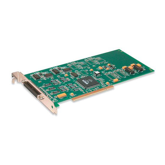
Chapter 1 DT330 Series Key Hardware Features The DT330 Series is a family of low-cost, analog output and digital I/O boards for the PCI bus. The DT330 Series consists of the following boards: DT331, DT332, DT333, and DT334. The key features... -
Page 11: Dt330 Series Software
• The Quick Data Acq application − This application provides a quick way to get a DT330 Series board up and running. Using the Quick Data Acq application, you can verify the features of the board, display data on the screen, and save data to disk. -
Page 12: Getting Started Procedure
The flow diagram shown in Figure 1 illustrates the steps needed to get started using a DT330 Series board. This diagram is repeated in each chapter; the shaded area in the diagram shows you where you are in the getting started procedure. -
Page 13: Chapter 2: Preparing To Use A Dt330 Series Board
Installing the Software ........Viewing the DT330 Series Documentation Online ... - Page 14 Chapter 2 Prepare to Use a Board (this chapter) Install the Board and Load the Device Driver (see Chapter 3 starting on page Wire Signals (see Chapter 4 starting on page Verify the Operation of the Board (see Chapter 5 starting on page 37...
-
Page 15: Unpacking
• DT330 Series data acquisition board, and • Data Acquisition OMNI CD. If an item is missing or damaged, contact Data Translation. If you are in the United States, call the Customer Service Department at (508) 481-3700. An application engineer will guide you through the appropriate steps for replacing missing or damaged items. -
Page 16: Checking The System Requirements
Chapter 2 Checking the System Requirements For reliable operation, your DT330 Series board requires the following minimum system requirements: • An 80486, Pentium, or compatible processor; • At least one available PCI (revision 2.0-compliant or greater), 32-bit or 64-bit, +5 V expansion slot;... -
Page 17: Installing The Software
WDM-compliant device drivers and DLLs (version 5.0 or greater) for the DT330 Series boards. Other Data Translation boards/modules may not provide WDM-compliant drivers. You cannot use a DT330 Series board at the same time as another Data Translation board/module unless both devices provide WDM-compliant drivers. - Page 18 Chapter 2 10. Either change the program folder name or accept the default program folder name, then click Next. The files are copied to the destination directory. 11. Click Finish. The DT Data Acquisition Software setup program reappears. 12. Click Main Menu. 13.
-
Page 19: Viewing The Dt330 Series Documentation Online
Preparing to Use a DT330 Series Board Viewing the DT330 Series Documentation Online Once you have installed the DT330 Series Software, you can view the DT330 Series documentation by clicking the manual title. You can access the manuals from the Data Translation, Inc\DT330 Series program group. - Page 20 Chapter 2...
-
Page 21: Device Driver
Setting up an Expansion Slot ......Inserting the DT330 Series Board into the Computer .. - Page 22 (see Chapter 5 starting on page 37 Note: All DT330 Series boards are factory-calibrated and require no further adjustment prior to installation. If you are using the DT330 Series board and decide later to recalibrate it, refer to the DT330 Series User’s Manual for instructions (see...
-
Page 23: Setting Up The Computer
Installing the Board and Loading the Device Driver Setting up the Computer CAUTION: To prevent electrostatic damage that can occur when handling electronic equipment, use a ground strap or similar device when performing this installation procedure. To set up the computer, perform the following steps: Turn off the computer. -
Page 24: Setting Up An Expansion Slot
Chapter 3 Setting up an Expansion Slot Once you have set up the computer, set up an expansion slot by performing the following steps: Select a 32-bit or 64-bit PCI expansion slot. PCI slots are shorter than ISA or EISA slots and are usually white or ivory. -
Page 25: Inserting The Dt330 Series Board Into The Computer
Position the board so that the cable connectors are facing the rear of the computer, as shown in Figure Rear of Computer DT330 Series Board PCI Expansion Slot Bus Connector Figure 2: Inserting the DT330 Series Board in the Computer... - Page 26 Power up the computer. If you installed the DT330 Series software (as described on page 9), the DT330 Series device driver is automatically loaded. If you have not installed the software, ensure that you do now.
-
Page 27: Attaching A Stp68 Or Stp68-Din Screw Terminal Panel
To attach the STP68 or STP68-DIN screw terminal panel to the DT330 Series board, you need the EP305 or equivalent cable. The STP68, STP68-DIN, and the EP305 are offered by Data Translation as accessories to the DT330 Series boards. Connector J1 on the STP68 and STP68-DIN attaches to connector J1 on the DT330 Series board. -
Page 28: Loading The Device Driver
Chapter 3 Loading the Device Driver To load the DT330 Series device driver in Windows 98, follow the steps in the next section. To load the DT330 Series device driver in Windows Me, follow the steps on page 21. To load the DT330 Series device driver in Windows NT 4.0, follow the steps on... -
Page 29: Windows Me
Windows Me In Windows Me, the driver is automatically loaded when you install the DT330 Series driver from the Data Acquisition OMNI CD. To configure the device driver, perform the following steps: Open the Control Panel. -
Page 30: Windows Nt 4.0
Chapter 3 Windows NT 4.0 In Windows NT 4.0, the driver is automatically loaded when you install the DT330 Series driver from the Data Acquisition OMNI CD. To configure the device driver, perform the following steps: Open the Control Panel. - Page 31 Open the Control Panel. Double-click the Open Layers Control Panel icon. 10. Select the DT330 Series board to configure, then click Advanced. 11. Select the appropriate boxes to enable interrupts for lines (bits) 0 to 7 on digital port D.
- Page 32 Chapter 3...
-
Page 33: Chapter 4: Wiring Signals
Wiring Signals Before Wiring ......... . Connecting Analog Output Signals. - Page 34 Chapter 4 Prepare to Use a Board (see Chapter 2 starting on page Install the Board and Load the Device Driver (see Chapter 3 starting on page Wire Signals (this chapter) Verify the Operation of the Board (see Chapter 5 starting on page 37...
-
Page 35: Before Wiring
STP68 or STP68-DIN screw terminal panel: • Use individually shielded twisted-pair wire (size 14 to 26 AWG) when using the DT330 Series board in a highly noisy electrical environment. • Separate power and signal lines by using physically different wiring paths or conduits. -
Page 36: Stp68 And Stp68-Din Screw Terminal Assignments
Chapter 4 − If you have not done so already, install the DT330 Series software. − Run the Quick Data Acq application (described in Chapter 5 starting on page 37) to verify that the board is operating properly. − Once you have determined that the board is operating properly, wire the signals according to your application’s... - Page 37 Wiring Signals J1, 68-Pin Connector Figure 4: Layout of the STP68 or STP68-DIN Screw Terminal Panel Connector J1 on the screw terminal panel brings out all of the signals from 68-pin connector on the data acquisition board. The following sections describe the screw terminal assignments on the STP68 or STP68-DIN screw terminal panel by function.
-
Page 38: Analog Output And Power Screw Terminals
Chapter 4 Analog Output and Power Screw Terminals Table 2 lists the screw terminal assignments for analog output and power connections on the STP68 or STP68-DIN screw terminal panel. The +5 V output signal (TB1) is provided for low current signal conditioning applications up to 1 A. -
Page 39: Digital I/O Screw Terminals
Wiring Signals Digital I/O Screw Terminals Table 3 lists the screw terminal assignments for digital I/O connections on the STP68 or STP68-DIN screw terminal panel. Table 3: Digital I/O Screw Terminal Assignments on the STP68 or STP68-DIN J1 Pin J1 Pin Description Description Digital Ground... - Page 40 Chapter 4 Table 3: Digital I/O Screw Terminal Assignments on the STP68 or STP68-DIN (cont.) J1 Pin J1 Pin Description Description Digital I/O Port D, Line 4 Digital I/O Port D, Line 5 Digital I/O Port D, Line 6 Digital I/O Port D, Line 7 Digital Ground Digital Ground...
-
Page 41: Connecting Analog Output Signals
Wiring Signals Connecting Analog Output Signals Figure 5 shows how to connect an analog output voltage signal (channel 0, in this case) to the STP68 or STP68-DIN screw terminal panel. STP68 or STP68-DIN Screw Terminal Panel Analog Output 0 TB28 Load TB27 Analog Output 0... -
Page 42: Connecting Digital Input Signals
Chapter 4 Connecting Digital Input Signals Figure 6 shows how to connect a digital input signal (lines 4 and 6 of digital Port A, in this case) to the STP68 or STP68-DIN screw terminal panel. Digital Ground TB52 Digital I/O Port A, Line 6 TB53 Digital I/O Port A, Line 4 TB54... -
Page 43: Connecting Digital Output Signals
Wiring Signals Connecting Digital Output Signals Figure 7 shows how to connect a digital output signal (line 0 of digital Port B, in this case) to the STP68or STP68-DIN screw terminal panel. STP68 or STP68-DIN Screw Terminal Panel 0 Out = LED On TB51 Digital I/O Port B, Line 0 Ω... - Page 44 Chapter 4...
-
Page 45: Chapter 5: Verifying The Operation Of A Dt330 Series Board
Verifying the Operation of a DT330 Series Board Installing the Quick Data Acq Application ....Running the Quick Data Acq Application .... - Page 46 Chapter 4 starting on page Verify the Operation of the Board (this chapter) You can verify the operation of a DT330 Series board using the Quick Data Acq application. Quick Data Acq allows you to perform the following operations: • Acquire data from a single digital input port; and •...
-
Page 47: Installing The Quick Data Acq Application
Verifying the Operation of a DT330 Series Board Installing the Quick Data Acq Application To install the Quick Data Acq application, perform the following steps: Insert the Data Acquisition OMNI CD into your CD-ROM drive. Click Start from the Task Bar, then click Run. - Page 48 Chapter 5 13. Click Main Menu. 14. Click Exit.
-
Page 49: Running The Quick Data Acq Application
Verifying the Operation of a DT330 Series Board Running the Quick Data Acq Application To run the Quick Data Acq application, perform the following steps: If you have not already done so, power up your computer and any attached peripherals. -
Page 50: Performing A Single Value Analog Output Operation
Click the Control menu. Click Single Analog Output. Select the appropriate DT330 Series board from the Board list box. In the Channel list box, select analog output channel 0. In the Range list box, select the output range of DAC0. -
Page 51: Performing A Single Value Digital Output Operation
Click the Control menu. Click Digital Output. Select the appropriate DT330 Series board from the Board list box. Select digital output port B by clicking Port B. Click the appropriate bits to select the digital output lines to write to. - Page 52 Chapter 5...
-
Page 53: Appendix A: Using Your Own Screw Terminal Panel
Using Your Own Screw Terminal Panel Analog Outputs ........Digital Inputs . - Page 54 This appendix describes additional considerations to keep in mind when designing your own screw terminal panel for use with a DT330 Series board. Refer to Appendix B of the DT330 Series User’s Manual (see page 11 for information on viewing this manual) for connector and cable specifications.
-
Page 55: Analog Outputs
Using Your Own Screw Terminal Panel Analog Outputs The analog output channels on DT330 Series boards have a resolution of 12 or 16 bits (even though the accuracy may be less). Data Translation ensures that the analog outputs do not break into a high frequency oscillation with high capacitance loads that may be experienced with long cables. -
Page 56: Digital Inputs
Appendix A Digital Inputs TTL-type inputs must have current limiting so that circuitry is not damaged when power is removed. On all Data Translation PCI boards, current limiting is used to prevent damage in this fault condition. On high-speed clock inputs, a ground that is located in the connector next to the clock must be connected as a twisted pair with the high-speed clock input. -
Page 57: Digital Outputs
Using Your Own Screw Terminal Panel Digital Outputs If you are using the high drive capability of any of the PCI boards, ensure that the load is returned to the digital ground provided in the connector next to the outputs. If just eight of the digital outputs are switching 16 mA per output, then 128 mA of current flows. - Page 58 Appendix A...
-
Page 59: Index
Windows NT 4.0 analog outputs digital inputs digital outputs conventions used manuals device driver online help digital I/O screw terminal assignments when not using the STP68 or STP68-DIN power, screw terminal assignments wiring inputs DT330 Series Device Driver expansion slot selection... - Page 60 Index Quick Data Acq Windows 2000, loading the device installing driver running Windows 98, loading the device driver single value analog output operations Windows Me, loading the device single value digital input operations driver Windows NT 4.0, loading the device single value digital output operations driver wiring recommendations...
Need help?
Do you have a question about the DT330 Series and is the answer not in the manual?
Questions and answers