Table of Contents
Advertisement
Quick Links
Advertisement
Table of Contents

Related Manuals for Data Translation DT300 Series


Summary of Contents for Data Translation DT300 Series
- Page 1 UM-16503-E DT300 Series Getting Started Manual...
- Page 2 Data Translation, Inc. Information furnished by Data Translation, Inc. is believed to be accurate and reliable; however, no responsibility is assumed by Data Translation, Inc. for its use; nor for any infringements of patents or other rights of third parties which may result from its use.
-
Page 3: Table Of Contents
Chapter 1: Overview ....... . DT300 Series Software ........ - Page 4 Contents Chapter 4: Attaching and Configuring a Screw Terminal Panel/Backplane ........Using an STP300 Screw Terminal Panel .
- Page 5 Connecting Pulse Output Signals ..... . Chapter 6: Verifying the Operation of a DT300 Series Board ......... . .
- Page 6 Contents...
-
Page 7: About This Manual
Intended Audience This document is intended for engineers, scientists, technicians, or others responsible for setting up a DT300 Series board to perform data acquisition operations. It is assumed that you are familiar with the requirements of your application. It is also assumed that you are ... - Page 8 DT300 Series software, and view the DT300 Series documentation online. • Chapter “Installing the Board and Loading the Device Driver,” describes how to install the DT300 Series board and load the DT300 Series device driver. • Chapter “Attaching and Configuring a Screw Terminal Panel/Backplane,”...
-
Page 9: Related Information
Related Information Refer to the following documents for more information on using the DT300 Series board: • The DT300 Series User’s Manual (UM-16501). Included on the Data Acquisition OMNI CD provided with the DT300 Series board, this manual describes the features of the DT300 Series boards and the DT300 Series Device Driver in detail. -
Page 10: Where To Get Help
About this Manual Where To Get Help Should you run into problems installing or using a DT300 Series board, our Technical Support Department is available to provide technical assistance. Refer to the DT300 Series User’s Manual for more information (refer to... -
Page 11: Chapter 1: Overview
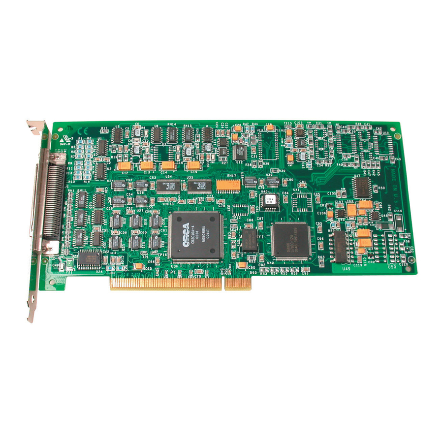
Overview DT300 Series Software ........ - Page 12 DT300 Series Key Hardware Features The DT300 Series is a family of low-cost, multifunction data acquisition boards for the PCI bus. The DT300 Series consists of the following boards: DT301, DT302, DT303, DT304, DT321, and DT322. The key features of these boards are listed in...
-
Page 13: Dt300 Series Software
• The Quick Data Acq application − This application provides a quick way to get a DT300 Series board up and running. Using the Quick Data Acq application, you can verify the features of the board, display data on the screen, and save data to disk. -
Page 14: Getting Started Procedure
The flow diagram shown in Figure 1 illustrates the steps needed to get started using a DT300 Series board. This diagram is repeated in each chapter; the shaded area in the diagram shows you where you are in the getting started procedure. -
Page 15: Chapter 2: Preparing To Use A Dt300 Series Board
Installing the Software........Viewing the DT300 Series Documentation Online ... - Page 16 Chapter 2 Prepare to Use a Board (this chapter) Install the Board and Load the Device Driver (see Chapter 3 starting on page Attach and Configure the Screw Terminal Panel and Signal Conditioning Backplane (see Chapter 4 starting on page Wire Signals (see Chapter 5 starting on page...
-
Page 17: Unpacking
• DT300 Series data acquisition board, and • Data Acquisition OMNI CD. If an item is missing or damaged, contact Data Translation. If you are in the United States, call the Customer Service Department at (508) 481-3700. An application engineer will guide you through the appropriate steps for replacing missing or damaged items. -
Page 18: Checking The System Requirements
Chapter 2 Checking the System Requirements For reliable operation, your DT300 Series board requires the following minimum system requirements: • An 80486, Pentium, or compatible processor; • At least one available PCI (revision 2.0-compliant or greater), 32-bit or 64-bit, +5 V expansion slot;... -
Page 19: Installing The Software
WDM-compliant device drivers and DLLs (version 5.0 or greater). Other Data Translation boards/modules may not provide WDM-compliant drivers. You cannot use a DT300 Series board at the same time as another Data Translation board/module unless both devices provide WDM-compliant drivers. - Page 20 Chapter 2 Select DT300 Series, then click Next. You are prompted for the program folder name. 10. Either change the program folder name or accept the default program folder name, then click Next. The files are copied to the destination directory.
-
Page 21: Viewing The Dt300 Series Documentation Online
Preparing to Use a DT300 Series Board Viewing the DT300 Series Documentation Online Once you have installed the DT300 Series Software, you can view the DT300 Series documentation by clicking the manual title. You can access the manuals from the Data Translation, Inc\DT300 Series program group. - Page 22 Chapter 2...
-
Page 23: Device Driver
Installing the Board and Loading the Device Driver Setting up the Computer ....... . . Setting up an Expansion Slot . - Page 24 Verify the Operation of the Board (see Chapter 6 starting on page Note: All DT300 Series boards are factory-calibrated and require no further adjustment prior to installation. If you are using the DT300 Series board and decide later to recalibrate it, refer to the DT300 Series User’s Manual for instructions (see...
-
Page 25: Setting Up The Computer
Installing the Board and Loading the Device Driver Setting up the Computer CAUTION: To prevent electrostatic damage that can occur when handling electronic equipment, use a ground strap or similar device when performing this installation procedure. To set up the computer, perform the following steps: Turn off the computer. -
Page 26: Setting Up An Expansion Slot
Chapter 3 Setting up an Expansion Slot Once you have set up the computer, set up an expansion slot by performing the following steps: Select a 32-bit or 64-bit PCI expansion slot. PCI slots are shorter than ISA or EISA slots and are usually white or ivory. - Page 27 Position the board so that the cable connectors are facing the rear of the computer, as shown in Figure Rear of Computer DT300 Series Board PCI Expansion Slot Bus Connector Figure 2: Inserting the DT300 Series Board in the Computer...
- Page 28 Power up the computer. If you installed the DT300 Series software (as described on page 9), the DT300 Series device driver is automatically loaded. If you have not installed the software, ensure that you do now.
-
Page 29: Loading The Device Driver
Installing the Board and Loading the Device Driver Loading the Device Driver To load the DT300 Series device driver in Windows 98, follow the steps in the next section. To load the DT300 Series device driver in Windows Me, follow the steps on page 20. -
Page 30: Windows Me
Windows Me In Windows Me, the driver is automatically loaded when you install the DT300 Series driver from the Data Acquisition OMNI CD. To configure the device driver, perform the following steps: Open the Control Panel. Double-click the Open Layers Control Panel icon. -
Page 31: Windows 2000
Windows 2000 Once you have installed the DT300 Series driver from the Data Acquisition OMNI CD, installed a DT300 Series board, and powered up the host computer, the New Hardware Found dialog box appears. - Page 32 Chapter 3 Once the driver is loaded, perform the steps in Chapter 4 to attach and configure the screw terminal panel and signal conditioning backplane.
-
Page 33: Chapter 4: Attaching And Configuring A Screw Terminal Panel/Backplane
Attaching and Configuring a Screw Terminal Panel/ Backplane Using an STP300 Screw Terminal Panel ....Using an STP68 or STP68-DIN Screw Terminal Panel ..Using a 5B01 or 5B08 Signal Conditioning Backplane . - Page 34 Chapter 4 Prepare to Use a Board (see Chapter 2 starting on page Install the Board and Load the Device Driver (see Chapter 3 starting on page Attach and Configure a Screw Terminal Panel and Signal Conditioning Backplane (this chapter) Wire Signals (see Chapter 5 starting on page...
-
Page 35: Using An Stp300 Screw Terminal Panel
Using an STP300 Screw Terminal Panel This section describes how to attach an STP300 screw terminal panel to a DT300 Series board and how to configure a STP300 screw terminal panel for use with a DT300 Series board. Attaching an STP300 Screw Terminal Panel To attach an STP300 screw terminal panel to the DT300 Series board, you need the EP305 or equivalent cable. -
Page 36: Configuring An Stp300 Screw Terminal Panel
Chapter 4 Configuring an STP300 Screw Terminal Panel Figure 4 shows the layout of the STP300 screw terminal panel. J1, 68-Pin Connector Counter/Timers R8 to R1 Spare Jumpers R16 to R8 Counter/Timers Clk & Trig Pwr Gnd +5 V Analog Inputs Digital I/O Analog Outputs Gnd Amp Low Digital I/O... -
Page 37: Configuring Jumpers On The Stp300
Configuring Jumper W1 - Common Ground Sense When shipped from the factory, jumper W1 connects the low side of the input amplifier (Amp Low) on the DT300 Series board to analog ground. When using pseudo-differential analog inputs, remove jumper W1 and connect Amp Low to a remote common-mode voltage to reject offset voltages common to all 16 input channels. -
Page 38: Configuring Jumpers W4 To W7 - Analog Outputs
5B01 signal conditioning backplane. Install jumpers W4 and W5 to connect DAC0 from the DT300 Series board to channel 14 on the 5B01 backplane. Jumper W4 connects DAC0 to channel 14; jumper W5 connects DAC0’s return. -
Page 39: Configuring Resistors On The Stp300
Attaching and Configuring a Screw Terminal Panel/ Backplane Configuring Resistors on the STP300 Locations are provided on the STP300 screw terminal panel for installing bias return and current shunt resistors. The following subsections describe how to configure these resistors. Configuring Resistors R1 to R8 - Bias Return Resistor locations R1 to R8 connect the low side of analog input channels to analog ground. -
Page 40: Using An Stp68 Or Stp68-Din Screw Terminal Panel
To attach the STP68 or STP68-DIN screw terminal panel to the DT300 Series board, you need the EP305 or equivalent cable. The STP68, STP68-DIN, and the EP305 are offered by Data Translation as accessories to the DT300 Series boards. Connector J1 on the STP68 and STP68-DIN attaches to connector J1 on the DT300 Series board. -
Page 41: Using A 5B01 Or 5B08 Signal Conditioning Backplane
This section describes how to attach a 5B01 or 5B08 signal conditioning backplane to an STP300 screw terminal panel and how to configure the backplane for use with a DT300 Series board. Attaching a 5B01 or 5B08 Backplane If you want to condition your analog signals, you can attach a 5B01 or 5B08 signal conditioning backplane to the STP300 using the AC1315 cable. -
Page 42: Configuring A 5B01 Or 5B08 Backplane
5B Series modules, keep the following considerations in mind: • Configure your DT300 Series board to use single-ended mode. • The 5B08 maps to single-ended analog input channels 0 to 7. Therefore, if you are using a 5B08 with the STP300 screw terminal... - Page 43 For example, if you are using 5B modules that have an output of ±5 V, use an input range of ±5 V on the DT300 Series board. • Connect all unused inputs to analog common. Reading an open channel can cause settling problems on the next valid channel.
- Page 44 Chapter 4...
-
Page 45: Chapter 5: Wiring Signals
Wiring Signals Before Wiring ......... . Connecting Analog Input Signals . - Page 46 For information on how to wire signals to the 5B01 or 5B08 signal conditioning backplanes, refer to the 5B Series User’s Guide. Note: For information on the pin assignments of the STP68 and STP68-DIN screw terminal panels, refer to the DT300 Series User’s Manual.
-
Page 47: Before Wiring
Keep the following recommendations in mind when wiring signals to the STP300 screw terminal panel: • Use individually shielded twisted-pair wire (size 14 to 26 AWG) when using the DT300 Series board in a highly noisy electrical environment. • Separate power and signal lines by using physically different wiring paths or conduits. -
Page 48: Stp300 Screw Terminal Assignments
Chapter 5 − If you have not done so already, install the DT300 Series software. − Run the Quick Data Acq application (described in Chapter 6 starting on page 65) to verify that the board is operating properly. − Once you have determined that the board is operating properly, wire the signals according to your application’s... -
Page 49: Analog Input Screw Terminals
Wiring Signals Analog Input Screw Terminals Table 2 lists the screw terminal (TB) assignments for analog input connections on the STP300 screw terminal panel. The corresponding resistors and their use are also listed. Table 2: Analog Input Screw Terminal Assignments on the STP300 Resistor Use Bias Return Current Shunt... - Page 50 Chapter 5 Table 2: Analog Input Screw Terminal Assignments on the STP300 (cont.) Resistor Use Bias Return Current Shunt TB # J1 Pin # Description Resistor Resistor − Analog Input 6 Analog Input 14/ Analog Input 6 Return − Analog Input 7 Analog Input 15/ Analog Input 7 Return Amp Low...
-
Page 51: Analog Output And Power Screw Terminals
Wiring Signals Analog Output and Power Screw Terminals Table 3 lists the screw terminal (TB) assignments for analog output and power connections on the STP300 screw terminal panel. Table 3: Analog Output and Power Screw Terminal Assignments on the STP300 TB # J1 Pin # Description... -
Page 52: Counter/Timer And Digital I/O Screw Terminals
Chapter 5 Counter/Timer and Digital I/O Screw Terminals Table 4 lists the screw terminal (TB) assignments for digital I/O connections on the STP300 screw terminal panel. Table 4: Counter/Timer and Digital I/O Screw Terminal Assignments on the STP300 J1 Pin J1 Pin Description Description... - Page 53 Wiring Signals Table 4: Counter/Timer and Digital I/O Screw Terminal Assignments on the STP300 (cont.) J1 Pin J1 Pin Description Description External Gate 2 Digital I/O Port B, Line 4 Digital Ground Digital I/O Port B, Line 5 User Clock Input 3 Digital I/O Port B, Line 6 User Counter Output 3...
- Page 54 Chapter 5 Note: If you are connecting a high-speed clock to the STP300, it is recommended that you connect the return to the adjacent ground screw terminal.
-
Page 55: Connecting Analog Input Signals
Wiring Signals Connecting Analog Input Signals The STP300 screw terminal panel supports both voltage and current loop inputs. You can connect analog input voltage signals to the STP300 in the following configurations: • Single-ended − Choose this configuration when you want to measure high-level signals, when noise is not significant, when the source of the input is close to the STP300 screw terminal panel, and when all the input signals are referred to the same... -
Page 56: Connecting Single-Ended Voltage Inputs
Chapter 5 Connecting Single-Ended Voltage Inputs Figure 7 shows how to connect single-ended voltage inputs (channels 0, 1, and 8, in this case) to the STP300 screw terminal panel. STP300 Panel Jumper W1 Signal Installed Source TB17 (Amp Low) TB18 Analog In 0 source Analog In 8... -
Page 57: Connecting Pseudo-Differential Voltage Inputs
Wiring Signals Connecting Pseudo-Differential Voltage Inputs Figure 8 shows how to connect pseudo-differential voltage inputs (channels 0, 1, and 8, in this case) to the STP300 screw terminal panel. Signal Source TB17 source Analog In 0 TB18 Analog In 8 STP300 Analog In 1 Panel... -
Page 58: Connecting Differential Voltage Inputs
Chapter 5 Connecting Differential Voltage Inputs Figure 9A illustrates how to connect a floating signal source to the STP300 screw terminal panel using differential inputs. (A floating signal source is a voltage source that has no connection with earth ground.) You need to provide a bias return path by adding resistors R1 to R8 for channels 0 to 7, respectively, for floating signal sources. - Page 59 Wiring Signals STP300 Panel Analog In 0 TB18 Floating Signal Analog In 0 Source Return You can use resistor R1 to Analog Ground connect the low side of channel 0 to analog ground. STP300 Panel Bridge Analog In 0 TB18 Analog In 0 Return DC Supply...
- Page 60 Chapter 5 Note that since they measure the difference between the signals at the high (+) and low (−) inputs, differential connections usually cancel any common-mode voltages, leaving only the signal. However, if you are using a grounded signal source and ground loop problems arise, connect the differential signals to the STP300 screw terminal panel as shown in Figure...
-
Page 61: Connecting Current Loop Inputs
Wiring Signals Connecting Current Loop Inputs Figure 11 shows how to connect a current loop input (channel 0, in this case) to the STP300 screw terminal panel. STP300 Panel 4 to 20 mA Analog Input 0 TB18 Analog Input 0 Return Analog Ground Use current shunt resistor R9 to convert current to... -
Page 62: Connecting Analog Output Signals
Chapter 5 Connecting Analog Output Signals Figure 12 shows how to connect an analog output voltage signal (channel 0, in this case) to the STP300 screw terminal panel using an external +10 V reference. Analog Output 0 TB19 Analog Output 0 Return Load TB20 Analog Output 0 Reference... - Page 63 Wiring Signals DT300 Series Board STP300 Panel Analog Output 0 TB19 Analog Output 0 Return Load TB20 DAC0 TB21 Ω 10 k +10 V Reference Figure 13: Connecting Analog Output Voltages Using the Board’s Internal +10 V Reference (Shown for Channel 0)
-
Page 64: Connecting Digital I/O Signals
Chapter 5 Connecting Digital I/O Signals Figure 14 shows how to connect digital input signals (lines 0 and 1 of digital Port A, in this case) to the STP300 screw terminal panel. STP300 Panel Digital I/O Port A, Line 0 TB49 TB50 TTL Inputs... - Page 65 Wiring Signals STP300 Panel 0 Out = LED On TB57 Ω Digital I/O Port B, Line 0 Digital Ground TB43 Figure 15: Connecting Digital Outputs (Shown for Channel 0, Port B)
-
Page 66: Connecting Counter/Timer Signals
• Frequency measurement, and • Pulse output (rate generation, one-shot, and repetitive one-shot). This section describes how to connect counter/timer signals to perform these operations. Refer to the DT300 Series User’s Manual for more information on using the counter/timers (refer to Chapter 6 starting on page 65 for information on viewing this document). - Page 67 Wiring Signals STP300 Panel Digital Ground TB25 TB26 User Clock Input 0 TB28 Signal Source Gate 0 TB29 External Gating Switch Digital Ground Figure 16: Connecting Event Counting Signals (Shown for Clock Input 0 and External Gate 0) Figure 17 shows another example of connecting event counting signals to the STP300 screw terminal panel using user counter 0.
- Page 68 Chapter 5 STP300 Panel Digital Ground TB25 TB26 Signal Source User Clock Input 0 Figure 17: Connecting Event Counting Signals without an External Gate Input (Shown for Clock Input 0) Figure 18 shows an example of how to cascade two counters externally to perform an event counting operation using user counters 0 and 1.
- Page 69 Wiring Signals STP300 Panel User Digital Ground TB25 Counter TB26 Output 0 TB27 Gate 0 TB28 Signal Source TB29 User Clock Input 0 TB30 User Clock Gate 1 Input 1 TB32 External Gating Switch* Digital Ground Ω * An internal 22 k pull-up resistor to +5 V is used.
-
Page 70: Connecting Frequency Measurement Signals
Chapter 5 Connecting Frequency Measurement Signals This section describes two examples of how to connect frequency measurement signals to the STP300 screw terminal panel. The first configuration uses the same wiring as an event counting application that does not use an external gate signal (see Figure 17 page 58);... -
Page 71: Connecting Pulse Output Signals
Wiring Signals Connecting Pulse Output Signals Figure 20 shows one example of connecting pulse output signals to the STP300 screw terminal panel using user counter 0. STP300 Panel Digital Ground TB25 TB27 TB28 Heater TB29 Controller User Counter Output 0 External Gate 0 Gating... - Page 72 Chapter 5 STP300 Panel User Digital Ground TB25 Counter TB26 Output 0 TB27 TB28 Signal Source TB29 User Clock Input 0 TB30 User Clock Input 1 External Gating Switch Gate 0 Digital Ground Figure 21: Cascading Counters (Shown for Rate Generation Using Counters 0 and 1 and External Gate 0) Figure 22 shows an example of how to cascade two counters...
- Page 73 Wiring Signals STP300 Panel User Digital Ground TB25 Counter TB26 Output 0 TB27 Signal Source User Clock Input 0 TB29 TB30 User Clock Input 1 TB32 Digital Ground One-Shot Trigger Gate 1 Figure 22: Cascading Counters (Shown for One-Shot Using Counters 0 and 1 and External Gate 1)
- Page 74 Chapter 5...
-
Page 75: Chapter 6: Verifying The Operation Of A Dt300 Series Board
Verifying the Operation of a DT300 Series Board Installing the Quick Data Acq Application ....Running the Quick Data Acq Application .... - Page 76 Chapter 5 starting on page Verify the Operation of the Board (this chapter) You can verify the operation of a DT300 Series board using the Quick Data Acq application. Quick Data Acq allows you to perform the following operations: • Acquire data from a single analog input channel or digital input port;...
-
Page 77: Installing The Quick Data Acq Application
Verifying the Operation of a DT300 Series Board Installing the Quick Data Acq Application To install the Quick Data Acq application, perform the following steps: Insert the Data Acquisition OMNI CD into your CD-ROM drive. Click Start from the Task Bar, then click Run. - Page 78 Chapter 6 13. Click Main Menu. 14. Click Exit.
-
Page 79: Running The Quick Data Acq Application
Verifying the Operation of a DT300 Series Board Running the Quick Data Acq Application To run the Quick Data Acq application, perform the following steps: If you have not already done so, power up your computer and any attached peripherals. -
Page 80: Performing A Single Value Analog Input Operation
To verify that the board can read a single analog input value, perform the following steps: Connect a voltage source, such as a function generator, to analog input channel 0 (differential mode) on the DT300 Series board. Refer to page 49 for an example of how to connect a differential analog input. -
Page 81: Performing A Continuous Analog Input Operation
To verify that the board can perform a continuous analog input operation, perform the following steps: Connect known voltage sources, such as the outputs of a function generator, to analog input channels 0 and 1 on the DT300 Series board (using the differential configuration). Refer to page 49 an example of how to connect a differential analog input. -
Page 82: Performing A Single Value Digital Input Operation
DT300 Series board. Refer to page 54 for an example of how to connect a digital input. Click the Acquisition menu. Click Digital Input. Select the appropriate DT300 Series board from the Board list box. Select digital input port A by clicking Port A. -
Page 83: Performing A Single Value Digital Output Operation
Click the Control menu. Click Digital Output. Select the appropriate DT300 Series board from the Board list box. Select digital output port B by clicking Port B. Click the appropriate bits to select the digital output lines to write to. -
Page 84: Performing A Frequency Measurement Operation
Note: The Quick Data Acq application works only with counter/timer 0. Click the Acquisition menu. Click Frequency Counter. Select the appropriate DT300 Series board from the Board list box. In the Count Duration text box, enter the number of seconds during which events will be counted. -
Page 85: Performing A Pulse Output Operation
Performing a Pulse Output Operation To verify that the board can perform a pulse output operation, perform the following steps: Connect a scope to counter/timer 0 on the DT300 Series board. Refer to page 61 for an example of how to connect a scope (a pulse output) to counter/timer 0. - Page 86 Chapter 6...
-
Page 87: Appendix A: Using Your Own Screw Terminal Panel
Using Your Own Screw Terminal Panel Analog Inputs ......... . Analog Outputs . - Page 88 This appendix describes additional considerations to keep in mind when designing your own screw terminal panel for use with a DT300 Series board. Refer to Appendix B of the DT300 Series User’s Manual on the OMNI CD-ROM (see page 11 for information on viewing this manual) for connector and cable specifications.
-
Page 89: Analog Inputs
Using Your Own Screw Terminal Panel Analog Inputs DT300 Series boards have three different types of analog input configurations that you can use: • Single-ended, • Pseudo-differential, and • Differential. Single-Ended Inputs With single-ended inputs, you have the maximum number of inputs but have the worst-case noise immunity without external signal conditioning. -
Page 90: Pseudo-Differential Inputs
Appendix A Pseudo-Differential Inputs Pseudo-differential inputs allow one common-mode voltage for all single-ended inputs. With this type of connection, the low side of the instrumentation amplifier is used to sense an external common-mode voltage. For example, if you have a signal-conditioning rack, the AMP LOW signal connects to the analog common of the external rack. - Page 91 Using Your Own Screw Terminal Panel With a very small bias current multiplied by this high input impedance, the voltage produced is out of the common-mode input range of the instrumentation amplifier. An external resistor must be provided to return this bias current to the analog common of the data acquisition board.
-
Page 92: Analog Outputs
Appendix A Analog Outputs The analog output channels on DT300 Series boards have a resolution of 12 or 16 bits (even though the accuracy may be less). Data Translation ensures that the analog outputs do not break into a high frequency oscillation with high capacitance loads that may be experienced with long cables. -
Page 93: Digital Inputs And Counter/Timer Inputs
Using Your Own Screw Terminal Panel Digital Inputs and Counter/Timer Inputs TTL-type inputs must have current limiting so that circuitry is not damaged when power is removed. On all Data Translation PCI boards, current limiting is used to prevent damage in this fault condition. -
Page 94: Digital Outputs
Appendix A Digital Outputs If you are using the high drive capability of any of the PCI boards, ensure that the load is returned to the digital ground provided in the connector next to the outputs. If just eight of the digital outputs are switching 16 mA per output, then 128 mA of current flows. -
Page 95: Index
Index Numerics externally cascaded counter/timers 5B01 backplane frequency measurement applications attaching configuring for analog outputs pseudo-differential analog inputs considerations when using pulse output applications 5B08 backplane single-ended analog inputs attaching attaching the screw terminal panel considerations when using cable AC1315 cable AC1315 analog input EP305... - Page 96 Windows NT 4.0 wiring digital inputs, when not using the STP300 digital outputs, when not using the manuals STP300 DT300 Series Device Driver online help EP305 cable event counting expansion slot selection power, screw terminal assignments pseudo-differential inputs help, online...
- Page 97 Index power resistors R1 to R8 Quick Data Acq resistors R9 to R16 continuous analog input operations selecting an expansion slot setting up the computer frequency measurement operations single-ended inputs slot selection installing software supported pulse output operations system requirements running single value analog input operations single value analog output...
- Page 98 Index externally cascading counter/timers frequency measurement applications pseudo-differential analog inputs pulse output applications single-ended analog inputs...
Need help?
Do you have a question about the DT300 Series and is the answer not in the manual?
Questions and answers