
Related Manuals for Photon Focus MV0 3D06 Series


Summary of Contents for Photon Focus MV0 3D06 Series
- Page 1 Photonfocus MV0 CMOSIS 3D06 Camera Series CMOS camera series with GigE Interface MV0-D2048x1088-C01-3D06-768-G2 MV0-D2048-C01-3D06-768-G2 MAN083 08/2020 V1.2...
- Page 2 All information provided in this manual is believed to be accurate and reliable. No responsibility is assumed by Photonfocus AG for its use. Photonfocus AG reserves the right to make changes to this information without notice. Reproduction of this manual in whole or in part, by any means, is prohibited without prior permission having been obtained from Photonfocus AG.
-
Page 3: Table Of Contents
Contents 1 Preface 1.1 IMPORTANT NOTICE! ........1.2 About Photonfocus . - Page 4 CONTENTS 4.4.2 Exposure Start Trigger ....... . 30 4.4.3 Exposure End Trigger ....... . . 30 4.4.4 Exposure Control Output Signals .
- Page 5 CONTENTS 11 Frame Rate 11.1 Exposure time is dominant ........61 11.2 Image size is dominant and limited by the interface .
- Page 6 CONTENTS 15.6.2 Encoder Interface ........100 15.6.3 Single-ended Line Input .
- Page 7 CONTENTS C.3.3 Real Time Counter ........127 C.3.4 Missed Trigger Counter .
- Page 8 CONTENTS MAN083 08/2020 V1.2 8 of 129...
-
Page 9: Preface
Preface 1.1 IMPORTANT NOTICE! READ THE INSTRUCTIONS FOR USE BEFORE OPERATING THE CAMERA STORE THE INSTRUCTIONS FOR USE FOR FURTHER READING Photonfocus AG Bahnhofplatz 10 CH-8853 Lachen SZ Switzerland www.photonfocus.com info@photonfocus.com +41 – 55 451 00 00 MAN083 08/2020 V1.2 9 of 129... -
Page 10: About Photonfocus
1 Preface 1.2 About Photonfocus The Swiss company Photonfocus is one of the leading specialists in the development of CMOS image sensors and corresponding industrial cameras for machine vision. Photonfocus is dedicated to making the latest generation of CMOS technology commercially available. -
Page 11: Legend
1.6 Legend Photonfocus can not be held responsible for any technical or typographical er- rors. 1.6 Legend In this documentation the reader’s attention is drawn to the following icons: Important note, additional information Important instructions General warning, possible component damage hazard Warning, electric shock hazard Warning, fire hazard MAN083 08/2020 V1.2... - Page 12 1 Preface MAN083 08/2020 V1.2 12 of 129...
-
Page 13: Introduction
Introduction 2.1 Introduction This manual describes standard Photonfocus MV0 CMOSIS series cameras that have a Gigbit Ethernet (GigE) interface. The cameras contain CMV2000 and CMV4000 from CMOSIS. 2.2 Camera Naming Convention The naming convention of the MV0 CMOSIS camera series is summarized in Fig. 2.1. S e n s o r P r e f i x 2 I n t e r f a c e t y p e... - Page 14 2 Introduction Name Max Resolution Max Frame Rate Notes MV0-D2048x1088-C01-3D06-768-G2 2048 x 1088 18540 fps Gigabit Ethernet 2 MP monochrome standard camera. MV0-D2048-C01-3D06-768-G2 2048 x 2048 14842 fps Gigabit Ethernet 4 MP monochrome standard camera. Table 2.1: Camera models covered by this manual (Footnotes: frame rate in 3Donly mode @ 2048 x 11 resolution) MAN083 08/2020 V1.2...
-
Page 15: Product Specification 3.1 Introduction
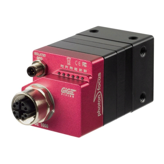
Product Specification 3.1 Introduction The Photonfocus MV0 CMOSIS GigE camera series is built around the CMOS image sensors CMV2000 and CMV4000 from CMOSIS. They provide a resolution of 2048x1088 (CMV2000) and 2048x2048 (CMV4000) pixels. The camera series is optimized for low light conditions. The cameras are aimed at standard applications in industrial image processing where high sensitivity and high frame rates are required. - Page 16 3 Product Specification L a s e r C a m e r a + o n v e y o r b e l t w i t h o b j e c t s Figure 3.1: Triangulation principle with objects moved on a conveyor belt Figure 3.2: Photonfocus MV0 CMOSIS GigE camera series MAN083 08/2020 V1.2 16 of 129...
-
Page 17: Feature Overview
3.2 Feature Overview 3.2 Feature Overview The general specification and features of the camera are listed in the following sections. The detailed description of the camera features is given in the following chapters. Characteristics Photonfocus MV0 CMOSIS GigE Camera Series Interface Gigabit Ethernet (PoE), GigE Vision and GenICam compliant Camera Control... -
Page 18: Technical Specification
3 Product Specification 3.3 Technical Specification 2 MPix Cameras 4 MPix Cameras Sensor Manufacturer CMOSIS Sensor Type CMV2000 CMV4000 Technology CMOS active pixel Scanning system progressive scan Optical format / diagonal 2/3” (12.75 mm diagonal) 1" (15.92 mm diagonal) Resolution 2048x1088 pixels 2048x1088 pixels Pixel size... -
Page 19: Absolute Maximum Ratings
3.3 Technical Specification Photonfocus MV0 CMOSIS GigE Camera Series Operating temperature / moisture 0°C ... 50°C / 20 ... 80 % (camera needs to be connected to heat sink) Storage temperature / moisture -25°C ... 60°C / 20 ... 95 % Trigger signal input range +5 .. - Page 20 3 Product Specification Parameter Value Camera Control Input Single Ended +5 V ... +20 V Table 3.5: Electrical Characteristics Monochrome 1000 Wavelength [nm] Figure 3.3: Quantum efficiency (QE) [%] of the CMV2000/4000 monochrome and near infrared image sensors (with micro lenses) MAN083 08/2020 V1.2 20 of 129...
-
Page 21: Image Acquisition
Image Acquisition This chapter gives detailed information about the controlling of the image acquisition. It shows how the camera can be triggered or run in free-running mode, and how the frame rate can be configured. The structure offers a lot of flexibility in the configuration. It follows the GenI- Cam naming convention. -
Page 22: Image Acquisition, Frame And Exposure Control Parameters
4 Image Acquisition Acquisition Control The acquisition control block takes care of the acquisition function. The camera can only capture frames, when the acquisition has been started and is active (see Section 4.2 for more information). Frame Control The frame control block takes care of the capturing of one or many frames and burst of frames (see Section 4.3 for more information). -
Page 23: Image Acquisition, Frame And Exposure Trigger
4.1 Overview This list shows only an overview of available parameters. The function and usage of them are explained in the following chapters. 4.1.4 Image Acquisition, Frame and Exposure Trigger The camera can run in "free-running" mode, which means that it captures images automatically in full frame rate once the acquisition has been started. -
Page 24: Acquisition Control
4 Image Acquisition 4.2 Acquisition Control A c q u i s i t i o n T r i g g e r W a i t ) c q u i s i t i o n C o n t r o l A c q u i s i t i o n A c t i v e A c q u i s i t i o n S t a r t T r i g g e r ) c q u i s i t i o n S t a r t ( ) -
Page 25: Acquisition Start Trigger
4.2 Acquisition Control ) c q u i s i t i o n S t a r t ( ) A c q u i s i t i o n S t o p ( ) . r a m e F r a m e . -
Page 26: Acquisition End Trigger
4 Image Acquisition 4.2.4 Acquisition End Trigger The acquisition end trigger can be used to control the acquisition end procedure. The main property of this trigger is the trigger mode. It can be set to on or off: Acquisition End Trigger Mode = on When the acquisition status is "Acquisition Active", it goes to "Acquisition Trigger Wait"... -
Page 27: Frame Control
4.3 Frame Control 4.3 Frame Control . r a m e C o n t r o l F r a m e T r i g g e r W a i t F r a m e A c t i v e F r a m e S t a r t T r i g g e r F r a m e S t a r t F r a m e B u r s t S t a r t T r i g g e r... -
Page 28: Frame Burst End Trigger
4 Image Acquisition A c q u i s i t i o n S t a r t ( ) A c q u i s i t i o n S t o p ( ) . r a m e . -
Page 29: Frame Control Output Signals
4.3 Frame Control A c q u i s i t i o n S t a r t ( ) A c q u i s i t i o n S t o p ( ) . r a m e . -
Page 30: Exposure Control
4 Image Acquisition 4.4 Exposure Control - x p o s u r e C o n t r o l E x p o s u r e A c t i v e E x p o s u r e S t a r t T r i g g e r E x p o s u r e S t a r t E x p o s u r e E n d T r i g g e r E x p o s u r e E n d... -
Page 31: Exposure Control Output Signals
4.4 Exposure Control Exposure End Trigger Mode = on An activated exposure cycle will be terminated and the image read out will be started, as soon as an exposure end trigger has been received. The "Exposure Active" status goes to inactive. Exposure end triggers are only processed, when an exposure start trigger has started a trigger controlled exposure cycle previously. -
Page 32: Overlapped Image Acquisition Timing
4 Image Acquisition 4.5 Overlapped Image Acquisition Timing The camera is able to perform an overlapped image acquisition. It means, a new exposure can be started during the image readout of the previous image. Fig. 4.10 shows an image acquisition procedure when images are captured in overlapped mode. The status "Frame Active"... - Page 33 4.5 Overlapped Image Acquisition Timing which can be counted by a counter (see Section 5.1.5 for more information how to count missed triggers). Fig. 4.11 and Fig. 4.12 shows both timing situations, when the exposure time longer than the read out time and when the exposure time is shorter than the read out time. F r a m e - x p o s u r e R e a d O u t...
-
Page 34: Acquisition-, Frame- And Exposure-Trigger Configuration
4 Image Acquisition 4.6 Acquisition-, Frame- and Exposure-Trigger Configuration The acquisition-, frame- and exposure timing can be controlled by 7 triggers: • Acquisition Start Trigger • Acquisition End Trigger • Frame Start Trigger • Frame Burst Start Trigger • Frame Burst End Trigger •... -
Page 35: Trigger Software
4.6 Acquisition-, Frame- and Exposure-Trigger Configuration Software Signal Pulse A trigger is generated by the software signal pulse, which comes from a common software signal pulse register (see Section 4.7 for more information). Counter Start A trigger signal is generated by the counter start event (see Section 5.1.3 for more information about the counter start event). -
Page 36: Trigger Divider
4 Image Acquisition 4.6.5 Trigger Divider The trigger divider specifies a division factor of the incoming trigger pulses. A division factor of 1 processes every incoming trigger. A division factor of 2 processes every second trigger and so 4.6.6 Trigger Delay The trigger delay lets the user specify a delay, that will be applied between the reception of a trigger event and when the trigger becomes active. -
Page 37: Software Signal Pulse And User Output
4.7 Software Signal Pulse and User Output 4.7 Software Signal Pulse and User Output The software signal pulse block contains eight general purpose registers which allow generating internal pulse signals by software access. These pulse signals are internally connected to following functions, where it can be used to start a procedure: •... - Page 38 4 Image Acquisition MAN083 08/2020 V1.2 38 of 129...
-
Page 39: Counter & Timer
Counter & Timer 5.1 Counter + o u n t e r A c t i v a t i o n C o u n t e r 4 i s i n g E d g e T r i g g e r F a l l i n g E d g e B o t h... -
Page 40: Counter Status
5 Counter & Timer If additionally a trigger source is selected, the counter is waiting for a trigger. It ignores counter events until a valid trigger event has been received. A valid trigger signal on the selected trigger source starts the counter, which means, that it counts the predefined number of events from the start value according to the counter start value and duration configuration. -
Page 41: Counter Event Source
5.1 Counter Counter Trigger Source Off The state of the counter changes to "trigger wait". The counter reset source can be set to the counter end signal of the same counter. This allows to restart the counter automatically as soon as it arrives its end condition. -
Page 42: Counter Trigger Source
5 Counter & Timer MissedFrameBurstStartTrigger Count the number of missed frame burst start triggers. A missed frame burst start trigger event is generated, when a frame burst start trigger cannot be processed. MissedExposureStartTrigger Count the number of missed exposure start triggers. A missed exposure start trigger event is generated, when an exposure start trigger cannot be processed. -
Page 43: Counter Reset Source
5.1 Counter Exposure Start Starts with the reception of the exposure start event. Exposure End Starts with the reception of the exposure end event. User Output 0 ... 7 Starts and counts events as long as the selected user output bit is asserted. When the counter is started, it ignores counter events as long as the corresponding user output bit is deasserted (see Section 4.7). - Page 44 5 Counter & Timer Acquisition End Resets with the reception of the acquisition end event. FrameTrigger Resets with the reception of the frame trigger. Frame Start Resets with the reception of the frame start event. Frame End Resets with the reception of the frame end event. Frame Burst Start Resets with the reception of the frame burst start event.
-
Page 45: Timer
5.2 Timer 6 i m e r T i m e r R e s e t ( ) T i m e r S t a t u s T i m e r A c t i v e A c t i v a t i o n T i m e r 6 i m e r V a l u e... -
Page 46: Timer Active, -Start And -End Signal
5 Counter & Timer 5.2.3 Timer Active, -Start and -End Signal Timer Active An asserted timer active signal indicates, that the timer has started counting the configured duration period. The timer active signal is internally routed to the I/O control block and can there be selected for output on the physical output line or on one of the available leds. - Page 47 5.2 Timer Action 0 ... 3 Starts with the reception of the chosen action signal event. Software Signal Pulse 0 ... 7 Starts with the reception of chosen software signal pulse event (see Section 4.7). Line Input Starts when the specified counter trigger activation condition is met on the chosen line.
- Page 48 5 Counter & Timer MAN083 08/2020 V1.2 48 of 129...
-
Page 49: Encoder
Encoder - n c o d e r E n c o d e r S o u r c e A E n c o d e r R e s e t ( ) E n c o d e r S t a t u s E n c o d e r T r i g g e r E n c o d e r E n c o d e r V a l u e... -
Page 50: Encoder Trigger Output
6 Encoder G r a y C o u n t e r H i g h R e s o l u t i o n C o u n t e r F o u r P h a s e C o u n t e r Figure 6.2: Encoder Modes 6.2 Encoder trigger output The trigger output of the encoder reacts to changes of the position counter. -
Page 51: Encoder Reset Source
6.4 Encoder Reset Source Encoder Idle Encoder is idle, either no trigger sources are configured or the encoder is waiting on the reset. Encoder Up The position counter last incremented. Encoder Down The position counter last decremented. Encoder Static The position counter hasn’t changed in the EncoderTimeout period. The encoder also switches to this state when it is reset while in the idle state. - Page 52 6 Encoder Rising Edge Encoder starts with the rising edge on the selected line input. Falling Edge Encoder starts with the falling edge on the selected line input Both Edges Encoder starts with any edge on the selected line input Level High Resets the encoder as long as the level is high.
-
Page 53: O Control
I/O Control This chapter shows the structure of the physical input and physical output line. It describes the signal path and how to configure it. The I/O control block contains a signal input path and a signal output path. 7.1 Input Signal Path The camera has two physical signal input lines, which come from the input opto-isolator of the camera hardware interface (see Section 15.6) and which is fed into the input signal path of the camera. -
Page 54: Output Signal Path
7 I/O Control 7.2 Output Signal Path The camera has one physical signal output line and three LEDs (S0, S1 & S2), which can be configured according to the need of the application. The physical output line is connected to the output opto-isolator in the camera hardware interface (see Section 15.6). -
Page 55: Action Control
Action Control ) c t i o n C o n t r o l A c t i o n U n c o n d i t i o n a l M o d e ) c t i o n D e v i c e K e y A c t i o n 3 A c t i o n 2 A c t i o n 3... -
Page 56: Action Control Output
8 Action Control 8.2 Action Control Output The action output signals can be used to trigger other blocks, like counter, timer, acquisition, frame or exposure control. MAN083 08/2020 V1.2 56 of 129... -
Page 57: User Storage
User Storage Photonfocus Cameras provide the user with access to an internal storage that can be used for example for calibration purposes. This can be especially useful for example for 3D applications, or any 2D applications that require calibration on a per-camera basis. The storage can be accessed in two different ways: through the UserStorage_Address1B and the UserStorage_Data1B or UserStorage_Address4B and UserStorage_Data4B. - Page 58 9 User Storage MAN083 08/2020 V1.2 58 of 129...
-
Page 59: Image Format Control
Image Format Control The focus on the interesting parts of an image can be set by setting the region of interest (ROI) (see Section 10.2). The ROI influences the image size which leads into an increased frame rate (see Chapter 11 for more information about the available frame rate). - Page 60 10 Image Format Control MAN083 08/2020 V1.2 60 of 129...
-
Page 61: Frame Rate
Frame Rate The frame rate depends on the image size, the used exposure time and the max data rate of the GigE interface (MaxDataRateInterface). The image size is given by the image size, which can be configured by the ROI, MROI and decimation settings (see Chapter 10). Two different timing situations has to be considered: •... -
Page 62: Maximum Frame Rate In 2Donly Mode
11 Frame Rate 11.4 Maximum Frame Rate in 2Donly mode A list of common used image dimension and its frame rates in 2Donly mode is shown in Table 11.1. It shows the maximum possible frame rates when the exposure time is smaller than the read out time. - Page 63 11.5 Maximum Frame Rate in 3Donly mode Peak0_3DH D2048x1088-C01 D2048x1088-C01 HS D2048-C01 D2048-C01 HS 2048 n.a. n.a. 180 fps 358 fps 1088 339 fps 672 fps 337 fps 666 fps 714 fps 1403 fps 707 fps 1377 fps 1403 fps 2714 fps 1377 fps 2619 fps...
- Page 64 11 Frame Rate MAN083 08/2020 V1.2 64 of 129...
-
Page 65: High Dynamic Range Mode (Hdr)
High Dynamic Range Mode (HDR) To have an accurate laser line detection it is important that the pixels that represent the laser line, are not saturated. The High Dynamic Range (HDR) mode is a special integration mode that increases the dynamic range of the pixels, and thus avoids the saturation of the pixels in many cases. - Page 66 12 High Dynamic Range Mode (HDR) P i x e l r e s e t V h i g h K n e e p o i n t A V l o w 2 ( M u l t i s l o p e _ V a l u e 2 ) K n e e p o i n t B V l o w 1 ( M u l t i s l o p e _ V a l u e 1 ) J i m e...
-
Page 67: Image Data Processing 13.1 Overview
Image Data Processing 13.1 Overview The pixel, which are read out of the image sensor, are processed in the cameras data path. The sequence of blocks is shown in figure Fig. 13.1. 1 m a g e S e n s o r C o l u m n F P N C o r r e c t i o n D i g i t a l O f f s e t... -
Page 68: Column Fpn Correction
13 Image Data Processing 13.2 Column FPN Correction Due to the readout structure of the image sensors there is a column-wise fixed pattern noise (FPN). The Column FPN Correction (ColCorrection) adds or subtracts a fixed value to a column. These values are obtained by a calibration process. The ColCorrection of the camera was calibrated at Photonfocus production facility. -
Page 69: Storing The Calibration In Permanent Memory
13.3 Gain and Offset Column noise changes with different analog gain settings. The column FPN cor- rection of the camera needs to be recalibrated when the analog gain setting is changed. 13.2.3 Storing the calibration in permanent memory After running the calibration procedure (see Section 13.2.2) the calibration values are stored in RAM. -
Page 70: Features
13 Image Data Processing Figure 13.2: Laser test image 13.5 3D Features 13.5.1 Overview The MV0 CMOSIS 3D06 cameras contain a very accurate laser line detector for laser triangulation (measurement of 3D profiles) that extracts 3D information in real time. For more details see Section 13.5.4. -
Page 71: Laser Line Detection
13.5 3D Features The accuracy of the triangulation system is determined by the line extracting algorithm, the optical setup, the quality parameters of the laser line generator and the parameters of the lens which makes optical engineering necessary. Triangulation Setup 1 In this setup the camera points at a viewing angle to the laser line projected from the top. - Page 72 13 Image Data Processing L i n e L a s e r + a m e r a Figure 13.4: Triangulation setup 2 + a m e r a L i n e L a s e r Figure 13.5: Triangulation setup 3 •...
- Page 73 13.5 3D Features L i n e L a s e r + a m e r a Figure 13.6: Triangulation setup 4 above the width threshold, the resulting laser line width is 0. In this case the width threshold value should be changed. Laser line height For the COG algorithm, the laser line height is the highest grey value of the detected laser line.
- Page 74 13 Image Data Processing G a u s s i a n s h a p e d l a s e r l i n e H e i g h t W i d t h T h r e s h o l d T h r e s h o l d y - d i r e c t i o n 9 i d t h...
-
Page 75: Interpolation Technique
13.5 3D Features 13.5.4 Interpolation Technique Structured light based systems crucially rely on an accurate determination of the peak position of the Gaussian shaped laser line. The LineFinder algorithm in the MV0 CMOSIS 3D06 cameras applies nonlinear interpolation techniques, where 16 data points are calculated between two pixels within the Gaussian shaped laser line. - Page 76 13 Image Data Processing ( r o t a t e d b y 9 0 ° ) I n t e r p o l a t e d r e s o l u t i o n M a x i m u m v a l u e i n t e r p o l a t i o n...
-
Page 77: Modes
13.5 3D Features 13.5.5 3D modes The camera has three modes that determine which data is transmitted to the user: 2Donly Laser detection is turned off and camera behaves as a normal area scan camera. This mode serves as a preview mode in the setup and debugging phase. 2D&3D Laser line detection is turned on. - Page 78 13 Image Data Processing B i t s ! D r o w D e s c r i p t i o n P E A K [ 1 5 : 8 ] D e t e c t e d l a s e r l i n e c o o r d i n a t e . P E A K [ 1 5 : 4 ] : i n t e g e r p a r t , P E A K [ 3 : 0 ] : f r a c t i o n a l p a r t .
-
Page 79: Transmitted Data In 2D&3D Mode
13.5 3D Features Calculation example (DataFormat3D=3): Suppose that the 3D data of image column n has the following data: 14 / 140 / 10 / 128 (see also Fig. 13.12). The position of the laser line is in this case 232.75: integer part is calculated from the 8 bits of 3D row 0 followed by the 4 MSB of 3D row 1: 0b000011101000 = 0x0e8 = dec 58. -
Page 80: Transmitted Data In 3Donly Mode
13 Image Data Processing 13.5.9 Transmitted data in 3Donly mode In 3Donly mode only the 3D data is transmitted. The FrameCombine feature (see Section 13.5.10) was added to lower the transmitted frame rate. For FrameCombine = f, the data for f images are combined into one image. -
Page 81: 10Frame Combine
13.5 3D Features 13.5.10 Frame Combine Very high frame rates that are well over 1000 fps can be achieved in 3Donly mode. Every frame (image) activates an interrupt in the GigE software which will issue a high CPU load or the frame rate can not be handled at all by an overload of interrupts. - Page 82 13 Image Data Processing FrameCombine_ForceTimeout The transmission of the combined frame is forced by writing to the FrameCombine_ForceTimeout property. When the FrameCombine is finished by a timeout, then the remaining data in the combined frame will be filled with filler data: the first two pixels of every filler row have the values 0xBB (decimal 187) and 0x44 (decimal 68).
-
Page 83: 11Peak Filter
13.5 3D Features 13.5.11 Peak Filter Peaks that are detected by the LineFinder algorithm can be filtered by applying the parameters described in this section. A filtered peak appears as all 3D data set to 0, which is the same as if no peak occurred. - Page 84 13 Image Data Processing f i l t e r e d : w i d t h t o o b i g f i l t e r e d : w i d t h t o o s m a l l W i d t h T h r e s h o l d T h r e s h o l d y - d i r e c t i o n...
-
Page 85: 12Peak Mirror
13.5 3D Features 13.5.12 Peak Mirror The property Peak_Mirror flips the peak coordinates vertically by applying the formula Peak_3DH-p-1, where Peak_3DH=height of scan area and p=detected laser position. Depending on the geometrical setup of the camera and the lasers, a bigger object height may be indicated by either a smaller or larger position. -
Page 86: Status Line And Image Information
13 Image Data Processing 13.6 Status Line and Image Information There are camera properties available that give information about the acquired images, such as integration time, ROI settings or average image value. These properties can be queried by software. Alternatively, a status line within the image data can be switched on that contains all the available image information. - Page 87 13.6 Status Line and Image Information Status bits Parameter Description STAT[31:0] CNT_0 Counter 0 Value (see Section 5.1) STAT[63:32] CNT_1 Counter 1 Value (see Section 5.1) STAT[95:64] CNT_2 Counter 2 Value (see Section 5.1) STAT[127:96] CNT_3 Counter 3 Value (see Section 5.1) STAT[159:128] ENC_POS Encoder position (Not available in this camera)
- Page 88 13 Image Data Processing Camera Model Camera Type Code MV0-D2048x1088-C01-3D06-768-G2 MV0-D2048-C01-3D06-768-G2 Table 13.3: Type codes of Photonfocus MV0 CMOSIS GigE camera series MAN083 08/2020 V1.2 88 of 129...
-
Page 89: Test Images
13.7 Test Images 13.7 Test Images Test images are generated in the camera FPGA, independent of the image sensor. They can be used to check the transmission path from the camera to the acquisition software. Independent from the configured grey level resolution, every possible grey level appears the same number of times in a test image. -
Page 90: Ramp
13 Image Data Processing 13.7.1 Ramp Depending on the configured grey level resolution, the ramp test image outputs a constant pattern with increasing grey level from the left to the right side (see Fig. 13.19). Figure 13.19: Ramp test images: 8 bit output 13.7.2 LFSR The LFSR (Linear Feedback Shift Register) test image outputs a constant pattern with a pseudo-random grey level sequence containing every possible grey level that is repeated for... -
Page 91: Troubleshooting Using The Lfsr
13.7 Test Images 13.7.3 Troubleshooting using the LFSR To control the quality of your complete imaging system enable the LFSR mode, set the camera window to 1024 x 1024 pixels (x=0 and y=0) and check the histogram. The camera window can also be set to a multiple of this resolution (e.g. - Page 92 13 Image Data Processing MAN083 08/2020 V1.2 92 of 129...
-
Page 93: Precautions
Precautions 14.1 IMPORTANT NOTICE! READ THE INSTRUCTIONS FOR USE BEFORE OPERATING THE CAMERA STORE THE INSTRUCTIONS FOR USE FOR FURTHER READING The installation of the camera in the vision system should be executed by trained and instructed employees. DANGER - Electric Shock Hazard Unapproved power supplies may cause electric shock. - Page 94 14 Precautions Incorrect plugs can damage the camera connectors. Use only the connectors specified by Photonfocus in this manual. Using plugs designed for a smaller or a larger number of pins can damage the connectors. The cameras deliver the data to the vision system over interfaces with high band- width.
- Page 95 14.1 IMPORTANT NOTICE! Cleaning of the housing To clean the surface of the camera housing: • Before cleaning disconnect the camera from camera power supply and I/O connectors. • Do not use aggressive solvents or thinners which can damage the surface, the serial number label and electronic parts.
- Page 96 14 Precautions MAN083 08/2020 V1.2 96 of 129...
-
Page 97: Hardware Interface
Hardware Interface 15.1 Absolute Maximum Ratings Parameter Value Camera Control Input Signal Voltage Single Ended 0 V ... +24 V Camera Control Output Signal Voltage Single Ended 0 V ... +24 V Camera Control Output Signal Output Current Single Ended 0.1 A Camera Control Output Signal Output Power Single Ended 0.15 W... -
Page 98: Status Indicator (Gige Cameras)
15 Hardware Interface Figure 15.1: Rear view of the GigE camera 15.5 Status Indicator (GigE cameras) Six LEDs on the back of the camera gives information about the current status of the GigE CMOS cameras. LED S0, S1 and S2 are configurable. It can be selected, which camera status information is showed by these LEDs (see Section 7.2 for the available camera status signals). -
Page 99: I/O Connector
15.6 I/O Connector 15.6 I/O Connector 15.6.1 Overview The 4-pole Binder M5 x 0.5 I/O connector contains one external single-ended line input, one external single-ended line output. The pinout of the I/O connector is described in Appendix A. A suitable trigger breakout cable for Binder 4 pole connector can be ordered from your Photonfocus dealership. -
Page 100: Encoder Interface
15 Hardware Interface 15.6.2 Encoder Interface ISO_IN0 and ISO_IN1 can be used as an A/B encoder inputs. Fig. 15.3 shows how to connect the encoder to the camera. 4 p o l . B i n d e r C a m e r a C o n n e c t o r A / B E n c o d e r... - Page 101 15.6 I/O Connector 4 p o l . B i n d e r C a m e r a C o n t r o l L o g i c C o n n e c t o r Y O U R _ V C C 1 S O _ I N C u r r e n t...
-
Page 102: Single-Ended Line Output
15 Hardware Interface 15.6.4 Single-ended Line Output ISO_OUT is a single-ended isolated output. Fig. 15.6 shows the connection from the ISO_OUT output to a TTL logic device. 4 p o l . B i n d e r C o n t r o l L o g i c C a m e r a C o n n e c t o r Y O U R _ P W R... -
Page 103: Master / Slave Camera Connection
15.6 I/O Connector 15.6.5 Master / Slave Camera Connection The trigger input of one Photonfocus MV0 GigE camera can easily connected to the strobe output of another Photonfocus G2 camera as shown in Fig. 15.9. This results in a master/slave mode where the slave camera operates synchronously to the master camera. - Page 104 15 Hardware Interface MAN083 08/2020 V1.2 104 of 129...
-
Page 105: Mechanical Considerations
Mechanical Considerations 16.1 Mechanical Interface During storage and transport, the camera should be protected against vibration, shock, moisture and dust. The original packaging protects the camera adequately from vibration and shock during storage and transport. Please either retain this packaging for possible later use or dispose of it according to local regulations. -
Page 106: Optical Interface
16 Mechanical Considerations 16.2 Optical Interface 16.2.1 Cleaning the Sensor The sensor is part of the optical path and should be handled like other optical components: with extreme care. Dust can obscure pixels, producing dark patches in the images captured. Dust is most visible when the illumination is collimated. - Page 107 16.2 Optical Interface Product Supplier Remark EAD400D Airduster Electrolube, UK www.electrolube.com Anticon Gold 9"x 9" Wiper Milliken, USA ESD safe and suitable for class 100 environments. www.milliken.com TX4025 Wiper Texwipe www.texwipe.com Transplex Swab Texwipe Small Q-Tips SWABS Q-tips Hans J. Michael GmbH, www.hjm-reinraum.de BB-003 Germany...
- Page 108 16 Mechanical Considerations MAN083 08/2020 V1.2 108 of 129...
-
Page 109: Troubleshooting
Troubleshooting 17.1 No images can be acquired If no images can be acquired then the cause could be one of the following: Camera is not triggered: see Section 17.1.1 First proceed with the above list in numerical order. If still no images can be acquired go back to step 2. - Page 110 17 Troubleshooting MAN083 08/2020 V1.2 110 of 129...
-
Page 111: Standards Compliance
Standards Compliance 18.1 Directives and General Standards The products described in this manual in the form as delivered are in conformity with the provisions of the following European Directives: • 2014/30/EU Electromagnetic compatibility (EMC) • 2014/35/EU Low Voltage (LVD) • 2011/65/EU Restriction of hazardous substances (RoHS) Conformity to the Directives is assured through the application of the following standards: Emission:... -
Page 112: For Customers In Canada
18 Standards Compliance You are cautioned that any changes or modifications not expressly approved in this manual could void your authority to operate this equipment. The shielded interface cable recommended in this manual must be used with this equipment in order to comply with the limits for a computing device pursuant to Subpart B of Part 15 of FCC Rules. -
Page 113: Warranty
Warranty The manufacturer alone reserves the right to recognize warranty claims. 19.1 Warranty Terms The manufacturer warrants to distributor and end customer that for a period of two years from the date of the shipment from manufacturer or distributor to end customer (the "Warranty Period") that: •... - Page 114 19 Warranty Avoid cleaning the sensor with improper methods. Follow the instructions in the corresponding chapter of this manual. Transport and store the camera in its original packaging only and protect the sensor and the lens mount with a camera body cap. 10.
-
Page 115: Support And Repair
Support and Repair This chapter describes the product support and repair. 20.1 Technical Support First level technical support is given from the sales department of Photonfocus or your local dealer. In case your issue could not be solved in this way Photonfocus support team takes over. The Photonfocus support team is available via email: support@photonfocus.com. - Page 116 20 Support and Repair MAN083 08/2020 V1.2 116 of 129...
-
Page 117: References
References All referenced documents can be downloaded from our website at www.photonfocus.com. MAN083 08/2020 V1.2 117 of 129... - Page 118 21 References MAN083 08/2020 V1.2 118 of 129...
-
Page 119: A Pinouts
Pinouts A.1 I/O Connector The camera has a binder I/O connector, which is shown in Fig. A.1. The pin assignment is given in Table A.2. It is extremely important that you apply the appropriate voltages to your camera. Incorrect voltages will damage or destroy the camera. The connection of the input and output signals is described in Section 15.6. - Page 120 A Pinouts I/O Type Name Description ISO_IN0 Trigger input (opto-isolated) ISO_GND I/O GND 0V ISO_OUT Strobe output (opto-isolated) ISO_IN1 Trigger input (opto-isolated) Table A.2: I/O connector pin assignment MAN083 08/2020 V1.2 120 of 129...
-
Page 121: B Camera Timing
Camera Timing B.1 Timed Exposure Mode Camera Timing Fig. B.1 shows a timing example, when the camera capture frames with rising edges on the camera ISO_IN input. The external signal, which is fed into the cameras ISO_IN input is isolated by an opto-isolator. - Page 122 B Camera Timing 1 S O _ I N L i n e I n i s o - i n I n t e r n a l L i n e I n P u l s e i n p u t - j i t t e r D e l a y e d L i n e I n P u l s e p u l s e - d e l a y...
-
Page 123: C Use Cases
Use Cases This chapter shows some typical configurations of the camera. It gives some tips, how to acquire images, how to use the general purpose counters and timers and how to configure the look up table. C.1 Acquisition This section shows some configuration procedures of frequently used acquisition situations. C.1.1 Camera runs in "free-running"... -
Page 124: Camera Runs In Triggered Mode
C Use Cases • In FrameRateControlled acquisition mode the max configurable exposure time depends on the configured frame rate. When the user increases the frame rate, the camera decreases the exposure time automatically if necessary. C.1.3 Camera runs in triggered mode The camera can be triggered by a software or hardware signal. -
Page 125: Triggered Controlled Exposure Mode
C.1 Acquisition The number of frame within a burst must be set by parameter AcquisitionBurstFrameCount parameter. Set the parameter EnAcquisitionFrameRate to False if the frames within a burst must be acquired as fast as possible. If the frames within a burst must be acquired with a certain speed, set the parameter EnAcquisitionFrameRate to True and configure either AcquisitionFrameTime or AcquisitionFrameRate accordingly. -
Page 126: Timer
C Use Cases C.2 Timer There are four general purpose timers available. The following sections show some use cases, how the timers can be used. C.2.1 Strobe Signal Output The timer can be used to generate a pulse with a certain width on the LineOut output together with every exposure cycle in order to control an external light. -
Page 127: Counter
C.3 Counter C.3 Counter There are four general purpose counters available, which can be used to count any events in the camera. The following sections show some use cases, how the counters can be used. There are some examples of simple counter configurations as well as some more sophisticated settings. - Page 128 C Use Cases C.3.4 Missed Trigger Counter For monitoring purposes it might be necessary to detect an overtriggering condition. It means, that not all applied triggers can be processed by the camera. This can be done by setting up of a missed trigger counter.
- Page 129 Document Revision History Revision Date Changes September 2019 First Version April 2020 Added description of 2D Line feature and user storage feature August 2020 Appendix B: Camera timing parameter modified MAN083 08/2020 V1.2 129 of 129...
Need help?
Do you have a question about the MV0 3D06 Series and is the answer not in the manual?
Questions and answers