
Related Manuals for Photon Focus MV3-D640I-M01-144-G2-12


Summary of Contents for Photon Focus MV3-D640I-M01-144-G2-12
- Page 1 Photonfocus MV3-D640I-M01-144-G2 Camera Series CMOS camera with Gigabit Ethernet interface MAN076 09/2017 V1.0...
- Page 2 All information provided in this manual is believed to be accurate and reliable. No responsibility is assumed by Photonfocus AG for its use. Photonfocus AG reserves the right to make changes to this information without notice. Reproduction of this manual in whole or in part, by any means, is prohibited without prior permission having been obtained from Photonfocus AG.
- Page 3 Contents 1 Preface 1.1 IMPORTANT NOTICE! ........1.2 About Photonfocus .
- Page 4 CONTENTS 4.4.2 Exposure Start Trigger ....... . 27 4.4.3 Exposure End Trigger ....... . . 28 4.4.4 Exposure Control Output Signals .
- Page 5 CONTENTS 9.2.4 Hot and cold pixel correction ......59 9.2.5 Corrected Image ........60 9.2.6 Correction Ranges .
- Page 6 CONTENTS 15 Standards Compliance 15.1 Directives and General Standards ......101 15.2 Country-specific Information .
-
Page 7: Preface
Preface 1.1 IMPORTANT NOTICE! READ THE INSTRUCTIONS FOR USE BEFORE OPERATING THE CAMERA STORE THE INSTRUCTIONS FOR USE FOR FURTHER READING Photonfocus AG Bahnhofplatz 10 CH-8853 Lachen SZ Switzerland www.photonfocus.com info@photonfocus.com +41 – 55 451 00 00 MAN076 09/2017 V1.0 7 of 121... -
Page 8: About Photonfocus
1 Preface 1.2 About Photonfocus The Swiss company Photonfocus is one of the leading specialists in the development of CMOS image sensors and corresponding industrial cameras for machine vision. Photonfocus is dedicated to making the latest generation of CMOS technology commercially available. -
Page 9: Legend
1.6 Legend 1.6 Legend In this documentation the reader’s attention is drawn to the following icons: Important note, additional information Important instructions General warning, possible component damage hazard Warning, electric shock hazard Warning, fire hazard MAN076 09/2017 V1.0 9 of 121... - Page 10 1 Preface MAN076 09/2017 V1.0 10 of 121...
-
Page 11: Introduction
Introduction 2.1 Introduction This manual describes standard Photonfocus MV3-D640I-M01-144-G2-12 camera that has a Gigabit Ethernet (GigE) interface. The abbreviated name MV3-D640I-M01 is used in most parts of this manual. The camera contains the SNAKE SW InGaAs sensor from Sofradir. 2.2 Camera Naming Convention The naming convention of the MV3-D640I-M01 camera is summarized in Fig. - Page 12 2 Introduction Name Resolution Frame Rate Notes MV3-D640I-M01-144-G2-12 640 x 512 300 fps Gigabit Ethernet SWIR standard camera. Table 2.1: Camera models covered by this manual (Footnotes: frame rate at full resolution) MAN076 09/2017 V1.0 12 of 121...
-
Page 13: Product Specification
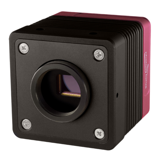
Product Specification 3.1 Introduction The Photonfocus MV3-D640I-M01 camera series is built around the CMOS InGaAs image sensor Snake SW from Sofradir, that provides a resolution of 640 x 512 pixels. The cameras are aimed at applications in industrial image processing where high sensitivity within the SWIR band from 0.9 to 1.7 m are required. - Page 14 3 Product Specification Figure 3.1: Photonfocus MV3-D640I-M01-144-G2 GigE interface camera MAN076 09/2017 V1.0 14 of 121...
-
Page 15: Feature Overview
3.2 Feature Overview 3.2 Feature Overview The general specification and features of the camera are listed in the following sections. The detailed description of the camera features is given in the following chapters. Characteristics Photonfocus MV3-D640I-M01 GigE Series Interface Gigabit Ethernet (PoE), GigE Vision and GenICam compliant Camera Control GigE Vision Suite Trigger Modes... -
Page 16: Technical Specification
3 Product Specification 3.3 Technical Specification Photonfocus MV3-D640I-M01 GigE Series Sensor Manufacturer / Type Sofradir / Snake SW Technology CMOS active pixel, InGaAs Optical format / diagonal 1 / 1.7” (12.3 mm diagonal) Resolution 640 x 512 pixels Pixel size 15 m x 15 m Active optical area 9.6 mm x 7.68 mm... -
Page 17: Absolute Maximum Ratings
3.3 Technical Specification Photonfocus MV3-D640I-M01 GigE Series Interface Gigabit Ethernet interface, GigE Vision and GenICam compliant Operating temperature / moisture 0°C ... 50°C / 20 ... 80 % Storage temperature / moisture -25°C ... 60°C / 20 ... 95 % Trigger signal input range +5 .. -
Page 18: Electrical Characteristics
3 Product Specification 3.3.2 Electrical Characteristics Parameter Value Camera Control Input Single Ended +5 V ... +20 V Table 3.5: Electrical Characteristics 3.3.3 Spectral Response Fig. 3.2 shows the quantum efficiency curve of the Snake SW sensors from Sofradir measured in the wavelength range from 900 nm to 1800 nm. -
Page 19: Image Acquisition
Image Acquisition This chapter gives detailed information about the controlling of the image acquisition. It shows how the camera can be triggered or run in free-running mode, and how the frame rate can be configured. The structure offers a lot of flexibility in the configuration. It follows the GenI- Cam naming convention. -
Page 20: Image Acquisition, Frame And Exposure Control Parameters
4 Image Acquisition Acquisition Control The acquisition control block takes care of the acquisition function. The camera can only capture frames, when the acquisition has been started and is active (see Section 4.2 for more information). Frame Control The frame control block takes care of the capturing of one or many frames and burst of frames (see Section 4.3 for more information). -
Page 21: Image Acquisition, Frame And Exposure Trigger
4.2 Acquisition Control 4.1.4 Image Acquisition, Frame and Exposure Trigger The camera can run in "free-running" mode, which means that it captures images automatically in full frame rate once the acquisition has been started. However the acquisition and image capturing can be controlled by triggers. For this purposes, there are seven triggers available: •... -
Page 22: Acquisition Frame Rate And Acquisition Frame Rate Enable
4 Image Acquisition A c q u i s i t i o n T r i g g e r W a i t ) c q u i s i t i o n C o n t r o l A c q u i s i t i o n A c t i v e A c q u i s i t i o n S t a r t T r i g g e r ) c q u i s i t i o n S t a r t ( ) -
Page 23: Acquisition Start Trigger
4.2 Acquisition Control 4.2.3 Acquisition Start Trigger The acquisition start trigger can be used to control the acquisition start procedure. The main property of this trigger is the trigger mode. It can be set to on or off: Acquisition Start Trigger Mode = on As soon as the acquisition is started by executing of the acquisition start command, the camera goes into the state "Acquisition Trigger Wait". -
Page 24: Acquisition Control Output Signals
4 Image Acquisition 4.2.5 Acquisition Control Output Signals The acquisition control block has the following output signals: Acquisition Trigger Wait An asserted acquisition trigger wait indicates, that the acquisition control is waiting for an acquisition start trigger (see Section 4.2.3). Acquisition Active Acquisition active is a status signal, which is asserted, when the acquisition has been started and deasserted, when the acquisition is stopped. -
Page 25: Frame Burst Start Trigger
4.3 Frame Control The camera runs in free-running mode when the mode of both triggers, the frame start trigger and frame burst start trigger, is set to off and the exposure mode is set to "Timed" (see Section 4.4.1 for more information about the expo- sure mode). -
Page 26: Frame Burst End Trigger
4 Image Acquisition start triggers are ignored. As soon as an acquisition start trigger has been received, the camera waits for frame triggers. It can be a frame start trigger or a frame burst start trigger. Depending which trigger - frame start or frame burst start - arrives first, the camera starts a single frame or burst of frame acquisition. -
Page 27: Exposure Control
4.4 Exposure Control Frame End The frame end is an event, which is generated, when a frame is finished. Frame Burst Start The frame burst start is an event, which is generated, when a new burst of frame starts. Frame Burst End The frame burst end is an event, which is generated, when a burst of frame is finished. -
Page 28: Exposure End Trigger
4 Image Acquisition Exposure Start Trigger Mode = off The exposure start triggers are ignored. The exposure start trigger is only available, when the exposure mode is set to "trigger controlled". The camera sets the trigger modes of this trigger automat- ically to on, when the exposure mode is set to "trigger controlled"... -
Page 29: Overlapped Image Acquisition Timing
4.5 Overlapped Image Acquisition Timing Exposure Start The exposure start is an event, which is generated, when a new exposure time has been started. Exposure End The exposure end is an event, which is generated, when a currently running exposure time is finished. Exposure active status signal is routed to the I/O control block and can there be selected for output on the physical output line or on one of the available leds. -
Page 30: Acquisition-, Frame- And Exposure-Trigger Configuration
4 Image Acquisition Exposure Time > Read Out Time An new exposure cycle can be started as soon as the read out of the previous frame has been started (See Fig. 4.11). Exposure Time < Read Out Time The start of a new exposure has delayed by a certain amount of time in order to ensure, that the exposure doesn’t end prior to the image read out end of the previous frame (See Fig. -
Page 31: Trigger Source Selection
4.6 Acquisition-, Frame- and Exposure-Trigger Configuration - x p o s u r e E n d T r i g g e r E x p o s u r e S t a r t T r i g g e r F r a m e B u r s t E n d... -
Page 32: Trigger Mode
4 Image Acquisition 4.6.3 Trigger Mode The trigger mode defines, if the trigger is active. Following settings are available: • • 4.6.4 Trigger Activation The trigger activation defines, which edge of the selected trigger is processed in the trigger signal path. Following configuration is available: •... - Page 33 4.7 Software Signal Pulse and User Output The user output block is an eight bit status register. The bits can be set to 0 or 1 by software. The bits are available in the following firmware blocks/functions: • Counter Trigger •...
- Page 34 4 Image Acquisition MAN076 09/2017 V1.0 34 of 121...
-
Page 35: Counter & Timer
Counter & Timer 5.1 Counter + o u n t e r A c t i v a t i o n C o u n t e r 4 i s i n g E d g e T r i g g e r F a l l i n g E d g e B o t h... -
Page 36: Counter Status
5 Counter & Timer If additionally a trigger source is selected, the counter is waiting for a trigger. It ignores counter events until a valid trigger event has been received. A valid trigger signal on the selected trigger source starts the counter, which means, that it counts the predefined number of events from the start value according to the counter start value and duration configuration. -
Page 37: Counter Event Source
5.1 Counter Counter Trigger Source != Off The state of the counter changes to "trigger wait". The counter reset source can be set to the counter end signal of the same counter. This allows to restart the counter automatically as soon as it arrives its end condition. -
Page 38: Counter Trigger Source
5 Counter & Timer Line input source has additionally a activation configuration, which needs to be set accordingly. Following configuration values are available: Rising Edge Counter counts rising edges on the selected line input. Falling Edge Counter counts falling edges on the selected line input Both Edges Counter counts both edges on the selected line input Activation configuration has only effect when line input is selected as a counter event source, otherwise this configuration is ignored. -
Page 39: Counter Reset Source
5.1 Counter Line Input Starts when the specified counter trigger activation condition is met on the chosen line. Line input source has additionally an activation configuration, which needs to be set accordingly. Following configuration values are available: Rising Edge Counter starts with the rising edge on the selected line input. Falling Edge Counter starts with the falling edge on the selected line input Both Edges Counter starts with any edge on the selected line input Level High Counter starts and is counting events as long as the level is high. -
Page 40: Timer
5 Counter & Timer Timer 0 ... 3 Start Resets with the reception the chosen timer start event. Timer 0 ... 3 End Resets with the reception the chosen timer end event. Software Signal Pulse 0 ... 7 Resets with the reception of chosen software signal pulse event (see Section 4.7). -
Page 41: Timer Status
5.2 Timer When the timer trigger source is set to off (see Section 5.2.5), a software timer reset command starts the timer immediately (see Section 5.2.4). The current timer value can be read via software. A start value can also be set, which means, that the timer starts from this configured value instead from zero. - Page 42 5 Counter & Timer Acquisition End Starts with the reception of the acquisition end event. FrameTrigger Starts with the reception of the frame trigger event. Frame Start Starts with the reception of the frame start event. Frame End Starts with the reception of the frame end event. Frame Burst Start Starts with the reception of the frame burst start event.
-
Page 43: I/O Control
I/O Control This chapter shows the structure of the physical input and physical output line. It describes the signal path and how to configure it. The I/O control block contains a signal input path and a signal output path. 6.1 Input Signal Path The camera has two physical signal input lines, which come from the input opto-isolators of the camera hardware interface (see Section 12.6) and which are fed into the input signal path of the camera. -
Page 44: Output Signal Path
6 I/O Control Line Input Camera Input Line0 ISO_IN0 Line1 ISO_IN1 Table 6.1: Line Input Mapping O u t p u t S i g n a l P a t h " L E D S 0 " O u t p u t S i g n a l P a t h " L E D S 1 "... - Page 45 6.2 Output Signal Path bright and slowly to dark again. Every time, when the camera is acquiring and sending images, the LED changes to a blinking characteristic. If the source serial communication is selected, the led flashes every time when the host communicates with the camera, due to changing or reading of camera parameters.
- Page 46 6 I/O Control MAN076 09/2017 V1.0 46 of 121...
-
Page 47: Image Format Control
Image Format Control There are several possibilities to focus on the interesting parts of an image: • Region of Interest (ROI) (see Section 7.1) • Multiple Regions of Interest (MROI) (see Section 7.2) These features can help to reduce the number of pixels read from the image sensor which leads to an increased frame rate (see Chapter 8 for more information about the available frame rate). - Page 48 7 Image Format Control On the left-hand side an example of ROI is shown and on the right-hand side an example of MROI. It can be readily seen that the resulting image with MROI is smaller than the resulting image with ROI only and the former will result in an increase in image frame rate. R O I .
- Page 49 7.2 Multiple Regions of Interest (MROI) Figure 7.2: Multiple Regions of Interest with 5 ROIs MAN076 09/2017 V1.0 49 of 121...
- Page 50 7 Image Format Control Fig. 7.3 shows an example from hyperspectral imaging where the presence of spectral lines at known regions need to be inspected. By using a MROI only a 640x54 region need to be readout and a frame rate of 2600 fps can be achieved. Without using MROI the resulting frame rate would be 300 fps for a 640x512 ROI.
-
Page 51: Frame Rate
Frame Rate 8.1 Introduction The maximal frame rate of the camera depends on the camera settings. The following factors influence the maximal frame rate (see also Table 8.2): • The read-out mode configuration: Sequential [non overlapping] or Interleave [overlapping]) (Section 8.2). •... -
Page 52: Common Parameters
8 Frame Rate 8.3 Common parameters Some parameters and formulas that are used in the following sections are: ReadoutTime = (Width/16 + 18)*(Height + 1) / 9 * 10 The maximal frame rate only considering the maximal data rate is: MaxFrameRateData = MaxDataRateInterface / (Width * Height * BitsPerPixel) Where BitsPerPixel is 8 in Mono8 pixel format, 12 in Mono10Packed and Mono12Packed pixel formats and 16 in Mono10 and Mono12 pixel formats. -
Page 53: Interleave Read-Out Timing 2
8.6 Interleave Read-out Timing 2 F r a m e < n > F r a m e < n + 1 > 6 r i g g e r - x p o s u r e T i m e E x p o s u r e R e a d o u t T I n t S a m p l i n g... -
Page 54: Maximum Frame Rate Table
8 Frame Rate 8.8 Maximum Frame Rate Table A list of common used image dimension and its frame rates is shown in Table 8.2. It shows the maximum possible frame rates when the exposure time is smaller than the read out time. There is a frame rate calculator in the support section of the Photonfocus web page www.photonfocus.com, which allows to determine the frame rates for any available image dimensions and expsoure time settings. -
Page 55: Pixel Data Processing
Pixel Data Processing 9.1 Overview The pixel, which are read out of the image sensor, are processed in the cameras data path. The sequence of blocks is shown in figure Fig. 9.1. 1 m a g e S e n s o r N o n - U n i f o r m i t y C o r r e c t i o n D i g i t a l O f f s e t / G a i n... -
Page 56: Image Correction
9 Pixel Data Processing 9.2 Image Correction 9.2.1 Overview The camera possesses image pre-processing features, that compensate for non-uniformities caused by the sensor, the lens or the illumination. This method of improving the image quality is generally known as ’Shading Correction’ or ’Flat Field Correction’ and consists of a combination of offset correction, gain correction and pixel interpolation. - Page 57 9.2 Image Correction " a v e r a g e o f b l a c k r e f e r e n c e p i c t u r e > l a c k r e f e r e n c e o f f s e t c o r r e c t i o n i m a g e m a t r i x...
-
Page 58: Gain Correction
9 Pixel Data Processing 9.2.3 Gain Correction The gain correction is based on a grey reference image, which is taken at uniform illumination to give an image with a mid grey level. Gain correction is not a trivial feature. The quality of the grey reference image is crucial for proper gain correction. -
Page 59: Hot And Cold Pixel Correction
9.2 Image Correction 0 . 8 0 . 9 a v e r a g e o f g r a y 1 . 2 0 . 8 1 . 3 1 . 2 r e f e r e n c e 0 . -
Page 60: Corrected Image
9 Pixel Data Processing Histogram of the uncorrected grey reference image grey reference image ok grey reference image too bright 2400 2600 2800 3000 3200 3400 3600 3800 4000 4200 Grey level, 12 Bit [DN] Figure 9.5: Proper grey reference image for gain correction Defect pixel correction If the hot pixel correction is switched on, the camera replaces the value of a defect pixel by an average of its neighbour pixels (see Fig. -
Page 61: Correction Ranges
9.2 Image Correction 0 . 8 0 . 9 1 . 2 0 . 8 1 . 3 1 . 2 0 . 9 ? u r r e n t i m a g e o f f s e t c o r r e c t i o n g a i n c o r r e c t i o n c o r r e c t e d i m a g e m a t r i x... -
Page 62: Gain And Offset
9 Pixel Data Processing 9.3 Gain and Offset There are different gain settings on the camera: Gain (Digital Fine Gain) Digital fine gain accepts fractional values from 0.01 up to 15.99. It is implemented as a multiplication operation. Digital Gain Digital Gain is a coarse gain with the settings x1, x2, x4 and x8. It is implemented as a binary shift of the image data where ’0’... - Page 63 9.4 Grey Level Transformation (LUT) y = f ( x ) m a x m a x Figure 9.8: Commonly used LUT transfer curves Grey level transformation − Gain: y = (255/1023) ⋅ a ⋅ x a = 1.0 a = 2.0 a = 3.0 a = 4.0 1000...
-
Page 64: Gamma
9 Pixel Data Processing 9.4.2 Gamma The ’Gamma’ mode performs an exponential amplification, configurable in the range from 0.4 to 4.0. Gamma > 1.0 results in an attenuation of the image (see Fig. 9.10), gamma < 1.0 results in an amplification (see Fig. 9.11). Gamma correction is often used for tone mapping and better display of results on monitor screens. -
Page 65: User-Defined Look-Up Table
9.4 Grey Level Transformation (LUT) 9.4.3 User-defined Look-up Table In the ’User’ mode, the mapping of input to output grey levels can be configured arbitrarily by the user. There is an example file in the PFRemote folder. LUT files can easily be generated with a standard spreadsheet tool. - Page 66 9 Pixel Data Processing ( 0 , 0 ) N N N N O O L U T 0 O L U T 1 O m a x m a x Figure 9.13: Overlapping Region-LUT example...
- Page 67 9.4 Grey Level Transformation (LUT) Fig. 9.15 shows the application of the Region-LUT to a camera image. The original image without image processing is shown on the left-hand side. The result of the application of the Region-LUT is shown on the right-hand side. One Region-LUT was applied on a small region on the lower part of the image where the brightness has been increased.
-
Page 68: Binning
9 Pixel Data Processing 9.5 Binning 9.5.1 Description Binning sums the pixels in subsequent columns and rows, according to the binning configuration. The result is then divided by the number of binned pixels. The binning feature will result in images with lower resolution but significantly higher SNR. For instance, 2x2 binning will result in roughly twice the SNR (in bright areas of the image). - Page 69 9.6 Crosshairs allows to set any grey level to get the maximum contrast depending on the acquired image. The x/y position and the grey level can be set via the camera software. Figure Fig. 9.17 shows two examples of the activated crosshairs with different grey values. One with white lines and the other with black lines.
- Page 70 9 Pixel Data Processing ( 0 , 0 ) 0 , 0 ) , G r e y L e v e l ) a b s o l u t a b s o l u t R O I R O I , G r e y L e v e l ) a b s o l u t...
-
Page 71: Status Line And Image Information
9.7 Status Line and Image Information 9.7 Status Line and Image Information There are camera properties available that give information about the acquired images, such as integration time, ROI settings or average image value. These properties can be queried by software. - Page 72 9 Pixel Data Processing Start pixel index Parameter width [bit] Parameter Description Preamble: 0x66BB00FF Counter 0 Value (see Section 5.1) Counter 1 Value (see Section 5.1) Counter 2 Value (see Section 5.1) Counter 3 Value (see Section 5.1) Timer 0 Value in units of clock cycles (see Section 5.2) Timer 1 Value in units of clock cycles (see Section 5.2)
-
Page 73: Camera Type Codes
9.8 Test Images 9.7.3 Camera Type Codes Camera Model Camera Type Code MV3-D640I-M01-144-G2-12 Table 9.5: Type codes of Photonfocus MV3-D640-M01 GigE cameras series 9.8 Test Images Test images are generated in the camera FPGA, independent of the image sensor. They can be used to check the transmission path from the camera to the frame grabber. -
Page 74: Troubleshooting Using The Lfsr
9 Pixel Data Processing Figure 9.21: LFSR (linear feedback shift register) test image 9.8.3 Troubleshooting using the LFSR To control the quality of your complete imaging system enable the LFSR mode, set the camera window to 512 x 512 pixels (x=0 and y=0) and check the histogram. If your frame grabber application does not provide a real-time histogram, store the image and use a graphic software tool to display the histogram. - Page 75 9.8 Test Images Figure 9.23: LFSR test pattern received at the frame grabber and histogram containing transmission errors In robots applications, the stress that is applied to the camera cable is especially high due to the fast movement of the robot arm. For such applications, special drag chain capable cables are available.
- Page 76 9 Pixel Data Processing MAN076 09/2017 V1.0 76 of 121...
-
Page 77: Thermoelectric Cooler (Tec)
Thermoelectric Cooler (TEC) 10.1 TEC Description The sensor has an integrated thermoelectrical cooler (TEC) which is driven by camera electronic to stabilize the temperature of the sensor. The performance of the camera TEC is mainly limited by the heat transfer capability of the system setup. The sensor TEC is controlled by a PID controller which can cool and heat the sensor. - Page 78 10 Thermoelectric Cooler (TEC) MAN076 09/2017 V1.0 78 of 121...
-
Page 79: Precautions
Precautions 11.1 IMPORTANT NOTICE! READ THE INSTRUCTIONS FOR USE BEFORE OPERATING THE CAMERA STORE THE INSTRUCTIONS FOR USE FOR FURTHER READING The installation of the camera in the vision system should be executed by trained and instructed employees. DANGER - Electric Shock Hazard Unapproved power supplies may cause electric shock. - Page 80 11 Precautions Incorrect plugs can damage the camera connectors. Use only the connectors specified by Photonfocus in this manual. Using plugs designed for a smaller or a larger number of pins can damage the connectors. The cameras deliver the data to the vision system over interfaces with high band- width.
- Page 81 11.1 IMPORTANT NOTICE! Cleaning of the housing To clean the surface of the camera housing: • Before cleaning disconnect the camera from camera power supply and I/O connectors. • Do not use aggressive solvents or thinners which can damage the surface, the serial number label and electronic parts.
- Page 82 11 Precautions MAN076 09/2017 V1.0 82 of 121...
-
Page 83: Hardware Interface
Hardware Interface 12.1 Absolute Maximum Ratings Parameter Value Camera Control Input Signal Voltage Single Ended -0 V ... +24 V Camera Control Output Signal Voltage Single Ended 0 V ... +24 V Camera Control Output Signal Output Current Single Ended 0.5 A Camera Control Output Signal Output Power Single Ended 0.35 W... - Page 84 12 Hardware Interface Figure 12.1: Rear view of the GigE camera It is extremely important that you apply the appropriate voltages to your camera. Incorrect voltages will damage the camera. For further details including the pinout please refer to Appendix Appendix A. MAN076 09/2017 V1.0 84 of 121...
-
Page 85: Status Indicator (Gige Cameras)
12.5 Status Indicator (GigE cameras) 12.5 Status Indicator (GigE cameras) Six LEDs on the back of the camera gives information about the current status of the GigE CMOS cameras. LED S0, S1 and S2 (from left to right) are configurable. It can be selected, which camera status information is shown by these LEDs (see Section 6.2 for the available camera status signals). - Page 86 12 Hardware Interface C a m e r a 1 S O _ I N 0 L i n e I n 0 C u r r e n t L i m i t e r I S O _ G N D C A M E R A _ G N D I S O _ I N 1 L i n e I n 1...
-
Page 87: Single-Ended Line Input
12.6 I/O Connector 12.6.2 Single-ended Line Input ISO_IN is a single-ended isolated input (see Fig. 12.2). Fig. 12.3 shows a direct connection to the ISO_IN input. 1 2 p o l . F i s c h e r C a m e r a C o n n e c t o r 1 S O _ I N C u r r e n t... -
Page 88: Single-Ended Line Output
12 Hardware Interface 12.6.3 Single-ended Line Output ISO_OUT is a single-ended isolated output. Fig. 12.5 shows the connection from the ISO_OUT output to a TTL logic device. 1 2 p o l . F i s c h e r C o n t r o l L o g i c C a m e r a C o n n e c t o r... -
Page 89: Master / Slave Camera Connection
12.6 I/O Connector 12.6.4 Master / Slave Camera Connection The trigger input of one Photonfocus MV3 camera can easily be connected to the strobe output of another Photonfocus MV3 camera as shown in Fig. 12.8. This results in a master/slave mode where the slave camera operates synchronously to the master camera. -
Page 90: I/O Wiring
12 Hardware Interface 12.6.5 I/O Wiring The Photonfocus cameras include electrically isolated inputs and outputs. Take great care when wiring trigger and strobe signals to the camera, specially over big distances (a few meters) and in noisy environments. Improper wiring can introduce ground loops which lead to malfunction of triggers and strobes. - Page 91 12.6 I/O Connector Common Grounds with Star Wiring Ground loops can be avoided using "star wiring", i.e. the wiring of power and ground connections originate from one "star point" which is typically a power supply. Fig. 12.10 shows a schematic of the star-wiring concept. Fig.
- Page 92 12 Hardware Interface Fig. 12.12 shows an example of how to connect a flash light and a trigger source to the camera using star-wiring. The trigger in this example is generated from a light barrier. Note how the power and ground cables are connected to the same power supply. S t a r t P o i n t 2 o w e r S u p p l y S T R...
- Page 93 12.6 I/O Connector An example of improper wiring that causes a ground loop is shown in Fig. 12.13. C o n n e c t i n g C A M _ G N D a n d G r o u n d l o o p I S O _ G N D t h e w r o n g w a y 1 s o l a t o r I S O _ I N...
- Page 94 12 Hardware Interface MAN076 09/2017 V1.0 94 of 121...
-
Page 95: Miscellaneous
Miscellaneous 13.1 Mechanical Interface During storage and transport, the camera should be protected against vibration, shock, moisture and dust. The original packaging protects the camera adequately from vibration and shock during storage and transport. Please either retain this packaging for possible later use or dispose of it according to local regulations. -
Page 96: Optical Interface
13 Miscellaneous 13.2 Optical Interface 13.2.1 Cleaning the Sensor The sensor is part of the optical path and should be handled like other optical components: with extreme care. Dust can obscure pixels, producing dark patches in the images captured. Dust is most visible when the illumination is collimated. - Page 97 13.2 Optical Interface Product Supplier Remark EAD400D Airduster Electrolube, UK www.electrolube.com Anticon Gold 9"x 9" Wiper Milliken, USA ESD safe and suitable for class 100 environments. www.milliken.com TX4025 Wiper Texwipe www.texwipe.com Transplex Swab Texwipe Small Q-Tips SWABS Q-tips Hans J. Michael GmbH, www.hjm-reinraum.de BB-003 Germany...
-
Page 98: Temperature Monitor
13 Miscellaneous 13.3 Temperature Monitor The camera contains a temperature monitor system to protect the camera electronics from damage due to excessive heat. There are 3 temperature sensing diodes in the camera: Sensor PCB: Temperature diode on the sensor board. Proc PCB: Temperature diode on the processor board. -
Page 99: Troubleshooting
Troubleshooting 14.1 No images can be acquired If no images can be acquired then the cause could be one of the following: Camera is not triggered: see Section 14.1.1 First proceed with the above listed action. If still no images can be acquired then write an e-mail to Photonfocus support (support@photonfocus.com). - Page 100 14 Troubleshooting MAN076 09/2017 V1.0 100 of 121...
-
Page 101: Standards Compliance
Standards Compliance 15.1 Directives and General Standards The products described in this manual in the form as delivered are in conformity with the provisions of the following European Directives: • 2014/30/EU Electromagnetic compatibility (EMC) • 2014/35/EU Low Voltage (LVD) • 2011/65/EU Restriction of hazardous substances (RoHS) Conformity to the Directives is assured through the application of the following standards: Emission:... -
Page 102: For Customers In Canada
15 Standards Compliance You are cautioned that any changes or modifications not expressly approved in this manual could void your authority to operate this equipment. The shielded interface cable recommended in this manual must be used with this equipment in order to comply with the limits for a computing device pursuant to Subpart B of Part 15 of FCC Rules. -
Page 103: Warranty
Warranty The manufacturer alone reserves the right to recognize warranty claims. 16.1 Warranty Terms The manufacturer warrants to distributor and end customer that for a period of two years from the date of the shipment from manufacturer or distributor to end customer (the "Warranty Period") that: •... - Page 104 16 Warranty Avoid cleaning the sensor with improper methods. Follow the instructions in the corresponding chapter of this manual. Transport and store the camera in its original packaging only and protect the sensor and the lens mount with a camera body cap. 10.
-
Page 105: Support And Repair
Support and Repair This chapter describes the product support and repair. 17.1 Technical Support First level technical support is given from the sales department of Photonfocus or your local dealer. In case your issue could not be solved in this way Photonfocus support team takes over. The Photonfocus support team is available via email: support@photonfocus.com. - Page 106 17 Support and Repair MAN076 09/2017 V1.0 106 of 121...
-
Page 107: References
References All referenced documents can be downloaded from our website at www.photonfocus.com. AN0032 Application Note "PFRemote/SDK and Win64bit", Photonfocus, April 2011 MAN076 09/2017 V1.0 107 of 121... - Page 108 18 References MAN076 09/2017 V1.0 108 of 121...
-
Page 109: A.1 Power Supply Connector
Pinouts A.1 Power Supply Connector The power supply plugs are available from Fischer connectors at www.fischerconnectors.com. Fig. A.1 shows the power supply plug from the solder side. The pin assignment of the power supply plug is given in Table A.1. The receptacle used on the camera is Fischer DBPLU1031Z012–130G. -
Page 110: A Pinouts
A Pinouts I/O Type Name Description ISO_OUT0 General purpose output 0 (opto-isolated) ISO_OUT1 General purpose output 1 (opto-isolated) RESERVED Do not connect Camera ground Camera power +12 V DC ( 10%) ISO_GND Signal ground for opto-isolated output signals ISO_IN0 General purpose input 0 (opto-isolated) ISO_IN1 General purpose input 1 (opto-isolated) RESERVED... -
Page 111: A.2 Gige Connector
A.2 GigE Connector A.2 GigE Connector An X-coded M12 connector is used for the GigE interface and power supply of the camera. Suitable GigE interface cables can be ordered from your Photonfocus dealership. MAN076 09/2017 V1.0 111 of 121... - Page 112 A Pinouts MAN076 09/2017 V1.0 112 of 121...
-
Page 113: B.1 Timed Exposure Mode Camera Timing
Camera Timing B.1 Timed Exposure Mode Camera Timing Fig. B.1 shows a timing example, when the camera capture frames with rising edges on the camera ISO_IN input. The external signal, which is fed into the cameras ISO_IN input is isolated by an opto-isolator. -
Page 114: B Camera Timing
B Camera Timing 1 S O _ I N L i n e I n i s o - i n I n t e r n a l L i n e I n P u l s e i n p u t - j i t t e r D e l a y e d L i n e I n P u l s e p u l s e - d e l a y... -
Page 115: C.1 Acquisition
Use Cases This chapter shows some typical configurations of the camera. It gives some tips, how to acquire images and how to use the general purpose counters and timers. C.1 Acquisition This section shows some configuration procedures of frequently used acquisition situations. C.1.1 Camera runs in "free-running"... -
Page 116: C.1.4 Camera Runs In Burst Triggered Mode
C Use Cases The TriggerMode of FrameStart trigger must be set to On. The AcquisitionStart, FrameBurstStart and the ExposureStart must be set to Off. The TriggerSource of the FrameStart trigger must be set to the corresponding source. For instances to Line0. Since the source is set to Line0, the TriggerActivation must be set accordingly: RisingEdge, FallingEdge or AnyEdge. -
Page 117: C.2 Timer
C.2 Timer The TriggerSource of the ExposureStart trigger must be set to Line0. The TriggerActivation of the ExposureStart trigger must be set to RisingEdge. The TriggerSource of the ExposureEnd trigger must be set to Line0. The TriggerActivation of the ExposureEnd trigger must be set to FallingEdge. TriggerDelay and TriggerDivider of the ExposureStart and ExposureEnd trigger must be set accordingly. -
Page 118: C.3.1 Counter Reset
C Use Cases C.3.1 Counter Reset A counter needs to be reset in order to be activated after configuration. This can be done by the software reset command CounterReset or by an external reset source, which can be selected by the parameter CounterResetSource of the corresponding counter. Furthermore for each counter there is an automatically counter reset at acquisition start feature available: CounterAcquisitionStartReset. - Page 119 C.3 Counter Select one of the four available counters by setting of the CounterSelector to Counter0, Counter1, Counter2 or Counter3. Set the corresponding CounterEventSource to MissedAcqStartTrigger, MissedFrameStartTrigger, MissedFrameBurstStartTrigger, MissedExposureStartTrigger or MissedTrigger. Parameter TimerTriggerActivation can be ignored. This configuration is only necessary, when Line0 input is selected as a trigger source.
- Page 120 C Use Cases MAN076 09/2017 V1.0 120 of 121...
- Page 121 Document Revision History Revision Date Changes July 2017 First version MAN076 09/2017 V1.0 121 of 121...
Need help?
Do you have a question about the MV3-D640I-M01-144-G2-12 and is the answer not in the manual?
Questions and answers