Table of Contents
Advertisement
Quick Links
Advertisement
Table of Contents
Troubleshooting

Related Manuals for Photon Focus OEM0 Series


Summary of Contents for Photon Focus OEM0 Series
- Page 1 Photonfocus MV0/OEM0 Pregius Camera Series CMOS camera series with GigE Interface MV0-D1920-S01-240-G2 MV0-D2448-S01-240-G2 MV0-D2448P-S01-240-G2 DR0-D1920-S01-240-G2 DR0-D2448-S01-240-G2 OEM0-D1920-S01-240-G2 OEM0-D2448-S01-240-G2 MAN079 08/2020 V1.3...
- Page 2 All information provided in this manual is believed to be accurate and reliable. No responsibility is assumed by Photonfocus AG for its use. Photonfocus AG reserves the right to make changes to this information without notice. Reproduction of this manual in whole or in part, by any means, is prohibited without prior permission having been obtained from Photonfocus AG.
-
Page 3: Table Of Contents
Contents 1 Preface 1.1 IMPORTANT NOTICE! ........1.2 About Photonfocus . - Page 4 CONTENTS 4.4 Exposure Control ........34 4.4.1 Exposure Mode .
- Page 5 CONTENTS 11 Image Data Processing 11.1 Overview ..........65 11.2 Gain and Offset .
- Page 6 CONTENTS 16 Standards Compliance 16.1 Directives and General Standards ......103 16.2 Country-specific Information .
-
Page 7: Preface
Preface 1.1 IMPORTANT NOTICE! READ THE INSTRUCTIONS FOR USE BEFORE OPERATING THE CAMERA STORE THE INSTRUCTIONS FOR USE FOR FURTHER READING Photonfocus AG Bahnhofplatz 10 CH-8853 Lachen SZ Switzerland www.photonfocus.com info@photonfocus.com +41 – 55 451 00 00 MAN079 08/2020 V1.3 7 of 123... -
Page 8: About Photonfocus
1 Preface 1.2 About Photonfocus The Swiss company Photonfocus is one of the leading specialists in the development of CMOS image sensors and corresponding industrial cameras for machine vision. Photonfocus is dedicated to making the latest generation of CMOS technology commercially available. -
Page 9: Legend
1.6 Legend Photonfocus can not be held responsible for any technical or typographical er- rors. 1.6 Legend In this documentation the reader’s attention is drawn to the following icons: Important note, additional information Important instructions General warning, possible component damage hazard Warning, electric shock hazard Warning, fire hazard MAN079 08/2020 V1.3... - Page 10 1 Preface MAN079 08/2020 V1.3 10 of 123...
-
Page 11: Introduction
Introduction 2.1 Introduction This manual describes standard Photonfocus MV0 Pregius series cameras that have a Gigbit Ethernet (GigE) interface. The cameras contain the image sensors IMX174 and IMX250 from Sony. DR cameras use a proprietary coding algorithm to double the maximal frame rate compared to a standard GigE camera over one GigE cable. -
Page 12: Camera List
2 Introduction 2.3 Camera list A list of all cameras covered in this manual is shown in Table 2.1. Name Resolution Frame Rate Notes MV0-D1920-S01-240-G2 1920 x 1200 48 fps Gigabit Ethernet 2.3 MP monochrome standard camera. MV0-D2448-S01-240-G2 2448 X 2048 22 fps Gigabit Ethernet 5.07 MP monochrome standard camera. -
Page 13: Product Specification 3.1 Introduction
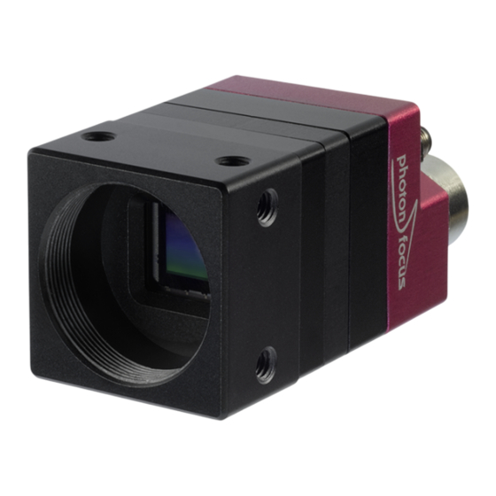
Product Specification 3.1 Introduction The Photonfocus MV0 Pregius GigE camera series is built around the CMOS image sensor IMX174 and IMX250 from Sony. They provide a resolution of 1920 x 1200 (IMX174) and 2448x2048 (IMX250) pixels. The camera series is optimized for low light conditions and there are standard monochrome, colour (C) and polarized (P) models. - Page 14 3 Product Specification Figure 3.1: Photonfocus MV0 Pregius GigE camera series Figure 3.2: Photonfocus OEM0 Pregius GigE camera series MAN079 08/2020 V1.3 14 of 123...
-
Page 15: Feature Overview
3.2 Feature Overview 3.2 Feature Overview The general specification and features of the camera are listed in the following sections. The detailed description of the camera features is given in the following chapters. Characteristics Photonfocus MV0/OEM0 Pregius GigE Camera Series Interface Gigabit Ethernet (PoE), GigE Vision and GenICam compliant Camera Control... -
Page 16: Technical Specification
3 Product Specification 3.3 Technical Specification 2.30 MPix Cameras 5.07 MPix Cameras Sensor Manufacturer Sony Sony Sensor Type IMX174 IMX250 Technology CMOS active pixel Scanning system progressive scan Optical format / diagonal 1/1.2” (13.27 mm diagonal) 2/3” (11.0 mm diagonal) Resolution 1920 x 1200 pixels 2448 x 2048 pixels... -
Page 17: Absolute Maximum Ratings
3.3 Technical Specification 2.30 MPix Cameras 5.07 MPix Cameras Operating temperature / moisture 0°C ... 50°C / 20 ... 80 % Storage temperature / moisture -25°C ... 60°C / 20 ... 95 % Trigger signal input range +5 .. +20 V DC Maximal power consumption <... -
Page 18: Electrical Characteristics
3 Product Specification 3.3.2 Electrical Characteristics Table 13.2 shows the electrical characteristics of the single ended input. Parameter Value Camera Control Input Single Ended +5 V ... +20 V Table 3.5: Electrical Characteristics 3.3.3 Spectral Response Fig. 3.3 and Fig. 3.4 shows the quantum efficiency curve of the monochrome IMX174 and IMX250 sensors from Sony measured in the wavelength range from 400 nm to 1000 nm. - Page 19 3.3 Technical Specification Monochrome 1000 Wavelength [nm] Figure 3.4: Quantum efficiency (QE) [%] of the IMX250 monochrome and near infrared image sensors (with micro lenses) MAN079 08/2020 V1.3 19 of 123...
- Page 20 3 Product Specification Red Bayer Green Bayer Blue Bayer 1000 Wavelength [nm] Figure 3.5: Quantum efficiency (QE) [%] of the IMX174 CMOS color image sensors (with micro lenses) MAN079 08/2020 V1.3 20 of 123...
- Page 21 3.3 Technical Specification Red Bayer Green Bayer Blue Bayer 1000 Wavelength [nm] Figure 3.6: Quantum efficiency (QE) [%] of the IMX250 CMOS color image sensors (with micro lenses) MAN079 08/2020 V1.3 21 of 123...
-
Page 22: Rgb Bayer Pattern Filter (Color Models)
3 Product Specification The color cameras are equipped with a IR cut-off filter to avoid false colors arising when an infra-red component is present in the illumination. Fig. 3.7 shows the transmssion curve of the cut-off filter. Figure 3.7: Transmission curve of the cut-off filter in the Photonfocus MV0 Pyhton GigE cameras 3.4 RGB Bayer Pattern Filter (color models) Fig. -
Page 23: Polarized Pattern Filter (Polarized Models)
3.5 Polarized Pattern Filter (polarized models) 3.5 Polarized Pattern Filter (polarized models) On Fig. 3.9 shows the polarized filter arrangement of the pixel matrix. The numbers correspond to the polarization angle of the light. Figure 3.9: Polarized Pattern Arrangement MAN079 08/2020 V1.3 23 of 123... - Page 24 3 Product Specification MAN079 08/2020 V1.3 24 of 123...
-
Page 25: Image Acquisition
Image Acquisition This chapter gives detailed information about the controlling of the image acquisition. It shows how the camera can be triggered or run in free-running mode, and how the frame rate can be configured. The structure offers a lot of flexibility in the configuration. It follows the GenI- Cam naming convention. -
Page 26: Image Acquisition, Frame And Exposure Control Parameters
4 Image Acquisition Acquisition Control The acquisition control block takes care of the acquisition function. The camera can only capture frames, when the acquisition has been started and is active (see Section 4.2 for more information). Frame Control The frame control block takes care of the capturing of one or many frames and burst of frames (see Section 4.3 for more information). -
Page 27: Image Acquisition, Frame And Exposure Trigger
4.1 Overview 4.1.4 Image Acquisition, Frame and Exposure Trigger The camera can run in "free-running" mode, which means that it captures images automatically in full frame rate once the acquisition has been started. However the acquisition and image capturing can be controlled by triggers. For this purposes, there are seven triggers available: •... -
Page 28: Acquisition Control
4 Image Acquisition 4.2 Acquisition Control A c q u i s i t i o n T r i g g e r W a i t ) c q u i s i t i o n C o n t r o l A c q u i s i t i o n A c t i v e A c q u i s i t i o n S t a r t T r i g g e r ) c q u i s i t i o n S t a r t ( ) -
Page 29: Acquisition Start Trigger
4.2 Acquisition Control ) c q u i s i t i o n S t a r t ( ) A c q u i s i t i o n S t o p ( ) . r a m e F r a m e . -
Page 30: Acquisition End Trigger
4 Image Acquisition 4.2.4 Acquisition End Trigger The acquisition end trigger can be used to control the acquisition end procedure. The main property of this trigger is the trigger mode. It can be set to on or off: Acquisition End Trigger Mode = on When the acquisition status is "Acquisition Active", it goes to "Acquisition Trigger Wait"... -
Page 31: Frame Control
4.3 Frame Control 4.3 Frame Control . r a m e C o n t r o l F r a m e T r i g g e r W a i t F r a m e A c t i v e F r a m e S t a r t T r i g g e r F r a m e S t a r t F r a m e B u r s t S t a r t T r i g g e r... -
Page 32: Frame Burst End Trigger
4 Image Acquisition A c q u i s i t i o n S t a r t ( ) A c q u i s i t i o n S t o p ( ) . r a m e . -
Page 33: Frame Control Output Signals
4.3 Frame Control A c q u i s i t i o n S t a r t ( ) A c q u i s i t i o n S t o p ( ) . r a m e . -
Page 34: Exposure Control
4 Image Acquisition 4.4 Exposure Control - x p o s u r e C o n t r o l E x p o s u r e A c t i v e E x p o s u r e S t a r t T r i g g e r E x p o s u r e S t a r t E x p o s u r e E n d T r i g g e r E x p o s u r e E n d... -
Page 35: Exposure Control Output Signals
4.4 Exposure Control Exposure End Trigger Mode = on An activated exposure cycle will be terminated and the image read out will be started, as soon as an exposure end trigger has been received. The "Exposure Active" status goes to inactive. Exposure end triggers are only processed, when an exposure start trigger has started a trigger controlled exposure cycle previously. -
Page 36: Overlapped Image Acquisition Timing
4 Image Acquisition 4.5 Overlapped Image Acquisition Timing The camera is able to perform an overlapped image acquisition. It means, a new exposure can be started during the image readout of the previous image. Fig. 4.10 shows an image acquisition procedure when images are captured in overlapped mode. The status "Frame Active"... - Page 37 4.5 Overlapped Image Acquisition Timing which can be counted by a counter (see Section 5.1.5 for more information how to count missed triggers). Fig. 4.11 and Fig. 4.12 shows both timing situations, when the exposure time longer than the read out time and when the exposure time is shorter than the read out time. F r a m e - x p o s u r e R e a d O u t...
-
Page 38: Acquisition-, Frame- And Exposure-Trigger Configuration
4 Image Acquisition 4.6 Acquisition-, Frame- and Exposure-Trigger Configuration The acquisition-, frame- and exposure timing can be controlled by 7 triggers: • Acquisition Start Trigger • Acquisition End Trigger • Frame Start Trigger • Frame Burst Start Trigger • Frame Burst End Trigger •... -
Page 39: Trigger Software
4.6 Acquisition-, Frame- and Exposure-Trigger Configuration Software Signal Pulse A trigger is generated by the software signal pulse, which comes from a common software signal pulse register (see Section 4.7 for more information). Counter Start A trigger signal is generated by the counter start event (see Section 5.1.3 for more information about the counter start event). -
Page 40: Trigger Divider
4 Image Acquisition 4.6.5 Trigger Divider The trigger divider specifies a division factor of the incoming trigger pulses. A division factor of 1 processes every incoming trigger. A division factor of 2 processes every second trigger and so 4.6.6 Trigger Delay The trigger delay lets the user specify a delay, that will be applied between the reception of a trigger event and when the trigger becomes active. -
Page 41: Software Signal Pulse And User Output
4.7 Software Signal Pulse and User Output 4.7 Software Signal Pulse and User Output The software signal pulse block contains eight general purpose registers which allow generating internal pulse signals by software access. These pulse signals are internally connected to following functions, where it can be used to start a procedure: •... - Page 42 4 Image Acquisition MAN079 08/2020 V1.3 42 of 123...
-
Page 43: Counter & Timer
Counter & Timer 5.1 Counter + o u n t e r A c t i v a t i o n C o u n t e r 4 i s i n g E d g e T r i g g e r F a l l i n g E d g e B o t h... -
Page 44: Counter Status
5 Counter & Timer If additionally a trigger source is selected, the counter is waiting for a trigger. It ignores counter events until a valid trigger event has been received. A valid trigger signal on the selected trigger source starts the counter, which means, that it counts the predefined number of events from the start value according to the counter start value and duration configuration. -
Page 45: Counter Event Source
5.1 Counter Counter Trigger Source Off The state of the counter changes to "trigger wait". The counter reset source can be set to the counter end signal of the same counter. This allows to restart the counter automatically as soon as it arrives its end condition. -
Page 46: Counter Trigger Source
5 Counter & Timer MissedFrameBurstStartTrigger Count the number of missed frame burst start triggers. A missed frame burst start trigger event is generated, when a frame burst start trigger cannot be processed. MissedExposureStartTrigger Count the number of missed exposure start triggers. A missed exposure start trigger event is generated, when an exposure start trigger cannot be processed. -
Page 47: Counter Reset Source
5.1 Counter Exposure Start Starts with the reception of the exposure start event. Exposure End Starts with the reception of the exposure end event. User Output 0 ... 7 Starts and counts events as long as the selected user output bit is asserted. When the counter is started, it ignores counter events as long as the corresponding user output bit is deasserted (see Section 4.7). -
Page 48: Timer
5 Counter & Timer FrameTrigger Resets with the reception of the frame trigger. Frame Start Resets with the reception of the frame start event. Frame End Resets with the reception of the frame end event. Frame Burst Start Resets with the reception of the frame burst start event. Frame Burst End Resets with the reception of the frame burst end event. -
Page 49: Timer Usage
5.2 Timer 6 i m e r T i m e r R e s e t ( ) T i m e r S t a t u s T i m e r A c t i v e A c t i v a t i o n T i m e r 6 i m e r V a l u e... -
Page 50: Timer Reset
5 Counter & Timer 5.2.4 Timer Reset The timer can be reset by a software command. It performs a software reset of the timer counter and starts the timer immediately (change to state timer active), when trigger source is set to off; otherwise it goes into the state timer trigger wait. 5.2.5 Timer Trigger Source The timer trigger source selects the events that will be the used to reset and to start the timer. -
Page 51: O Control
I/O Control This chapter shows the structure of the physical input and physical output line. It describes the signal path and how to configure it. The I/O control block contains a signal input path and a signal output path. 6.1 Input Signal Path The camera has two physical signal input lines, which come from the input opto-isolator of the camera hardware interface (see Section 13.6) and which is fed into the input signal path of the camera. - Page 52 6 I/O Control O u t p u t S i g n a l P a t h " L E D S 0 " O u t p u t S i g n a l P a t h " L E D S 1 "...
-
Page 53: Action Control
Action Control ) c t i o n C o n t r o l A c t i o n U n c o n d i t i o n a l M o d e ) c t i o n D e v i c e K e y A c t i o n 3 A c t i o n 2 A c t i o n 3... -
Page 54: Action Control Output
7 Action Control 7.2 Action Control Output The action output signals can be used to trigger other blocks, like counter, timer, acquisition, frame or exposure control. MAN079 08/2020 V1.3 54 of 123... -
Page 55: User Storage
User Storage Photonfocus Cameras provide the user with access to an internal storage that can be used for example for calibration purposes. This can be especially useful for example for 3D applications, or any 2D applications that require calibration on a per-camera basis. The storage can be accessed in two different ways: through the UserStorage_Address1B and the UserStorage_Data1B or UserStorage_Address4B and UserStorage_Data4B. - Page 56 8 User Storage MAN079 08/2020 V1.3 56 of 123...
-
Page 57: Image Format Control
Image Format Control The focus on the interesting parts of an image can be set by the region of interest. The ROI influences the image size which leads into an increased frame rate (see Chapter 10 for more information about the available frame rate). 9.1 Region of Interest (ROI) Some applications do not need full image resolution. - Page 58 9 Image Format Control If MROI is used together with binning, the total configured image height must be a multiple of the vertical binning factor (see Section 11.4). In the color models, every single ROI should start at an even row and should contain an even number rows to have a correct Bayer pattern in the output image.
-
Page 59: Pixel Format
9.3 Pixel format 9.3 Pixel format The pixel format defines the output format of the pixels in the image. Following pixel formats are available. Mono 8 Mono10 Mono12 Mono10 Packed Mono12 Packed However, not all formats are available in all cameras and with each feature. Available pixel formats are dependant on the settings of the double rate algorithm and the binning algorithm. - Page 60 9 Image Format Control MAN079 08/2020 V1.3 60 of 123...
-
Page 61: Frame Rate
Frame Rate The frame rate depends on the image size, the used exposure time and the max data rate of the GigE interface (MaxDataRateInterface). The image size is given by the image size, which can be configured by the ROI, MROI and decimation settings (see Chapter 9). Two different timing situations have to be considered: •... -
Page 62: Maximum Frame Rate
10 Frame Rate 10.3 Maximum Frame Rate A list of common used image dimension and its frame rates is shown on Table 10.1 for standard cameras and on Table 10.2 for DR cameras. It shows the maximum possible frame rates when the exposure time is smaller than the read out time. - Page 63 10.3 Maximum Frame Rate ROI Dimension [Standard] DR0-D1928-S01-G2 (IMX174) DR0-D2448-S01-G2 (IMX250) 2448 x 2048 n.a. 44 fps 2048 x 1536 (QXGA) n.a. 69 fps 1920 x 1200 (WUXGA) 94 fps 94 fps 1920 x 1080 (HD) 105 fps 105 fps 1600 x 1200 (UXGA) 113 fps 113 fps...
- Page 64 10 Frame Rate MAN079 08/2020 V1.3 64 of 123...
-
Page 65: Image Data Processing
Image Data Processing 11.1 Overview The pixel, which are read out of the image sensor, are processed in the cameras data path. The sequence of blocks is shown in figure Fig. 11.1. From Digital Digital Region LUT Image Sensor Gain Offset Receive logic Test... -
Page 66: Gain And Offset
11 Image Data Processing 11.2 Gain and Offset There are three different gain settings on the camera: Analog Gain Analog gain on the image sensor. Available values: x1, x1.6, x2.0, x2.6, x3.2 and x4.0. Note that Digital Offset is applied after the Analog Gain. Gain (Digital Fine Gain) Digital fine gain accepts fractional values from 0.01 up to 15.99. -
Page 67: Gain
11.3 Grey Level Transformation (LUT) y = f ( x ) m a x m a x Figure 11.2: Commonly used LUT transfer curves 11.3.1 Gain The ’Gain’ mode performs a digital, linear amplification with clamping (see Fig. 11.3). It is configurable in the range from 1.0 to 4.0 (e.g. -
Page 68: User-Defined Look-Up Table
11 Image Data Processing 11.3.2 User-defined Look-up Table In the ’User’ mode, the mapping of input to output grey levels can be configured arbitrarily by the user. This procedure is explained in Section C.4. 7 s e r L U T y = f ( x ) 8 b i t 1 2 b i t... - Page 69 11.3 Grey Level Transformation (LUT) ( 0 , 0 ) N N N N O O L U T 0 O L U T 1 O m a x m a x Figure 11.5: Overlapping Region-LUT example...
- Page 70 11 Image Data Processing Fig. 11.7 shows the application of the Region-LUT to a camera image. The original image without image processing is shown on the left-hand side. The result of the application of the Region-LUT is shown on the right-hand side. One Region-LUT was applied on a small region on the lower part of the image where the brightness has been increased.
-
Page 71: Binning
11.4 Binning 11.4 Binning 11.4.1 Description Binning sums the pixels in subsequent columns and rows, according to the binning configuration. The result is then divided by the number of binned pixels. The binning feature will result in images with lower resolution but significantly higher SNR. For instance, 2x2 binning will result in roughly twice the SNR (in bright areas of the image). -
Page 72: Dual Crosshairs
11 Image Data Processing 11.5 Dual Crosshairs Up to two crosshairs can be displayed in the live image. It inserts one or two vertical and horizontal lines into the image. The positions as well as the gray levels of the line for both crosshairs can be set individually via the camera software. - Page 73 11.5 Dual Crosshairs The x- and y-positons are absolute to the sensor pixel matrix. It is independent on the image format settings (see Chapter 9 for more information about the available image format configurations). Fig. 11.10 shows two situations of the crosshairs configuration. The same image format settings are used in both situations.
-
Page 74: Test Images
11 Image Data Processing 11.6 Test Images Test images are generated in the camera FPGA, independent of the image sensor. They can be used to check the transmission path from the camera to the acquisition software. Independent from the configured grey level resolution, every possible grey level appears the same number of times in a test image. - Page 75 11.6 Test Images Figure 11.12: LFSR (linear feedback shift register) test image In the LFSR (linear feedback shift register) mode the camera generates a constant pseudo-random test pattern containing all grey levels. If the data transmission is correctly received, the histogram of the image will be flat (Fig. 11.13). On the other hand, a non-flat histogram (Fig.
-
Page 76: Status Line And Image Information
11 Image Data Processing Figure 11.14: LFSR test pattern received and histogram containing transmission errors 11.7 Status Line and Image Information There are camera properties available that give information about the acquired images, such as integration time, ROI settings or average image value. These properties can be queried by software. - Page 77 11.7 Status Line and Image Information Start pixel index Parameter width [bit] Parameter Description Preamble: 0x66BB00FF Counter 0 Value (see Section 5.1) Counter 1 Value (see Section 5.1) Counter 2 Value (see Section 5.1) Counter 3 Value (see Section 5.1) Timer 0 Value in units of clock cycles (see Section 5.2) Timer 1 Value in units of clock cycles (see Section...
-
Page 78: Camera Type Codes
11 Image Data Processing 11.7.3 Camera Type Codes Camera Model Camera Type Code MV0-D1920-S01-240-G2 MV0-D2448-S01-240-G2 MV0-D2448P-S01-240-G2 DR0-D1920-S01-240-G2 DR0-D2448-S01-240-G2 Table 11.4: Type codes of Photonfocus MV0 Pregius GigE camera series (Footnotes: the corresponding OEM0 variant has the same type code) MAN079 08/2020 V1.3 78 of 123... -
Page 79: Frame Combine
11.8 Frame Combine 11.8 Frame Combine Very high frame rates that are well over 1000 fps can be achieved for small ROIs. Every frame (image) activates an interrupt in the GigE software which will issue a high CPU load or the frame rate can not be handled at all by an overload of interrupts. - Page 80 11 Image Data Processing FrameCombine_ForceTimeout The transmission of the combined frame is forced by writing to the FrameCombine_ForceTimeout property. When the FrameCombine is finished by a timeout, then the remaining data in the combined frame will be filled with filler data: the first two pixels of every filler row have the values 0xBB (decimal 187) and 0x44 (decimal 68).
-
Page 81: Double Rate (Dr Cameras Only)
11.9 Double Rate (DR cameras only) 11.9 Double Rate (DR cameras only) The Photonfocus DR cameras use a proprietary coding algorithm to cut the data rate by almost a factor of two. This enables the transmission of high frame rates over just one Gigabit Ethernet connection, avoiding the complexity and stability issues of Ethernet link aggregation. - Page 82 11 Image Data Processing MAN079 08/2020 V1.3 82 of 123...
-
Page 83: Precautions
Precautions 12.1 IMPORTANT NOTICE! READ THE INSTRUCTIONS FOR USE BEFORE OPERATING THE CAMERA STORE THE INSTRUCTIONS FOR USE FOR FURTHER READING The installation of the camera in the vision system should be executed by trained and instructed employees. DANGER - Electric Shock Hazard Unapproved power supplies may cause electric shock. - Page 84 12 Precautions Incorrect plugs can damage the camera connectors. Use only the connectors specified by Photonfocus in this manual. Using plugs designed for a smaller or a larger number of pins can damage the connectors. The cameras deliver the data to the vision system over interfaces with high band- width.
- Page 85 12.1 IMPORTANT NOTICE! Cleaning of the housing To clean the surface of the camera housing: • Before cleaning disconnect the camera from camera power supply and I/O connectors. • Do not use aggressive solvents or thinners which can damage the surface, the serial number label and electronic parts.
- Page 86 12 Precautions MAN079 08/2020 V1.3 86 of 123...
-
Page 87: Hardware Interface
Hardware Interface 13.1 Absolute Maximum Ratings Parameter Value Camera Control Input Signal Voltage Single Ended 0 V ... +24 V Camera Control Output Signal Voltage Single Ended 0 V ... +24 V Camera Control Output Signal Output Current Single Ended 0.1 A Camera Control Output Signal Output Power Single Ended 0.15 W... -
Page 88: Status Indicator (Gige Cameras)
13 Hardware Interface Figure 13.1: Rear view of the GigE camera 13.5 Status Indicator (GigE cameras) Six LEDs on the back of the camera gives information about the current status of the GigE CMOS cameras. LED S0, S1 and S2 are configurable. It can be selected, which camera status information is showed by these LEDs (see Section 6.2 for the available camera status signals). -
Page 89: I/O Connector
13.6 I/O Connector 13.6 I/O Connector 13.6.1 Overview The 4-pole Binder M5 x 0.5 I/O connector contains one external single-ended line input, one external single-ended line output. The pinout of the I/O connector is described in Appendix A. A suitable trigger breakout cable for Binder 4 pole connector can be ordered from your Photonfocus dealership. -
Page 90: Encoder Interface
13 Hardware Interface 13.6.2 Encoder Interface ISO_IN0 and ISO_IN1 can be used as an A/B encoder inputs. Fig. 13.3 shows how to connect the encoder to the camera. 4 p o l . B i n d e r C a m e r a C o n n e c t o r A / B E n c o d e r... - Page 91 13.6 I/O Connector 4 p o l . B i n d e r C a m e r a C o n t r o l L o g i c C o n n e c t o r Y O U R _ V C C 1 S O _ I N C u r r e n t...
-
Page 92: Single-Ended Line Output
13 Hardware Interface 13.6.4 Single-ended Line Output ISO_OUT is a single-ended isolated output. Fig. 13.6 shows the connection from the ISO_OUT output to a TTL logic device. 4 p o l . B i n d e r C o n t r o l L o g i c C a m e r a C o n n e c t o r Y O U R _ P W R... -
Page 93: Master / Slave Camera Connection
13.6 I/O Connector 13.6.5 Master / Slave Camera Connection The trigger input of one Photonfocus MV0 GigE camera can easily connected to the strobe output of another Photonfocus G2 camera as shown in Fig. 13.9. This results in a master/slave mode where the slave camera operates synchronously to the master camera. - Page 94 13 Hardware Interface MAN079 08/2020 V1.3 94 of 123...
-
Page 95: Mechanical Considerations
Mechanical Considerations 14.1 Mechanical Interface During storage and transport, the camera should be protected against vibration, shock, moisture and dust. The original packaging protects the camera adequately from vibration and shock during storage and transport. Please either retain this packaging for possible later use or dispose of it according to local regulations. -
Page 96: Oem0 Cameras With Gige Interface
14 Mechanical Considerations 14.1.2 OEM0 Cameras with GigE Interface Fig. 14.2 and Fig. 14.3 show the mechanical drawing of the camera housing for the Photonfocus OEM0 GigE camera series. Figure 14.2: Mechanical dimensions of the Photonfocus OEM0 Pregius 2.30 MPix GigE cameras (IMX174) MAN079 08/2020 V1.3 96 of 123... - Page 97 14.1 Mechanical Interface Figure 14.3: Mechanical dimensions of the Photonfocus OEM0 Pregius 5.07 MPix GigE cameras (IMX250) The OEM0 camera stack must not run without a proper cooling system. The PCB stack needs at least to be exposed to an airflow. However the usage of an appropriate heat sink is recommended.
-
Page 98: Oem0 Camera Heat Sink Design
14 Mechanical Considerations The two 1mm pin holes in the sensor front board allows a precise mechanical alignment of the PCB in a custom housing 14.1.3 OEM0 camera heat sink design The OEM0 camera pcb stack needs to be cooled properly. An appropriate heat sink is recommended, which must be attached to the FPGA component. -
Page 99: Optical Interface
14.2 Optical Interface 14.2 Optical Interface 14.2.1 Cleaning the Sensor The sensor is part of the optical path and should be handled like other optical components: with extreme care. Dust can obscure pixels, producing dark patches in the images captured. Dust is most visible when the illumination is collimated. - Page 100 14 Mechanical Considerations Product Supplier Remark EAD400D Airduster Electrolube, UK www.electrolube.com Anticon Gold 9"x 9" Wiper Milliken, USA ESD safe and suitable for class 100 environments. www.milliken.com TX4025 Wiper Texwipe www.texwipe.com Transplex Swab Texwipe Small Q-Tips SWABS Q-tips Hans J. Michael GmbH, www.hjm-reinraum.de BB-003 Germany...
-
Page 101: Troubleshooting
Troubleshooting 15.1 No images can be acquired If no images can be acquired then the cause could be one of the following: Camera is not triggered: see Section 15.1.1 First proceed with the above list in numerical order. If still no images can be acquired go back to step 2. - Page 102 15 Troubleshooting MAN079 08/2020 V1.3 102 of 123...
-
Page 103: Standards Compliance
Standards Compliance 16.1 Directives and General Standards The products described in this manual in the form as delivered are in conformity with the provisions of the following European Directives: • 2014/30/EU Electromagnetic compatibility (EMC) • 2014/35/EU Low Voltage (LVD) • 2011/65/EU Restriction of hazardous substances (RoHS) Conformity to the Directives is assured through the application of the following standards: Emission:... -
Page 104: For Customers In Canada
16 Standards Compliance You are cautioned that any changes or modifications not expressly approved in this manual could void your authority to operate this equipment. The shielded interface cable recommended in this manual must be used with this equipment in order to comply with the limits for a computing device pursuant to Subpart B of Part 15 of FCC Rules. -
Page 105: Warranty
Warranty The manufacturer alone reserves the right to recognize warranty claims. 17.1 Warranty Terms The manufacturer warrants to distributor and end customer that for a period of two years from the date of the shipment from manufacturer or distributor to end customer (the "Warranty Period") that: •... - Page 106 17 Warranty Avoid cleaning the sensor with improper methods. Follow the instructions in the corresponding chapter of this manual. Transport and store the camera in its original packaging only and protect the sensor and the lens mount with a camera body cap. 10.
-
Page 107: Support And Repair
Support and Repair This chapter describes the product support and repair. 18.1 Technical Support First level technical support is given from the sales department of Photonfocus or your local dealer. In case your issue could not be solved in this way Photonfocus support team takes over. The Photonfocus support team is available via email: support@photonfocus.com. - Page 108 18 Support and Repair MAN079 08/2020 V1.3 108 of 123...
-
Page 109: References
References All referenced documents can be downloaded from our website at www.photonfocus.com. MAN079 08/2020 V1.3 109 of 123... - Page 110 19 References MAN079 08/2020 V1.3 110 of 123...
-
Page 111: A Pinouts
Pinouts A.1 I/O Connector The camera has a binder I/O connector, which is shown in Fig. A.1. The pin assignment is given in Table A.2. It is extremely important that you apply the appropriate voltages to your camera. Incorrect voltages will damage or destroy the camera. The connection of the input and output signals is described in Section 13.6. - Page 112 A Pinouts I/O Type Name Description ISO_IN0 Trigger input (opto-isolated) ISO_GND I/O GND 0V ISO_OUT Strobe output (opto-isolated) ISO_IN1 Trigger input (opto-isolated) Table A.2: I/O connector pin assignment MAN079 08/2020 V1.3 112 of 123...
-
Page 113: B Camera Timing
Camera Timing B.1 Timed Exposure Mode Camera Timing Fig. B.1 shows a timing example, when the camera capture frames with rising edges on the camera ISO_IN input. The external signal, which is fed into the cameras ISO_IN input is isolated by an opto-isolator. - Page 114 B Camera Timing 1 S O _ I N L i n e I n i s o - i n I n t e r n a l L i n e I n P u l s e i n p u t - j i t t e r D e l a y e d L i n e I n P u l s e p u l s e - d e l a y...
-
Page 115: C Use Cases
Use Cases This chapter shows some typical configurations of the camera. It gives some tips, how to acquire images, how to use the general purpose counters and timers and how to configure the look up table. C.1 Acquisition This section shows some configuration procedures of frequently used acquisition situations. C.1.1 Camera runs in "free-running"... -
Page 116: Camera Runs In Triggered Mode
C Use Cases • In FrameRateControlled acquisition mode the max configurable exposure time depends on the configured frame rate. When the user increases the frame rate, the camera decreases the exposure time automatically if necessary. C.1.3 Camera runs in triggered mode The camera can be triggered by a software or hardware signal. -
Page 117: Triggered Controlled Exposure Mode
C.1 Acquisition The number of frame within a burst must be set by parameter AcquisitionBurstFrameCount parameter. Set the parameter EnAcquisitionFrameRate to False if the frames within a burst must be acquired as fast as possible. If the frames within a burst must be acquired with a certain speed, set the parameter EnAcquisitionFrameRate to True and configure either AcquisitionFrameTime or AcquisitionFrameRate accordingly. -
Page 118: Timer
C Use Cases C.2 Timer There are four general purpose timers available. The following sections show some use cases, how the timers can be used. C.2.1 Strobe Signal Output The timer can be used to generate a pulse with a certain width on the LineOut output together with every exposure cycle in order to control an external light. -
Page 119: Counter
C.3 Counter C.3 Counter There are four general purpose counters available, which can be used to count any events in the camera. The following sections show some use cases, how the counters can be used. There are some examples of simple counter configurations as well as some more sophisticated settings. -
Page 120: Missed Trigger Counter
C Use Cases C.3.4 Missed Trigger Counter For monitoring purposes it might be necessary to detect an overtriggering condition. It means, that not all applied triggers can be processed by the camera. This can be done by setting up of a missed trigger counter. -
Page 121: Look-Up Table (Lut)
C.4 Look-Up Table (LUT) C.4 Look-Up Table (LUT) C.4.1 Overview The LUT is described in detail in Section 11.3. To manually set custom LUT values in the GUI is practically not feasable as up to 4096 values for every LUT must set. This task should be done with the SDK. If LUT values should be retained in the camera after disconnecting the power, then they must be saved with UserSetSave. -
Page 122: Predefined Lut Settings
C Use Cases Set LUTValue (in category LUTControl) to desired value. The LUTValue corresponds to the grey value of the 8 bit output signal of the LUT. The LUTIndex is auto incremented internally after setting a LUTValue. If consec- utive LUTIndex are written, then it is required to set LUTIndex only for the first value. -
Page 123: D Document Revision History
Document Revision History Revision Date Changes January 2018 First version February 2019 - Fig. 14.1 updated - Added DR cameras and double rate feature description - Added Polarized standard camera and polarized sensor description - Wrong IO connector pin assignment corrected - Description of Dual Crosshairs added September 2019 - New drawing of mechanical dimension inserted...
Need help?
Do you have a question about the OEM0 Series and is the answer not in the manual?
Questions and answers