
Related Manuals for Photon Focus CameraLink MV1-D1280


Summary of Contents for Photon Focus CameraLink MV1-D1280
-
Page 1: User Manual
User Manual Photonfocus MV1-D1280 CameraLink® Series CMOS Area Scan Camera MAN058 05/2013 V1.1... - Page 3 All information provided in this manual is believed to be accurate and reliable. No responsibility is assumed by Photonfocus AG for its use. Photonfocus AG reserves the right to make changes to this information without notice. Reproduction of this manual in whole or in part, by any means, is prohibited without prior permission having been obtained from Photonfocus AG.
-
Page 5: Table Of Contents
Contents 1 Preface 1.1 About Photonfocus ........1.2 Contact . - Page 6 CONTENTS 5.5.2 Gamma ......... 39 5.5.3 User-defined Look-up Table .
- Page 7 B Revision History CONTENTS...
- Page 8 CONTENTS...
-
Page 9: Preface
Preface 1.1 About Photonfocus The Swiss company Photonfocus is one of the leading specialists in the development of CMOS image sensors and corresponding industrial cameras for machine vision, security & surveillance and automotive markets. Photonfocus is dedicated to making the latest generation of CMOS technology commercially available. -
Page 10: Legend
1 Preface Reproduction of this manual in whole or in part, by any means, is prohibited without prior permission having been obtained from Photonfocus AG. Photonfocus can not be held responsible for any technical or typographical er- rors. 1.5 Legend In this documentation the reader’s attention is drawn to the following icons: Important note Alerts and additional information... -
Page 11: Introduction
Introduction This manual describes standard Photonfocus 1280 series area scan cameras that have a ® CameraLink interface. The cameras contain sensors from E2V and comes with the following sensor types: Monochrome Standard monochrome sensor EV76C560 Color Colour sensor EV76C560 NIR Cameras with NIR enhanced image sensor EV76C661 2.1 Camera Naming Convention The naming convention of the D1280 camera series is summarized in Fig. - Page 12 2 Introduction D-xxx D-cameras with camera speed = xxx, e.g. D-120. NIR enhanced Cameras that have a Near Infrared (NIR) enhanced sensor. Colour Cameras that have a colour sensor. Name Resolution Camera Family Abbreviation Color MV1-D1280-120-CL-10 1.3 MPix D-camera D-120 MV1-D1280C-120-CL-10 1.3 MPix D-camera...
-
Page 13: How To Get Started
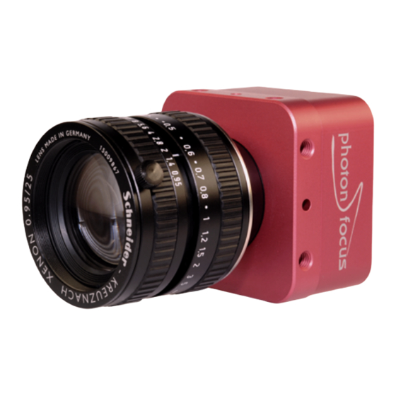
® How to get started (CameraLink ® The following items are required to operate your Photonfocus 1280 CameraLink camera: • ® • Suitable CameraLink frame grabber card to be installed in the PC. All Photonfocus ® ® CameraLink cameras are fully compatible with the CameraLink standard 1.1 and later. - Page 14 ® 3 How to get started (CameraLink Figure 3.1: Camera with protective cap and lens. To choose a lens, see the Lens Finder in the ’Support’ area at www.photonfocus.com. ® Connect the camera to the frame grabber with a suitable CameraLink cable (see Fig.
- Page 15 Check the correct supply voltage and polarity! Do not exceed the maximum operating voltage of +12V DC (± 10%). Connect the power supply to the camera (see Fig. 3.2). The status LED on the rear of the camera will light red for a short moment, and then flash green.
- Page 16 ® 3 How to get started (CameraLink Figure 3.4: PFRemote start window...
-
Page 17: Product Specification
Product Specification 4.1 Introduction The Photonfocus 1280 CMOS camera series is built around the CMOS image sensors EV76C560 and EV76C661 from E2V, that provide a resolution of 1280 x 1024. The cameras are optimized for low light conditions and there are standard monochrome, NIR enhanced monochrome (I) and colour (C) models. -
Page 18: Feature Overview
4 Product Specification 4.2 Feature Overview The general specification and features of the camera are listed in the following sections. The detailed description of the camera features is given in Chapter 5. ® Characteristics Photonfocus 1280 CameraLink Series ® Interface CameraLink base configuration Camera Control... -
Page 19: Available Camera Models
4.3 Available Camera Models Please check the availability of a specific camera model on our website www.photonfocus.com. Name Sensor Resolution Color MV1-D1280-120-CL-10 EV76C560ABT-EQV 1280 x 1024 65 fps MV1-D1280C-120-CL-10 EV76C560ACT-EQV 1280 x 1024 65 fps MV1-D1280I-120-CL-10 EV76C661ABT 1280 x 1024 65 fps Table 4.2: Available Photonfocus 1280 camera models 4.3 Available Camera Models... -
Page 20: Technical Specification
4 Product Specification 4.4 Technical Specification D-120 Sensor (standard monochrome & colour) E2V EV76C560 Sensor (NIR monochrome) E2V EV76C661 Technology CMOS active pixel Scanning system progressive scan Optical format / diagonal 1/1.8” (8.7 mm diagonal) Resolution 1280 x 1024 pixels Pixel size 5.3 µm x 5.3 µm Active optical area... - Page 21 ® Photonfocus 1280 CameraLink Series Operating temperature / moisture 0°C ... 50°C / 20 ... 80 % Storage temperature / moisture -25°C ... 60°C / 20 ... 95 % Camera power supply +12 V DC (± 10 %) Trigger signal input range +5 ..
-
Page 22: Rgb Bayer Pattern Filter
4 Product Specification The colour cameras are equipped with a infra-red cut-off filter to avoid false colours arising when an infra-red component is present in the illumination. Fig. 4.3 shows the transmssion curve of the cut-off filter. Figure 4.3: Transmission curve of the cut-off filter in the Photonfocus 1280 colour camera models 4.5 RGB Bayer Pattern Filter Fig. -
Page 23: Frame Grabber Relevant Configuration
4.6 Frame Grabber relevant Configuration The parameters and settings, which are essential to configure the frame grabber are shown in Table 4.5. D-120 Pixel Clock 60 MHz Number of Taps Greyscale resolution 10 bit / 8 bit Start Pause 6 clock cycles Line Pause 248 ... - Page 24 4 Product Specification...
-
Page 25: Functionality
Functionality This chapter serves as an overview of the camera configuration modes and explains camera features. The goal is to describe what can be done with the camera. The setup of the cameras is explained in later chapters. 5.1 Reduction of Image Size With the Photonfocus 1280 camera series there are several possibilities to focus on the interesting parts of an image, thus reducing the data rate and increasing the frame rate. -
Page 26: Flip Image, Mirror Image
5 Functionality 5.1.2 Flip Image, Mirror Image Flip and mirror image are available to allow the application to use any type of lens (with or without mirror). Flip and mirror image is applied prior to the ROI configuration. Flip- and mirror image feature is not available in the colour cameras. 5.1.3 Decimation (monochrome cameras) Decimation reduces the number of pixels in x- and y-direction. - Page 27 ( 0 , 0 ) R O I m a x m a x Figure 5.2: Decimation and ROI Figure 5.3: Image example of decimation 3 R O I w i t h o u t d e c i m a t i o n R O I w i t h d e c i m a t i o n Figure 5.4: Example of decimation 2 on image of injection needle 5.1 Reduction of Image Size...
-
Page 28: Decimation (Colour Cameras)
5 Functionality 5.1.4 Decimation (colour cameras) Decimation reduces the number of pixels in y-direction by skipping rows and in x-direction by skipping columns. Decimation in colour cameras is slightly different from the monochrome cameras, because the order of the Bayer pattern must be maintained. Beginning from the first row, always two rows are read out and then an even number of rows are skipped, when decimation in y is configured. - Page 29 Y D e c i m a t i o n = 2 Y D e c i m a t i o n = 3 s k i p s k i p X D e c i m a t i o n = 2 X D e c i m a t i o n = 3 W i n d o w .
-
Page 30: Maximal Frame Rate
5 Functionality pixel value will be saturated at 1023 if it exceeds this limit. A shift value of 2 will output 11 to 2 of the binned data. Figure Fig. 5.8 shows the relation between the shift value and the output data alignment. -
Page 31: Trigger And Strobe
Sequential Read out Timing The camera supports only the sequential read out timing. It means the exposure is started after the read out of the previous frame (see Fig. 5.9). The maximal frame rate is in this case (values are given in Table 5.5): MaxFrameRate = 1 / (ExposureTime + TReadoutDel + ReadoutTime) The ReadoutTime is the height of the ROI multiplied by the read out time of one row (see Table 5.5). -
Page 32: Trigger Timing
5 Functionality trigger is generated by the frame grabber board and sent on the CC1 signal through the ® CameraLink interface. Some frame grabbers allow the connection external trigger devices through an I/O card. A schematic diagram of this setup is shown in Fig. 5.11. I/O Trigger In the I/O trigger mode, the trigger signal is applied directly to the camera by the power supply connector (via an optocoupler). - Page 33 M a c h i n e V i s i o n S y s t e m F l a s h T T L C a m e r a 1 C a m e r a L i n k F r a m e G r a b b e r P o w e r D a t a C a m e r a L i n k...
-
Page 34: Trigger Delay
5 Functionality The trigger pulse from the internal camera control starts also the strobe control state machines. The strobe can be delayed by t with an internal counter which can be controlled by strobe delay the customer via software settings. The strobe offset delay t results then from the strobe delay synchronous design of the FPGA state machines. - Page 35 e x t e r n a l t r i g g e r p u l s e i n p u t t r i g g e r a f t e r i s o l a t o r d - i s o - i n p u t t r i g g e r p u l s e i n t e r n a l c a m e r a c o n t r o l j i t t e r...
-
Page 36: Trigger Timing Values
5 Functionality 5.2.6 Trigger timing values Table 5.7 shows the values of the trigger timing parameters. D-120 D-120 Timing Parameter Minimum Maximum 45 ns 60 ns d iso input 16.6 ns jitter 0.279 s trigger delay 0.279 s burst trigger delay depends on camera settings 0.279 s burst period time... -
Page 37: Software Trigger
5.2.7 Software Trigger The software trigger enables to emulate an external trigger pulse by the camera software through the serial data interface. It works with both burst mode enabled and disabled. As soon as it is performed via the camera software, it will start the image acquisition(s), depending on the usage of the burst mode and the burst configuration. -
Page 38: Data Path Overview
5 Functionality 5.3 Data Path Overview The data path is the path of the image from the output of the image sensor to the output of the camera. The sequence of blocks is shown in figure Fig. 5.15. I m a g e S e n s o r D i g i t a l O f f s e t D i g i t a l G a i n D i g i t a l F i n e G a i n... -
Page 39: Gain And Offset
5.4 Gain and Offset There are three different gain settings on the camera: Analog Gain Analog gain on the image sensor. Available values: 1x, 1.5x, 2x, 3x, 4x, 6x and 8x. Note that Digital Offset is applied after the Analog Gain. Gain (Digital Fine Gain) Digital fine gain accepts fractional values from 0.01 up to 15.99. -
Page 40: Gain
5 Functionality y = f ( x ) m a x m a x Figure 5.16: Commonly used LUT transfer curves 5.5.1 Gain The ’Gain’ mode performs a digital, linear amplification with clamping (see Fig. 5.17). It is configurable in the range from 1.0 to 4.0 (e.g. 1.234). Grey level transformation −... -
Page 41: Gamma
5.5.2 Gamma The ’Gamma’ mode performs an exponential amplification, configurable in the range from 0.4 to 4.0. Gamma > 1.0 results in an attenuation of the image (see Fig. 5.18), gamma < 1.0 results in an amplification (see Fig. 5.19). Gamma correction is often used for tone mapping and better display of results on monitor screens. -
Page 42: User-Defined Look-Up Table
5 Functionality 5.5.3 User-defined Look-up Table In the ’User’ mode, the mapping of input to output grey levels can be configured arbitrarily by the user. There is an example file in the PFRemote folder. LUT files can easily be generated with a standard spreadsheet tool. - Page 43 ( 0 , 0 ) N N N N O O L U T 0 O L U T 1 O m a x m a x Figure 5.21: Overlapping Region-LUT example ( 0 , 0 )
- Page 44 5 Functionality Fig. 5.23 shows the application of the Region-LUT to a camera image. The original image without image processing is shown on the left-hand side. The result of the application of the Region-LUT is shown on the right-hand side. One Region-LUT was applied on a small region on the lower part of the image where the brightness has been increased.
-
Page 45: Crosshairs
5.6 Crosshairs 5.6.1 Functionality The crosshairs inserts a vertical and horizontal line into the image. The width of these lines is one pixel. The grey level is defined by a 12 bit value (0 means black, 4095 means white). This allows to set any grey level to get the maximum contrast depending on the acquired image. - Page 46 5 Functionality The x- and y-positon is absolute to the sensor pixel matrix. It is independent on the ROI configuration. Figure Fig. 5.25 shows two situations of the crosshairs configuration. The same ROI settings is used in both situations. The crosshairs however is set differently. The crosshairs is not seen in the image on the right, because the x- and y-position is set outside the MROI region.
-
Page 47: Test Images
5.7 Test Images Test images are generated in the camera FPGA, independent of the image sensor. They can be used to check the transmission path from the camera to the frame grabber. Independent from the configured grey level resolution, every possible grey level appears the same number of times in a test image. - Page 48 5 Functionality Figure 5.27: LFSR (linear feedback shift register) test image non-flat histogram (Fig. 5.29) indicates problems, that may be caused either by the cable, by the connectors or by the frame grabber. ® A possible origin of failure message can be caused by the CameraLink cable which exceeds the maximum length.
- Page 49 ® Some thinner CameraLink cables have a predefined direction. In these cables not all twisted pairs are separately shielded to meet the RS644 standard. These pairs are used for the transmission of the RX/TX and for the CC1 to CC4 low frequency control signals.
-
Page 50: Configuration Interface (Cameralink )
5 Functionality ® 5.8 Configuration Interface (CameraLink ® A CameraLink camera can be controlled by the user via a RS232 compatible asynchronous ® serial interface. This interface is contained within the CameraLink interface as shown in Fig. 5.30 and is physically not directly accessible. Instead, the serial communication is usually routed through the frame grabber. -
Page 51: Hardware Interface
Hardware Interface 6.1 Connectors ® 6.1.1 CameraLink Connector ® The CameraLink cameras are interfaced to external components via ® ® • a CameraLink connector, which is defined by the CameraLink standard as a 26 pin, 0.5" Mini Delta-Ribbon (MDR) connector to transmit configuration, image data and trigger. •... -
Page 52: Trigger And Strobe Signals
6 Hardware Interface 6.1.3 Trigger and Strobe Signals The power connector contains an external trigger input and a strobe output. The trigger input is equipped with a constant current diode which limits the current of the optocoupler over a wide range of voltages. Trigger signals can thus directly get connected with the input pin and there is no need for a current limiting resistor, that depends with its value on the input voltage. -
Page 53: Status Indicator (Cameralink Cameras)
STROBE_VDD Pull-up Resistor 15 V > 3.9 kOhm 10 V > 2.7 kOhm > 2.2 kOhm > 1.8 kOhm > 1.0 kOhm Table 6.1: Pull-up resistor for strobe output and different voltage levels ® 6.1.4 Status Indicator (CameraLink cameras) A dual-color LED on the back of the camera gives information about the current status of the ®... - Page 54 6 Hardware Interface ® Serial communication: A CameraLink camera can be controlled by the user via a RS232 compatible asynchronous serial interface. This interface is contained within the ® CameraLink interface and is physically not directly accessible. Refer to Section 5.8 for more information.
-
Page 55: The Pfremote Control Tool
The PFRemote Control Tool 7.1 Overview PFRemote is a graphical configuration tool for Photonfocus cameras. The latest release can be downloaded from the support area of www.photonfocus.com. All Photonfocus cameras can be either configured by PFRemote, or they can be programmed with custom software using the PFLib SDK ([PFLIB]). -
Page 56: Graphical User Interface (Gui)
7 The PFRemote Control Tool • PFCAM.DLL: The main DLL file that handles camera detection, switching to specific camera DLL and provides the interface for the SDK. • ’CAMERANAME’.DLL: Specific camera DLL ® • COMDLL.DLL: Communication DLL. This COMDLL is not necessarily CameraLink specific, but ®... -
Page 57: Ports, Device Initialization
7.5.2 Ports, Device Initialization After starting PFRemote, the main window as shown in Fig. 7.2 will appear. In the PortBrowser in the upper left corner you will see a list of supported ports. Depending on the configuration, your port names may differ, and not every port may be functional. -
Page 58: Main Buttons
7 The PFRemote Control Tool 7.5.3 Main Buttons The buttons on the right side of the configuration dialog store and reset the camera configuration. Figure 7.3: Main buttons Reset: Reset the camera and load the default configuration. Store as defaults: Store the current configuration in the camera flash memory as the default configuration. -
Page 59: Graphical User Interface (Gui)
Graphical User Interface (GUI) 8.1 MV1-D1280-120 GUI description This section describes the parameters of the following camera: • MV1-D1280-120-CL, CameraLink interface • MV1-D1280I-120-CL, CameraLink interface • MV1-D1280C-120-CL, CameraLink interface The following sections are grouped according to the tabs in the configuration dialog. Figure 8.1: Frame rate and average value indication Frame Rate [fps]: Shows the actual frame rate of the camera in frames per second. -
Page 60: Exposure
8 Graphical User Interface (GUI) 8.1.1 Exposure This tab contains exposure settings. Figure 8.2: Exposure panel Exposure Exposure time [ms]: Configure the exposure time in milliseconds. Constant Frame Rate: When the Constant Frame Rate (CFR) is switched on, the frame rate (number of frames per second) can be varied from almost 0 up to the maximum frame rate. -
Page 61: Window
8.1.2 Window This tab contains the settings for the region of interest. Figure 8.3: Window panel Region of Interest The region of interest (ROI) is defined as a rectangle (X, Y), (W, H) where X: X - coordinate, starting from 0 in the upper left corner. Y: Y - coordinate, starting from 0 in the upper left corner. - Page 62 8 Graphical User Interface (GUI) Flip- & Mirror-Image is not available in colour camera models. Decimation Decimation reduces the number of pixels in y-direction. Decimation can also be used together with a ROI or MROI. Decimation in y-direction transfers every n-th row only and directly results in reduced read-out time and higher frame rate respectively.
-
Page 63: Trigger
8.1.3 Trigger This tab contains trigger and strobe settings. Figure 8.4: Trigger panel Trigger Trigger Source: Free running: The camera continuously delivers images with a certain configurable frame rate. Interface Trigger: The Trigger signal is applied to the camera by the CameraLink frame grabber or the USB interface respectively. - Page 64 8 Graphical User Interface (GUI) Enable Burst Trigger: Enables the burst trigger feature. Number of Burst Triggers: Set the number of burst triggers. Burst Trigger Period [ms]: Set the time between the burst in milliseconds. Burst Trigger Delay [ms]: Set the delay of the burst trigger in milliseconds. Strobe The camera generates a strobe output signal that can be used to trigger a strobe.
-
Page 65: Data Output
8.1.4 Data Output This tab contains image data settings. Figure 8.5: Data output panel Output Mode Output Mode: Normal: Normal mode. LFSR: Test image. Linear feedback shift register (pseudo-random image). The pattern depends on the grey level resolution. Ramp: Test image. Values of pixel are incremented by 1, starting at each row. The pattern depends on the grey level resolution. - Page 66 8 Graphical User Interface (GUI) 4x: Digital gain 4. 8x: Digital gain 8. Digital Offset: Substracts an offset from the data. Only available in gain mode. Analog Gain: 1x: No analog gain (gain 1.0x). 1.5x: Analog gain 1.5x. 2x: Analog gain 2.0x. 3x: Analog gain 3.0x.
-
Page 67: Lut (Look-Up-Table)
8.1.5 LUT (Look-Up-Table) This tab contains LUT settings. Figure 8.6: LUT panel Grey level transformation is remapping of the grey level values of an input image to new values which transform the image in some way. The look-up-table (LUT) is used to convert the greyscale value of each pixel in an image into another grey value. - Page 68 8 Graphical User Interface (GUI) Region LUT Both LUT can be configured with ROI vlaues. The LUT is only working inside the the ROI values. Overlapping is possible. LUT0 has higher priority. Enable Region LUT: Enable the region LUT functionality. Region of LUT: X: X - coordinate of region LUT, starting from 0 in the upper left corner.
-
Page 69: Binning
8.1.6 Binning This tab contains the binning settings. Figure 8.7: Binning panel Binning Enable Binning: Enables the binning feature. Binning Bitshift: 0: Sends the 10 LSB of the 12bit binned pixel data. Result is saturated at 1023 (@ 10 bit). 1: Sends bits 10 to 1 of the 12bit binned pixel data. - Page 70 8 Graphical User Interface (GUI) Figure 8.8: Info panel Camera Info Camera name: Name of the connected camera. Typecode: Type code of the connected camera. Serial: Serial number of the connected camera. FPGA Revision: Firmware revision of built-in FPGA of the connected camera. uC Revision: Firmware revision of built-in microcontroller of the connected camera.
- Page 71 Image: The image counter is a 24 bit real-time counter and is incremented by 1 for every new image. Missed Trigger: This is a counter for trigger pulses that were blocked because the trigger pulse was received during image exposure or readout. In free-running mode it counts all pulses received from interface trigger or from I/O trigger interface.
- Page 72 8 Graphical User Interface (GUI)
-
Page 73: Mechanical Considerations
Mechanical Considerations 9.1 Mechanical Interface During storage and transport, the camera should be protected against vibration, shock, moisture and dust. The original packaging protects the camera adequately from vibration and shock during storage and transport. Please either retain this packaging for possible later use or dispose of it according to local regulations. - Page 74 9 Mechanical Considerations...
-
Page 75: Warranty
Warranty The manufacturer alone reserves the right to recognize warranty claims. 10.1 Warranty Terms The manufacturer warrants to distributor and end customer that for a period of two years from the date of the shipment from manufacturer or distributor to end customer (the "Warranty Period") that: •... - Page 76 10 Warranty...
-
Page 77: References
References All referenced documents can be downloaded from our website at www.photonfocus.com. ® CL CameraLink Specification, January 2004 SW002 PFLib Documentation, Photonfocus, August 2005 AN007 Application Note "Camera Acquisition Modes", Photonfocus, March 2004 AN008 Application Note "Photometry versus Radiometry", Photonfocus, December 2004 AN010 Application Note "Camera Clock Concepts", Photonfocus, July 2004 ®... - Page 78 11 References...
-
Page 79: A Pinouts
Pinouts A.1 Power Supply Connector The power supply plugs are available from Binder connectors at www.binder-connector.de. Fig. A.2 shows the power supply plug from the solder side. The pin assignment of the power supply plug is given in Table A.2. It is extremely important that you apply the appropriate voltages to your camera. -
Page 80: Cameralink Connector
A Pinouts " Figure A.2: Power supply plug, 7-pole (rear view of plug, solder side) I/O Type Name Description +12 V DC (± 10%) Ground RESERVED Do not connect STROBE-VDD +5 .. +15 V DC STROBE Strobe control (opto-isolated) TRIGGER External trigger (opto-isolated), +5 .. - Page 81 Name Description SHIELD Shield ® N_XD0 Negative LVDS Output, CameraLink Data D0 ® N_XD1 Negative LVDS Output, CameraLink Data D1 ® N_XD2 Negative LVDS Output, CameraLink Data D2 ® N_XCLK Negative LVDS Output, CameraLink Clock ® N_XD3 Negative LVDS Output, CameraLink Data D3 P_SERTOCAM Positive LVDS Input, Serial Communication to the camera...
- Page 82 A Pinouts...
-
Page 83: Revision History
Revision History Revision Date Changes May 2013 First version May 2013 Bayer pattern description modified...
Need help?
Do you have a question about the CameraLink MV1-D1280 and is the answer not in the manual?
Questions and answers