
Related Manuals for Photon Focus MV1-D1280-L01-3D05 Series


Summary of Contents for Photon Focus MV1-D1280-L01-3D05 Series
- Page 1 Photonfocus MV1-D1280-L01-3D05 Camera Series CMOS camera with GigE interface MAN073 12/2016 V1.0...
- Page 2 All information provided in this manual is believed to be accurate and reliable. No responsibility is assumed by Photonfocus AG for its use. Photonfocus AG reserves the right to make changes to this information without notice. Reproduction of this manual in whole or in part, by any means, is prohibited without prior permission having been obtained from Photonfocus AG.
-
Page 3: Table Of Contents
Contents 1 Preface 1.1 IMPORTANT NOTICE! ........1.2 About Photonfocus . - Page 4 CONTENTS 5.2.12 Absolute Coordinates ....... . . 47 5.3 Reduction of Image Size ........48 5.3.1 Region of Interest (ROI) (2Donly mode) .
- Page 5 CONTENTS 7.2.5 Save camera setting to a file ......92 7.2.6 Get feature list of camera ......93 7.3 Pleora SDK .
- Page 6 CONTENTS MAN073 12/2016 V1.0 6 of 117...
-
Page 7: Preface
Preface 1.1 IMPORTANT NOTICE! READ THE INSTRUCTIONS FOR USE BEFORE OPERATING THE CAMERA STORE THE INSTRUCTIONS FOR USE FOR FURTHER READING Photonfocus AG Bahnhofplatz 10 CH-8853 Lachen SZ Switzerland www.photonfocus.com info@photonfocus.com +41 – 55 451 00 00 MAN073 12/2016 V1.0 7 of 117... -
Page 8: About Photonfocus
1 Preface 1.2 About Photonfocus The Swiss company Photonfocus is one of the leading specialists in the development of CMOS image sensors and corresponding industrial cameras for machine vision. Photonfocus is dedicated to making the latest generation of CMOS technology commercially available. -
Page 9: Legend
1.6 Legend Photonfocus can not be held responsible for any technical or typographical er- rors. 1.6 Legend In this documentation the reader’s attention is drawn to the following icons: Important note, additional information Important instructions General warning, possible component damage hazard Warning, electric shock hazard Warning, fire hazard MAN073 12/2016 V1.0... - Page 10 1 Preface MAN073 12/2016 V1.0 10 of 117...
-
Page 11: Introduction
Introduction This manual describes the Photonfocus 3D camera series that have a Gigabit Ethernet (GigE) interface and are based on the image sensor LUX1310 sensors from Luxima Technology. A list of all cameras covered in this manual is shown in Table 4.2. The term MV1-D1280-L01-3D05 is used in this manual to denote all available cameras of this series. - Page 12 2 Introduction MAN073 12/2016 V1.0 12 of 117...
-
Page 13: How To Get Started (3D Gige G2)
How to get started (3D GigE G2) 3.1 Introduction This guide shows you: • How to install the required hardware (see Section 3.2) • How to install the required software (see Section 3.3) and configure the Network Adapter Card (see Section 3.4 and Section 3.5) •... - Page 14 3 How to get started (3D GigE G2) Do not bend GigE cables too much. Excess stress on the cable results in transmis- sion errors. In robots applications, the stress that is applied to the GigE cable is especially high due to the fast movement of the robot arm. For such applications, special drag chain capable cables are available.
-
Page 15: Software Installation
3.3 Software Installation A suitable power supply can be ordered from your Photonfocus dealership. Connect the power supply to the camera (see Fig. 3.1). 3.3 Software Installation This section describes the installation of the required software to accomplish the tasks described in this chapter. - Page 16 3 How to get started (3D GigE G2) Figure 3.3: PFInstaller components choice MAN073 12/2016 V1.0 16 of 117...
-
Page 17: Network Adapter Configuration
3.4 Network Adapter Configuration 3.4 Network Adapter Configuration This section describes recommended network adapter card (NIC) settings that enhance the performance for GigEVision. Additional tool-specific settings are described in the tool chapter. Open the Network Connections window (Control Panel -> Network and Internet Connections ->... - Page 18 3 How to get started (3D GigE G2) By default, Photonfocus GigE Vision cameras are configured to obtain an IP address automatically. For this quick start guide it is recommended to configure the network adapter to obtain an IP address automatically. To do this, select Internet Protocol (TCP/IP) (see Fig.
- Page 19 3.4 Network Adapter Configuration Open again the Local Area Connection Properties window (see Fig. 3.4) and click on the Configure button. In the window that appears click on the Advanced tab and click on Jumbo Frames in the Settings list (see Fig. 3.6). The highest number gives the best performance. Some tools however don’t support the value 16128.
- Page 20 3 How to get started (3D GigE G2) No firewall should be active on the network adapter where the Photonfocus GigE camera is connected. If the Windows Firewall is used then it can be switched off like this: Open the Windows Firewall configuration (Start -> Control Panel -> Network and Internet Connections ->...
-
Page 21: Network Adapter Configuration For Pleora Ebus Sdk
3.5 Network Adapter Configuration for Pleora eBUS SDK 3.5 Network Adapter Configuration for Pleora eBUS SDK Open the Network Connections window (Control Panel -> Network and Internet Connections -> Network Connections), right click on the name of the network adapter where the Photonfocus camera is connected and select Properties from the drop down menu that appears. - Page 22 3 How to get started (3D GigE G2) Figure 3.9: PF_GEVPlayer start screen Click on the Select / Connect button in the PF_GEVPlayer . A window with all detected devices appears (see Fig. 3.10). If your camera is not listed then select the box Show unreachable GigE Vision Devices.
- Page 23 3.6 Getting started Figure 3.11: GEV Device Selection Procedure displaying GigE Vision Device Information Select a valid IP address for selected camera (see Fig. 3.12). There should be no exclamation mark on the right side of the IP address. Click on Ok in the Set IP Address dialog.
- Page 24 3 How to get started (3D GigE G2) Figure 3.13: PF_GEVPlayer is readily configured If no images can be grabbed, close the PF_GEVPlayer and adjust the Jumbo Frame parameter (see Section 3.3) to a lower value and try again. Figure 3.14: PF_GEVPlayer displaying live image stream Check the status LED on the rear of the camera.
- Page 25 3.6 Getting started Figure 3.15: Control settings on the camera To modify the exposure time scroll down to the AcquisitionControl control category (bold title) and modify the value of the ExposureTime property. MAN073 12/2016 V1.0 25 of 117...
- Page 26 3 How to get started (3D GigE G2) MAN073 12/2016 V1.0 26 of 117...
-
Page 27: Product Specification
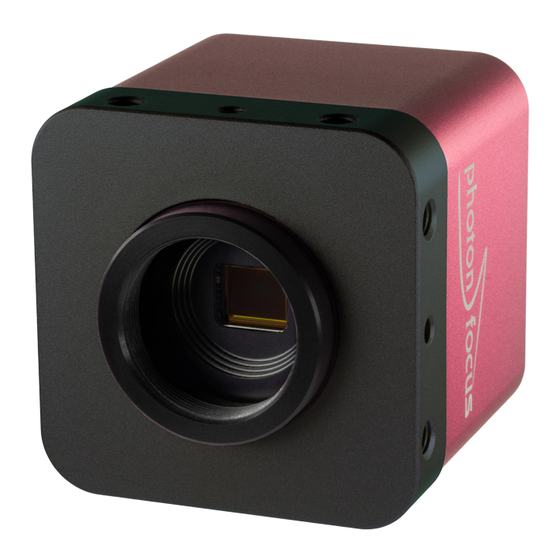
Product Specification 4.1 Introduction This manual describes the Photonfocus MV1-D1280-L01-3D05 camera series. The cameras have a Gigabit Ethernet interface and are optimized for very high speed laser triangulation applications with 43700 profiles/s (at 1280 x 16 pixels resolution). The MV1-D1280-L01-3D05 camera contains a 1.3 megapixel CMOS image sensor. - Page 28 4 Product Specification L a s e r C a m e r a + o n v e y o r b e l t w i t h o b j e c t s Figure 4.1: Triangulation principle with objects moved on a conveyor belt Figure 4.2: Photonfocus MV1-D1280-L01-3D05 camera series MAN073 12/2016 V1.0 28 of 117...
-
Page 29: Feature Overview
4.2 Feature Overview 4.2 Feature Overview The general specification and features of the camera are listed in the following sections. The detailed description of the camera features is given in Chapter 5. MV1-D1280-L01-3D05-1280 Interface Gigabit Ethernet, GigE Vision, GenICam, Shaft Encoder Camera Control GigE Vision Suite / PF 3D Suite Trigger Modes... -
Page 30: Technical Specification
4 Product Specification 4.4 Technical Specification MV1-D1280-L01-3D05-1280 Sensor Luxima Technology LUX1310 Technology CMOS active pixel Scanning system progressive scan Optical format / diagonal 2/3” (10.82 mm diagonal) Sensor resolution 1280 x 1024 pixels Pixel size 6.6 m x 6.6 m Active optical area 8.45 mm x 6.76 mm Full well capacity... -
Page 31: Heat Dissipation
4.4 Technical Specification MV1-D1280-L01-3D05 cameras Operating temperature 0°C ... 40°C / 20 ... 80 % Storage temperature / moisture -25°C ... 60°C / 20 ... 95 % Operating height <2000 m above sea level Camera power supply +12 V DC (- 10 %) ... +24 V DC (+ 10 %) Trigger signal input range +5 .. -
Page 32: Absolute Maximum Ratings
4 Product Specification 4.4.2 Absolute Maximum Ratings Parameter Value Power Supply Voltage 26.4 V ESD Contact Discharge Power Supply 4 kV ESD Air Discharge Power Supply 8 kV Fast Transients/Bursts Power Supply 2 kV Camera Control Input Signal Voltage Single Ended -30 V ... -
Page 33: Spectral Response
4.4 Technical Specification 4.4.4 Spectral Response Fig. 4.3 shows the quantum efficiency curve of the monochrome LUX1310 sensor from Luxima Technology measured in the wavelength range from 400 nm to 1000 nm. LUX1310 Wavelength [nm] Figure 4.3: Spectral response of the LUX1310 CMOS monochrome image sensors (with micro lenses) MAN073 12/2016 V1.0 33 of 117... - Page 34 4 Product Specification MAN073 12/2016 V1.0 34 of 117...
-
Page 35: Functionality
Functionality 5.1 Introduction This chapter serves as an overview of the camera configuration modes and explains camera features. The goal is to describe what can be done with the camera. The setup of the MV1-D1280-L01-3D05 cameras is explained in later chapters. 5.2 3D Features 5.2.1 Overview The MV1-D1280-L01-3D05 cameras contain an accurate laser line detector for laser... - Page 36 5 Functionality Triangulation Setup 1 In this setup the camera looks with the viewing angle on the laser line projected from the top. A larger angle leads to a higher resolution. With larger angles the range of height is reduced. Small angles have the benefit of little occlusions. Line Laser Camera Figure 5.1: Triangulation setup 1...
- Page 37 5.2 3D Features Triangulation Setup 3 In this setup the laser line generator and the camera are placed in a more reflecting configuration. This gives more signal and could be used for dark or matte surfaces. In case of reflecting surfaces there is only a little amount of scattering which can be used as signal for triangulation.
-
Page 38: Laser Line Detection
5 Functionality 5.2.3 Laser Line Detection The laser line detector takes a threshold value as its input. All pixels with grey value below the threshold value will be ignored. This filters out the image background. A second threshold value (WidthThreshold) is used in the calculation of the laser line width (see also Fig. -
Page 39: Laser Line Detection Algorithm
5.2 3D Features 5.2.4 Laser Line Detection Algorithm Structured light based systems crucially rely on an accurate determination of the position of the laser line. A Center Of Gravity (COG) algorithm is implemented in the MV1-D1280-L01-3D05 camera series. A user-selectable threshold is used to separate the image background from the laser line. - Page 40 5 Functionality STAT value: the status (value) of some parameters and internal registers are placed here. The status information is described in Section 5.8.2. In every pixel (column) 4 bits of this status information send, starting with the LSB in the first column. B i t s ! D r o w D e s c r i p t i o n...
- Page 41 5.2 3D Features fractional part is calculated from the 4 LSB of 3D row 1: 0b1100 = 0xc. This value must be divided by 16: 0xc / 16 = 0.75. The laser line width is 10 pixels (6 LSB of 3D row 2). The LL_HEIGHT value is in this case 8 (=4 MSB of 3D row 3).
-
Page 42: Transmitted Data In 2D&3D Mode
5 Functionality 5.2.8 Transmitted data in 2D&3D mode The transmitted image in 2D&3D mode is shown in Fig. 5.10. The data is transmitted in the following order: • Raw image • 3D data Resulting height in 2D&3D mode is: Hres = Peak0_3DH + 4 (if DataFormat3D=3 or 4), or Hres = Peak0_3DH + 2 (if DataFormat3D=2) R a w i m a g e P e a k 0 _ 3 D H... -
Page 43: Frame Combine
5.2 3D Features 5.2.10 Frame Combine Very high frame rates, that are well over 1000 fps, can be achieved in 3Donly mode. Every frame (image) activates an interrupt in the GigE software which will issue a high CPU load or the frame rate can not be handled at all by an overload of interrupts. - Page 44 5 Functionality FrameCombine_ForceTimeout The transmission of the combined frame is forced by writing to the FrameCombine_ForceTimeout property. When the FrameCombine is finished by a timeout, then the remaining data in the combined frame will be filled with filler data: the first two pixels of every filler row have the values 0xBB (decimal 187) and 0x44 (decimal 68).
-
Page 45: Peak Filter
5.2 3D Features 5.2.11 Peak Filter Peaks that are detected by the laser line detection algorithm can be filtered by applying the parameters described in this section. A filtered peak appears as all 3D data set to 0, which is the same as if no peak occurred. - Page 46 5 Functionality f i l t e r e d : w i d t h t o o b i g f i l t e r e d : w i d t h t o o s m a l l W i d t h T h r e s h o l d T h r e s h o l d y - d i r e c t i o n...
-
Page 47: Absolute Coordinates
5.2 3D Features 5.2.12 Absolute Coordinates The 3D coordinates are given relative to the start of the 3D ROI as a default. When the property Peak0_EnAbsCoordinate is set to True then the 3D coordinates are given relative to the value of the property Peak0_AbsCoordinateBase. This is useful if the 3D-ROI is not kept constant. -
Page 48: Reduction Of Image Size
5 Functionality 5.3 Reduction of Image Size 5.3.1 Region of Interest (ROI) (2Donly mode) This section describes the ROI features in the 2Donly mode where the camera behaves as a standard area scan camera. The maximal frame rate of the 2Donly mode is considerably lower than in the 3Donly mode. -
Page 49: Region Of Interest (Roi) In 3D Modes
5.3 Reduction of Image Size 5.3.2 Region of Interest (ROI) in 3D modes The ROI is determined by the following properties: OffsetX, Width, Peak0_3DY, Peak0_3DH, DataFormat3D. The area for the detection of the laser line is defined by the parameters Peak0_3DY, Peak0_3DH. -
Page 50: Trigger And Strobe
5 Functionality 5.4 Trigger and Strobe 5.4.1 Trigger Source The trigger signal can be configured to be active high or active low by the TriggerActivation (category AcquisitionControl) property. One of the following trigger sources can be used: Free running The trigger is generated internally by the camera. Exposure starts immediately after the camera is ready and the maximal possible frame rate is attained, if AcquisitionFrameRateEnable is disabled. - Page 51 5.4 Trigger and Strobe Figure 5.16: Trigger source Figure 5.17: Trigger Inputs - Multiple GigE solution MAN073 12/2016 V1.0 51 of 117...
-
Page 52: Acquisition Mode
5 Functionality 5.4.2 Acquisition Mode The available acquisition modes are shown in Table 5.3. The ContinuousRecording and ContinousReadout modes can be used if more than one camera is connected to the same network and need to shoot images si- multaneously. If all cameras are set to Continuous mode, then all will send the packets at same time resulting in network congestion. -
Page 53: Exposure Time Control
5.4 Trigger and Strobe 5.4.3 Exposure Time Control The exposure time is defined by the camera. For an active high trigger signal, the camera starts the exposure with a positive trigger edge and stops it when the programmed exposure time has elapsed. -
Page 54: Trigger Delay
5 Functionality isolated from the camera electronic which leads to an additional delay of t . Table d iso output 5.4 gives an overview over the minimum and maximum values of the parameters. 5.4.4 Trigger Delay The trigger delay is a programmable delay in milliseconds between the incoming trigger edge and the start of the exposure. - Page 55 5.4 Trigger and Strobe A x t e r n a l t r i g g e r p u l s e i n p u t t r i g g e r a f t e r i s o l a t o r d - i s o - i n p u t t r i g g e r p u l s e i n t e r n a l c a m e r a c o n t r o l j i t t e r...
- Page 56 5 Functionality MV1-D1280-L01-3D05 MV1-D1280-L01-3D05 Timing Parameter Minimum Maximum 1.5 s d iso input 65 ns 185 ns d RS422 input 12.5 ns jitter 0.20 s trigger delay 0.20 s burst trigger delay depends on camera settings 0.20 s burst period time (non burst mode) 100 ns duration of 1 row...
-
Page 57: Software Trigger
5.4 Trigger and Strobe 5.4.8 Software Trigger The software trigger enables to emulate an external trigger pulse by the camera software through the serial data interface. It works with both burst mode enabled and disabled. As soon as it is performed via the camera software, it will start the image acquisition(s), depending on the usage of the burst mode and the burst configuration. - Page 58 5 Functionality Double Two triggers are generated on every A/B sequence (see Fig. 5.21). Quad Four triggers are generated on every A/B sequence (see Fig. 5.22). There is a bug in the single A/B trigger mode in some camera revisions (see Ap- pendix B).
- Page 59 5.4 Trigger and Strobe A/B Trigger Debounce A debouncing logic can be enabled by setting ABTriggerDeBounce=True. It is implemented with a watermark value of the EncoderCounter (see Fig. 5.23). Suppose ABTriggerDirection=fwd, then the watermark value is increased with the increments of the EncoderCounter. If EncoderCounter decreases, e.g.
- Page 60 5 Functionality A/B Trigger Divider if ABTriggerDivider>1 then not all internally generated triggers are applied to the camera logic. E.g. If ABTriggerDivider=2, then every second trigger is applied to the camera (see Fig. 5.25). G r a y C o u n t e r E n c o d e r C o u n t e r I n t e r n a l T r i g g e r F w d A p p l i e d T r i g g e r F w d...
-
Page 61: Counter Reset By An External Signal
5.4 Trigger and Strobe By default the Encoder Position is only generated when TriggerMode=On and TriggerSource=ABTrigger. When the property ABTriggerCountAlways=True, then the Encoder Position is generated regardless of the trigger mode. 5.4.10 Counter Reset by an External Signal The image counter and the real time counter (timestamp) (see Section 5.8.1) can be reset by an external signal. -
Page 62: Trigger Acquisition
5 Functionality 5.4.11 Trigger Acquisition The applied trigger can be enabled or disabled by one or two external signals in the TriggerAcquisition mode. This mode works with free-running (internal) trigger and external trigger. The property TriggerAcquisition_Enable enables the TriggerAcquisition mode. Level Triggered Trigger Acquisition The Level Triggered mode is enabled by setting TriggerAcquisition_Mode to Level and TriggerAcquisition_Enable=True. -
Page 63: Strobe Output
5.4 Trigger and Strobe Edge Triggered Trigger Acquisition The Edge Triggered mode is enabled by setting TriggerAcquisition_Mode to Edge and TriggerAcquisition_Enable=True. Two signals act as trigger enable (see Fig. 5.29). A rising edge on the start signal enables triggering. A rising edge on the stop signal disables all triggers. The start/stop signals are selected by TriggerAcquisition_StartSource and TriggerAcquisition_StopSource. -
Page 64: Data Path Overview
5 Functionality 5.5 Data Path Overview The data path is the path of the image from the output of the image sensor to the output of the camera. The sequence of blocks is shown in figure Fig. 5.30. 1 m a g e S e n s o r C o l u m n F P N C o r r e c t i o n D i g i t a l O f f s e t... -
Page 65: Column Fpn Correction
5.6 Column FPN Correction 5.6 Column FPN Correction The camera contains a correction to decrease the Column Fixed Pattern Noise (FPN) of the sensor. By default the Column FPN Correction is enabled. The Column FPN Correction of the camera is correctly calibrated at the Photonfocus production facility. -
Page 66: Status Information
5 Functionality Missed trigger counter The missed trigger counter counts trigger pulses that were ignored by the camera because they occurred within the exposure or read-out time of an image. In free-running mode it counts all incoming external triggers (counter width 8 bit / no wrap around). -
Page 67: Laser Test Image
5.9 Laser test image 5.9 Laser test image A Laser Test Image has been added that resembles a moving laser line (see Fig. 5.31) and it is placed just before the peak detection. Therefore it can be used to test if the 3D data is correctly processed during application development. -
Page 68: Ramp
5 Functionality 5.10.1 Ramp Depending on the configured grey level resolution, the ramp test image outputs a constant pattern with increasing grey level from the left to the right side (see Fig. 5.32). Figure 5.32: Ramp test images: 8 bit output 5.10.2 LFSR The LFSR (Linear Feedback Shift Register) test image outputs a constant pattern with a pseudo-random grey level sequence containing every possible grey level that is repeated for... -
Page 69: Troubleshooting Using The Lfsr
5.10 Test Images 5.10.3 Troubleshooting using the LFSR To control the quality of your complete imaging system enable the LFSR mode, set the camera window to 1024 x 1024 pixels (x=0 and y=0) and check the histogram. The camera window can also be set to a multiple of this resolution (e.g. - Page 70 5 Functionality MAN073 12/2016 V1.0 70 of 117...
-
Page 71: Hardware Interface
Hardware Interface 6.1 GigE Connector The GigE cameras are interfaced to external components via • an Ethernet jack (RJ45) to transmit configuration, image data and trigger. • a 12 pin subminiature connector for the power supply, Hirose HR10A-10P-12S (female) . The connectors are located on the back of the camera. -
Page 72: Status Indicator (Gige Cameras)
6 Hardware Interface A suitable power supply can be ordered from your Photonfocus dealership. For further details including the pinout please refer to Appendix A. 6.3 Status Indicator (GigE cameras) A dual-color LED on the back of the camera gives information about the current status of the GigE CMOS cameras. -
Page 73: Electrical Characteristics
6.5 Electrical Characteristics 6.5 Electrical Characteristics Parameter Value Camera Power Supply +12 V (-10%) ... +24 V (+10%) Camera Control Input Single Ended +5 V ... +30 V Camera Control Input RS422 Receiver Sensitivity +/- 200 mV Camera Control Input RS422 Maximum Common Mode Range -7 V ... - Page 74 6 Hardware Interface C a m e r a I n t e r n a l P o w e r S u p p l y 2 o w e r S u p p l y P O W E R D C / D C V C C _ 1 D C / D C...
-
Page 75: Power And Ground Connection For Gige H2 Cameras
6.7 Power and Ground Connection for GigE H2 Cameras 6.7 Power and Ground Connection for GigE H2 Cameras The interface electronics is isolated from the camera electronics and the power supply including the line filters and camera case. Fig. 6.3 shows a schematic of the power and ground connections in H2 camera models. -
Page 76: Trigger And Strobe Signals For Gige Cameras
6 Hardware Interface 6.8 Trigger and Strobe Signals for GigE Cameras 6.8.1 Overview The 12-pol. Hirose power connector contains two external trigger inputs, two strobe outputs and two differential inputs (G2 models: RS-422, H2 models: HTL). All inputs and outputs are connected to the Programmable Logic Controller (PLC) (see also Section 6.9) that offers powerful operations. - Page 77 6.8 Trigger and Strobe Signals for GigE Cameras C a m e r a I S O L A T O R R S 4 2 2 I S O _ I N C 0 _ P I S O _ I N C 0 _ N - 1 0 V t o + 1 3 V e x t e n d e d...
- Page 78 6 Hardware Interface C a m e r a I S O L A T O R H T L : i n p u t r a n g e : 1 0 V t o 3 0 V I S O _ I N C 0 _ P I S O _ I N C 0 _ N I S O _ I N C 1 _ P...
-
Page 79: Single-Ended Inputs
6.8 Trigger and Strobe Signals for GigE Cameras 6.8.2 Single-ended Inputs ISO_IN0 and ISO_IN1 are single-ended isolated inputs. The input circuit of both inputs is identical (see Fig. 6.4). Fig. 6.6 shows a direct connection to the ISO_IN inputs. In the camera default settings the PLC is configured to connect the ISO_IN0 to the PLC_Q4 camera trigger input. -
Page 80: Single-Ended Outputs
6 Hardware Interface 6.8.3 Single-ended Outputs ISO_OUT0 and ISO_OUT1 are single-ended isolated outputs. ISO_OUT0 and ISO_OUT1 have different output circuits: ISO_OUT1 doesn’t have a pullup resistor and can be used as additional Strobe out (by adding Pull up) or as controllable switch. Maximal ratings that must not be exceeded: voltage: 30 V, current: 0.5 A, power: 0.5 W. - Page 81 6.8 Trigger and Strobe Signals for GigE Cameras Fig. 6.10 shows the connection from ISO_OUT1 to a LED. 1 2 p o l . H i r o s e C a m e r a C o n n e c t o r ;...
-
Page 82: Differential Rs-422 Inputs (G2 Models)
6 Hardware Interface 6.8.4 Differential RS-422 Inputs (G2 models) ISO_INC0 and ISO_INC1 are isolated differential RS-422 inputs (see also Fig. 6.4). They are connected to a Maxim MAX3098 RS-422 receiver device. Please consult the data sheet of the MAX3098 for connection details. Don’t connect single-ended signals to the differential inputs ISO_INC0 and ISO_INC1 (see also Fig. -
Page 83: I/O Wiring
6.8 Trigger and Strobe Signals for GigE Cameras 6.8.6 I/O Wiring The Photonfocus cameras include electrically isolated inputs and outputs. Take great care when wiring trigger and strobe signals to the camera, specially over big distances (a few meters) and in noisy environments. - Page 84 6 Hardware Interface Common Grounds with Star Wiring Ground loops can be avoided using "star wiring", i.e. the wiring of power and ground connections originate from one "star point" which is typically a power supply. Fig. 6.15 shows a schematic of the star-wiring concept. Fig.
- Page 85 6.8 Trigger and Strobe Signals for GigE Cameras Fig. 6.17 shows an example of how to connect a flash light and a trigger source to the camera using star-wiring. The trigger in this example is generated from a light barrier. Note how the power and ground cables are connected to the same power supply.
- Page 86 6 Hardware Interface An example of improper wiring that causes a ground loop is shown in Fig. 6.18. C o n n e c t i n g C A M _ G N D a n d G r o u n d l o o p I S O _ G N D t h e w r o n g w a y 1 s o l a t o r I S O _ I N...
-
Page 87: Plc Connections
6.9 PLC connections 6.9 PLC connections The PLC (Programmable Logic Controller) is a powerful device where some camera inputs and outputs can be manipulated and software interrupts can be generated. Sample settings and an introduction to PLC are shown in Section 7.10. PLC is described in detail in the document [PLC]. Name Direction Description... - Page 88 6 Hardware Interface MAN073 12/2016 V1.0 88 of 117...
-
Page 89: Software
Software 7.1 Software for MV1-D1280-L01-3D05 Various software packages for Photonfocus the MV1-D1280-L01-3D05 camera series are available on the Photonfocus website: eBUS SDK Contains the Pleora SDK and the Pleora GigE filter drivers. Many examples of the SDK are included. PFInstaller Contains the PF_GEVPlayer, the PF 3D Suite and SDK, a property list for every GigE camera and additional documentation and examples. -
Page 90: Pf_Gevplayer Main Window
7 Software 7.2.1 PF_GEVPlayer main window After connecting the camera (see Chapter 3), the main window displays the following controls (see Fig. 7.1): Disconnect Disconnect the camera Mode Acquisition mode Play Start acquisition Stop Stop acquisition Acquisition Control Mode Continuous, Single Frame or Multi Frame modes. The number of frames that are acquired in Multi Frame mode can be set in the GEV Device Control with AcquisitionFrameCount in the AcquisitionControl category. - Page 91 7.2 PF_GEVPlayer To have a quick overview of the available categories, all categories should be collapsed. The categories of interest can then be expanded again. If the name of the property is known, then the alphabetical view is convenient. If this is the first time that you use a Photonfocus GigE camera, then the visibility should be left to Beginner.
-
Page 92: Display Area
7 Software 7.2.3 Display Area The images are displayed in the main window in the display area. A zoom menu is available when right clicking in the display area. Another way to zoom is to press the Ctrl button while using the mouse wheel. -
Page 93: Get Feature List Of Camera
7.3 Pleora SDK 7.2.6 Get feature list of camera A list of all features of the Photonfocus GigE cameras in HTML format can be found in the GenICam_Feature_Lists sub-directory (in Start -> All Programs -> Photonfocus -> GigE_Tools). Alternatively, the feature list of the connected camera can be retrieved with the PF_GEVPlayer (Tools ->... -
Page 94: Laser Line Detector) Settings
7 Software 7.6 3D (Laser Line Detector) settings This section describes how to the set the 3D properties. These properties are described in Section 5.2. Set threshold value for laser line with property Peak0_Threshold (in category LineFinder/Peak0) (see also note in Section 5.2.3). Set scan area by setting the start row (Peak0_3DY in category LineFinder/Peak0) and the height (Peak0_3DH in category LineFinder/Peak0) (see also Section 5.3.2). -
Page 95: Storing The Calibration In Permanent Memory
7.7 Column FPN Correction When the camera will be run in 3Donly mode, which is required for maximal frame rate, then the following settings should be applied: LineFinder_Mode = Mode_3Donly (category LineFinder), Peak0_3DY = 0 (category LineFinder / Peak0 / Peak0_3D), Peak0_3DH = 1024 (category LineFinder / Peak0 / Peak0_3D, Width = 1280 (category ImageFormatControl), Height = 4 (category ImageFormatControl) If different exposure times will be used, calibrate the camera under the longest... -
Page 96: Permanent Parameter Storage / Factory Reset
7 Software 7.8 Permanent Parameter Storage / Factory Reset The property UserSetSave (in category UserSetControl) stores the current camera settings in the non-volatile flash memory. At power-up these values are loaded. The property UserSetSave (in category UserSetControl) overwrites the current camera settings with the settings that are stored in the flash memory. -
Page 97: Plc Settings
7.10 PLC Settings 7.10 PLC Settings 7.10.1 Introduction The Programmable Logic Controller (PLC) is a powerful tool to generate triggers and software interrupts. A functional diagram of the PLC tool is shown in Fig. 7.4. The PLC tool is described in detail with many examples in the [PLC] manual which is included in the PFInstaller. -
Page 98: Plc Settings For Iso_In0 To Plc_Q4 Camera Trigger
7 Software Identify the PLC notation of the desired input. A table of the PLC mapping is given in Section 6.9. In our example, ISO_IN0 maps to A0 or Line0. Select a Signal Routing Block (SRB) that has a connection to the desired PLC input and connect it to the PLC input. -
Page 99: Plc Settings For A/B Trigger From Differential Inputs
7.10 PLC Settings 7.10.3 PLC Settings for A/B Trigger from differential inputs This settings connects the ISO_INC differential inputs to the A/B camera inputs. ISO_INC0 is mapped to the A signal and ISO_INC1 to the B signal, see Table 7.2 (the visibility in the PF_GEVPlayer must be set to Guru for this purpose). -
Page 100: Plc Settings For A/B Trigger From Single-Ended Inputs
7 Software 7.10.4 PLC Settings for A/B Trigger from single-ended inputs This configuration maps the single-ended inputs to the A/B camera inputs: ISO_IN0 is mapped to the A signal and ISO_IN1 to the B signal see Table 7.3 (the visibility in the PF_GEVPlayer must be set to Guru for this purpose). -
Page 101: Mechanical And Optical Considerations
Mechanical and Optical Considerations 8.1 Mechanical Interface During storage and transport, the camera should be protected against vibration, shock, moisture and dust. The original packaging protects the camera adequately from vibration and shock during storage and transport. Please either retain this packaging for possible later use or dispose of it according to local regulations. -
Page 102: Adjusting The Back Focus
8 Mechanical and Optical Considerations 8.2 Adjusting the Back Focus The back focus of your Photonfocus camera is correctly adjusted in the production of the camera. This section describes the procedure to adjust the back focus if you require that because e.g. you are using a special lens. - Page 103 8.3 Optical Interface Use a high quality, low pressure air duster (e.g. Electrolube EAD400D, pure compressed inert gas, www.electrolube.com) to blow off loose particles. This step alone is usually sufficient to clean the sensor of the most common contaminants. Workshop air supply is not appropriate and may cause permanent damage to the sensor.
- Page 104 8 Mechanical and Optical Considerations Product Supplier Remark EAD400D Airduster Electrolube, UK www.electrolube.com Anticon Gold 9"x 9" Wiper Milliken, USA ESD safe and suitable for class 100 environments. www.milliken.com TX4025 Wiper Texwipe www.texwipe.com Transplex Swab Texwipe Small Q-Tips SWABS Q-tips Hans J.
-
Page 105: Standards Compliance
Standards Compliance 9.1 Directives and General Standards The products described in this manual in the form as delivered are in conformity with the provisions of the following European Directives: • 2014/30/EU Electromagnetic compatibility (EMC) • 2014/35/EU Low Voltage (LVD) • 2011/65/EU Restriction of hazardous substances (RoHS) Conformity to the Directives is assured through the application of the following standards: Emission:... -
Page 106: For Customers In Canada
9 Standards Compliance You are cautioned that any changes or modifications not expressly approved in this manual could void your authority to operate this equipment. The shielded interface cable recommended in this manual must be used with this equipment in order to comply with the limits for a computing device pursuant to Subpart B of Part 15 of FCC Rules. -
Page 107: Warranty
Warranty The manufacturer alone reserves the right to recognize warranty claims. 10.1 Warranty Terms The manufacturer warrants to distributor and end customer that for a period of two years from the date of the shipment from manufacturer or distributor to end customer (the "Warranty Period") that: •... - Page 108 10 Warranty Avoid cleaning the sensor with improper methods. Follow the instructions in the corresponding chapter of this manual. Transport and store the camera in its original packaging only and protect the sensor and the lens mount with a camera body cap. 10.
-
Page 109: Support And Repair
Support and Repair This chapter describes the product support and repair. 11.1 Technical Support First level technical support is given from the sales department of Photonfocus or your local dealer. In case your issue could not be solved in this way Photonfocus support team takes over. The Photonfocus support team is available via email: support@photonfocus.com. - Page 110 11 Support and Repair MAN073 12/2016 V1.0 110 of 117...
-
Page 111: References
References All referenced documents can be downloaded from our website at www.photonfocus.com. GEVQS GEVPlayer Quick Start Guide, Pleora Technologies. Included in eBUS installer. MAN051 Manual "Photonfocus GigE Quick Start Guide", Photonfocus PLC iPORT Programmable Logic Controller Reference Guide, Pleora Technologies. Included in GigE software package. - Page 112 12 References MAN073 12/2016 V1.0 112 of 117...
-
Page 113: A Pinouts
Pinouts A.1 Power Supply Connector The power supply connectors are available from Hirose connectors at www.hirose-connectors.com. Fig. A.1 shows the power supply plug from the solder side. The pin assignment of the power supply plug is given in Table A.2. It is extremely important that you apply the appropriate voltages to your camera. - Page 114 A Pinouts I/O Type Name Description CAMERA_GND Camera GND, 0V CAMERA_PWR Camera Power 12V..24V ISO_OUT0 Default Strobe out, internally Pulled up to ISO_PWR with 4k7 Resistor ISO_INC0_N INC0 differential input (G2: RS-422, H2: HTL), negative polarity ISO_INC0_P INC0 differential input (G2: RS-422, H2: HTL), positive polarity ISO_PWR Power supply 5V..24V for output signals;...
-
Page 115: B Camera Revisions
Camera Revisions B.1 General Remarks This chapter lists differences between the revisions of the camera models. Always the newest camera revision is shipped if not otherwise mentioned by the customer. If a previous version is required then this must be clearly mentionend on the purchase order. The version of your camera is stored in the property uCRevision (in category Info / CameraInfo, set visibility to Expert). -
Page 116: Camera Revisions Mv1-D1280-L01-3D05-1280-G2/H2-8
B Camera Revisions B.3 Camera Revisions MV1-D1280-L01-3D05-1280-G2/H2-8 Item V1.0 Laser Line Detection (COG) 2D&3D mode (Section 5.2.5) 3Donly mode (Section 5.2.5) Peak mirror (Section 5.2.6) DataFormat3D (Section 5.2.7) Frame combine (Section 5.2.10) Peak filter (Section 5.2.11) Absolute coordinates (Section 5.2.12) Standard trigger A/B trigger (Section 5.4.9) External counter reset (Section 5.4.10) -
Page 117: Man073 12/2016 V1.0
Revision History Revision Date Changes December 2016 First version MAN073 12/2016 V1.0 117 of 117...
Need help?
Do you have a question about the MV1-D1280-L01-3D05 Series and is the answer not in the manual?
Questions and answers