
Related Manuals for Photon Focus MV1-R1280-50 Series


Summary of Contents for Photon Focus MV1-R1280-50 Series
- Page 1 Photonfocus MV1-R1280-50 Camera Series Ultra low light CMOS camera with GigE interface MAN066 12/2018 V1.1...
- Page 2 All information provided in this manual is believed to be accurate and reliable. No responsibility is assumed by Photonfocus AG for its use. Photonfocus AG reserves the right to make changes to this information without notice. Reproduction of this manual in whole or in part, by any means, is prohibited without prior permission having been obtained from Photonfocus AG.
-
Page 3: Table Of Contents
Contents 1 Preface 1.1 IMPORTANT NOTICE! ........1.2 About Photonfocus . - Page 4 CONTENTS 5.4 Gain and Offset ........53 5.5 Hotpixel Correction .
- Page 5 CONTENTS 9 Standards Compliance 9.1 Directives and General Standards ......91 9.2 Country-specific Information .
- Page 6 CONTENTS MAN066 12/2018 V1.1 6 of 103...
-
Page 7: Preface
Preface 1.1 IMPORTANT NOTICE! READ THE INSTRUCTIONS FOR USE BEFORE OPERATING THE CAMERA STORE THE INSTRUCTIONS FOR USE FOR FURTHER READING Photonfocus AG Bahnhofplatz 10 CH-8853 Lachen SZ Switzerland www.photonfocus.com info@photonfocus.com +41 – 55 451 00 00 MAN066 12/2018 V1.1 7 of 103... -
Page 8: About Photonfocus
1 Preface 1.2 About Photonfocus The Swiss company Photonfocus is one of the leading specialists in the development of CMOS image sensors and corresponding industrial cameras for machine vision. Photonfocus is dedicated to making the latest generation of CMOS technology commercially available. -
Page 9: Legend
1.6 Legend 1.6 Legend In this documentation the reader’s attention is drawn to the following icons: Important note, additional information Important instructions General warning, possible component damage hazard Warning, electric shock hazard Warning, fire hazard MAN066 12/2018 V1.1 9 of 103... - Page 10 1 Preface MAN066 12/2018 V1.1 10 of 103...
-
Page 11: Introduction
Introduction 2.1 MV1-R1280 Introduction The Photonfocus MV1-R1280 camera series is built around a ultra-low noise CMOS image sensor with a high dynamic range. The image sensor uses an innovative integration mode and an advanced analog to digital conversion (ADC) to achieve a read out noise of less than 1e . Fig. - Page 12 2 Introduction MAN066 12/2018 V1.1 12 of 103...
-
Page 13: How To Get Started (Gige G2)
How to get started (GigE G2) 3.1 Introduction This guide shows you: • How to install the required hardware (see Section 3.2) • How to install the required software (see Section 3.3) and configure the Network Adapter Card (see Section 3.4 and Section 3.5) •... - Page 14 3 How to get started (GigE G2) Remove the Photonfocus GigE camera from its packaging. Please make sure the following items are included with your camera: • Power supply connector • Camera body cap If any items are missing or damaged, please contact your dealership. Connect the camera to the GigE interface of your PC with a GigE cable of at least Cat 5E or - t h e r n e t J a c k ( R J 4 5 ) P o w e r S u p p l y...
-
Page 15: Software Installation
3.3 Software Installation 3.3 Software Installation This section describes the installation of the required software to accomplish the tasks described in this chapter. Install the latest drivers for your GigE network interface card. Download the latest eBUS SDK installation file from the Photonfocus server. You can find the latest version of the eBUS SDK on the support (Software Down- load) page at www.photonfocus.com. - Page 16 3 How to get started (GigE G2) Figure 3.3: PFInstaller components choice MAN066 12/2018 V1.1 16 of 103...
-
Page 17: Network Adapter Configuration
3.4 Network Adapter Configuration 3.4 Network Adapter Configuration This section describes recommended network adapter card (NIC) settings that enhance the performance for GigEVision. Additional tool-specific settings are described in the tool chapter. Open the Network Connections window (Control Panel -> Network and Internet Connections ->... - Page 18 3 How to get started (GigE G2) By default, Photonfocus GigE Vision cameras are configured to obtain an IP address automatically. For this quick start guide it is recommended to configure the network adapter to obtain an IP address automatically. To do this, select Internet Protocol (TCP/IP) (see Fig.
- Page 19 3.4 Network Adapter Configuration Open again the Local Area Connection Properties window (see Fig. 3.4) and click on the Configure button. In the window that appears click on the Advanced tab and click on Jumbo Frames in the Settings list (see Fig. 3.6). The highest number gives the best performance. Some tools however don’t support the value 16128.
- Page 20 3 How to get started (GigE G2) No firewall should be active on the network adapter where the Photonfocus GigE camera is connected. If the Windows Firewall is used then it can be switched off like this: Open the Windows Firewall configuration (Start -> Control Panel -> Network and Internet Connections ->...
-
Page 21: Network Adapter Configuration For Pleora Ebus Sdk
3.5 Network Adapter Configuration for Pleora eBUS SDK 3.5 Network Adapter Configuration for Pleora eBUS SDK Open the Network Connections window (Control Panel -> Network and Internet Connections -> Network Connections), right click on the name of the network adapter where the Photonfocus camera is connected and select Properties from the drop down menu that appears. -
Page 22: Getting Started
3 How to get started (GigE G2) 3.6 Getting started This section describes how to acquire images from the camera and how to modify camera settings. Open the PF_GEVPlayer software (Start -> All Programs -> Photonfocus -> GigE_Tools -> PF_GEVPlayer) which is a GUI to set camera parameters and to see the grabbed images (see Fig. - Page 23 3.6 Getting started Click on the Select / Connect button in the PF_GEVPlayer . A window with all detected devices appears (see Fig. 3.10). If your camera is not listed then select the box Show unreachable GigE Vision Devices. Figure 3.10: GEV Device Selection Procedure displaying the selected camera Select camera model to configure and click on Set IP Address..
- Page 24 3 How to get started (GigE G2) Select a valid IP address for selected camera (see Fig. 3.12). There should be no exclamation mark on the right side of the IP address. Click on Ok in the Set IP Address dialog.
- Page 25 3.6 Getting started If no images can be grabbed, close the PF_GEVPlayer and adjust the Jumbo Frame parameter (see Section 3.3) to a lower value and try again. Figure 3.14: PF_GEVPlayer displaying live image stream Check the status LED on the rear of the camera. The status LED light is green when an image is being acquired, and it is red when serial communication is active.
- Page 26 3 How to get started (GigE G2) To modify the exposure time scroll down to the AcquisitionControl control category (bold title) and modify the value of the ExposureTime property. MAN066 12/2018 V1.1 26 of 103...
-
Page 27: Product Specification 4.1 Introduction
Product Specification 4.1 Introduction The Photonfocus MV1-R1280 GigE camera is built around an ultra-low noise CMOS image sensor with a high dynamic range. The camera is targeted at demanding ultra-low light scientific applications and high-end night vision systems. The principal advantages are: •... - Page 28 4 Product Specification Figure 4.1: Photonfocus MV1-R1280 GigE camera series with C-mount lens. MAN066 12/2018 V1.1 28 of 103...
-
Page 29: Feature Overview
4.2 Feature Overview 4.2 Feature Overview The general specification and features of the camera are listed in the following sections. The detailed description of the camera features is given in Chapter 5. Characteristics Photonfocus MV1-R1280 GigE Camera Series Interface Gigabit Ethernet, GigE Vision and GenICam compliant Camera Control GigE Vision Suite Trigger Modes... -
Page 30: Technical Specification
4 Product Specification 4.4 Technical Specification MV1-R1280-CL Sensor Ultra-low light CMOS sensor Technology CMOS Optical format / diagonal 2/3” (11.7 mm diagonal) Resolution 1280 x 1024 pixels Pixel size 7.1 m x 7.1 m Active optical area 9.1 mm x 7.3 mm Dark current 10 e /s Read out noise... - Page 31 4.4 Technical Specification MV1-R1280 GigE Operating temperature / moisture 0°C ... 50°C / 20 ... 80 % Storage temperature / moisture -25°C ... 60°C / 20 ... 95 % Camera power supply +12 V DC (- 10 %) ... +24 V DC (+ 10 %) Trigger signal input range +5 ..
- Page 32 4 Product Specification MAN066 12/2018 V1.1 32 of 103...
-
Page 33: Functionality
Functionality This chapter serves as an overview of the camera configuration modes and explains camera features. The goal is to describe what can be done with the camera. The setup of the cameras is explained in later chapters. 5.1 Reduction of Image Size 5.1.1 Region of Interest (ROI) Some applications do not need full image resolution. -
Page 34: Maximal Frame Rate
5 Functionality 5.1.2 Maximal Frame Rate The maximal frame rate of the camera depends on the camera settings. The following factors influence the maximal frame rate (see also Table 5.1): • The length of the exposure time: A shorter exposure time can lead to an increase in the maximal frame rate. -
Page 35: Trigger And Strobe
5.2 Trigger and Strobe Exposure time >= read out time When the exposure time is equal or bigger than the read out time then the maximal frame rate depends only on the exposure time (see Fig. 5.2). MaxFrameRate = 1 / ExposureTime F r a m e <... -
Page 36: Acquisition Mode
5 Functionality TriggerMode = Off. In Constant Frame Rate mode (AcquisitionFrameRateEnable = True), exposure starts after a user-specified time has elapsed from the previous exposure start so that the resulting frame rate is equal to the value of AcquisitionFrameRate. Software Trigger The trigger signal is applied through a software command (TriggerSoftware in category AcquisitionControl). - Page 37 5.2 Trigger and Strobe Figure 5.4: Trigger Inputs - Multiple GigE solution The ContinuousRecording and ContinousReadout modes can be used if more than one camera is connected to the same network and need to shoot images si- multaneously. If all cameras are set to Continuous mode, then all will send the packets at same time resulting in network congestion.
- Page 38 5 Functionality AcquisitionMode After the command AcquisitionStart is executed: Continuous Camera aquires image frames continuously. Acquisition can be stopped by executing AcquisitionStop command. SingleFrame Camera acquires one frame and acquisition stops. MultiFrame Camera acquires n=AcquisitionFrameCount frames and acquisition stops. SingleFrameRecording Camera saves one image on the on-board memory of the IP engine.
-
Page 39: Exposure Time Control
5.2 Trigger and Strobe 5.2.4 Exposure Time Control Depending on the trigger mode, the exposure time can be determined either by the camera or by the trigger signal itself: Camera-controlled Exposure time In this trigger mode the exposure time is defined by the camera. - Page 40 5 Functionality results then from the synchronous design of the FPGA state machines and from to trigger offset requirement to start an exposure at a fixed point from the start of the read out of a row. The exposure time t is controlled with an internal exposure time controller.
-
Page 41: Trigger Delay
5.2 Trigger and Strobe The falling edge of the trigger pulse is delayed by the time t which results from the d iso input signal isolator. This signal is clocked into the FPGA which leads to a jitter of t . - Page 42 5 Functionality A x t e r n a l t r i g g e r p u l s e i n p u t t r i g g e r a f t e r i s o l a t o r d - i s o - i n p u t t r i g g e r p u l s e i n t e r n a l c a m e r a c o n t r o l j i t t e r...
-
Page 43: Trigger Timing Values
5.2 Trigger and Strobe 5.2.8 Trigger Timing Values Table 5.3 shows the values of the trigger timing parameters. MV1-R1280-50 GigE MV1-R1280-50 GigE Timing Parameter Minimum Maximum 1.5 s d iso input 65 ns 185 ns d RS422 input 20 ns jitter 0.33 s trigger delay... -
Page 44: A/B Trigger For Incremental Encoder
5 Functionality 5.2.9 A/B Trigger for Incremental Encoder An incremental encoder with A/B outputs can be used to synchronize the camera triggers to the speed of a conveyor belt. These A/B outputs can be directly connected to the camera and appropriate triggers are generated inside the camera. - Page 45 5.2 Trigger and Strobe There is a bug in the single A/B trigger mode in some camera revisions (see Ap- pendix B). In this case when the encoder position moves back and forth by a small amount, the EncoderCounter is incremented and the decrement is some- times omitted, leading to a wrong EncoderPosition indication in the camera.
- Page 46 5 Functionality A/B Trigger Debounce A debouncing logic can be enabled by setting ABTriggerDeBounce=True. It is implemented with a watermark value of the EncoderCounter (see Fig. 5.11). Suppose ABTriggerDirection=fwd, then the watermark value is increased with the increments of the EncoderCounter. If EncoderCounter decreases, e.g.
- Page 47 5.2 Trigger and Strobe A/B Trigger Divider if ABTriggerDivider>1 then not all internally generated triggers are applied to the camera logic. E.g. If ABTriggerDivider=2, then every second trigger is applied to the camera (see Fig. 5.13). G r a y C o u n t e r E n c o d e r C o u n t e r I n t e r n a l T r i g g e r F w d A p p l i e d T r i g g e r F w d...
-
Page 48: Missed Trigger Counters
5 Functionality By default the Encoder Position is only generated when TriggerMode=On and TriggerSource=ABTrigger. When the property ABTriggerCountAlways=True, then the Encoder Position is generated regardless of the trigger mode. 5.2.10 Missed Trigger Counters The missed trigger counters are important tools to make sure that the frequency of an external trigger can be processed by the camera. -
Page 49: Trigger Acquisition
5.2 Trigger and Strobe The setting Counter_ResetCounterMode=Continuous resets the counters on every occurrence of an active edge of the reset source without the requirement to arm the device first. This setting is suited if the reset source signal is different than the camera trigger. The active edge of the reset input can be set by the property Counter_ResetCounterSourceInvert. - Page 50 5 Functionality 6 r i g g e r A c q u i s i t i o n _ S t a r t I n t e r n a l T r i g g e r E n a b l e @ i s a b l e d e n a b l e d d i s a b l e d...
- Page 51 5.2 Trigger and Strobe Trigger Acquisition and Free-Running Trigger The TriggerAcquisition feature can also be used with free-running trigger (TriggerMode=Off). TriggerAcquisition enables or disables in this case the generation of the free-running trigger. MAN066 12/2018 V1.1 51 of 103...
-
Page 52: Data Path Overview
5 Functionality 5.3 Data Path Overview The data path is the path of the image from the output of the image sensor to the output of the camera. The sequence of blocks is shown in figure Fig. 5.18. 1 m a g e S e n s o r D i g i t a l O f f s e t D i g i t a l G a i n D i g i t a l F i n e G a i n... -
Page 53: Gain And Offset
5.4 Gain and Offset 5.4 Gain and Offset There are two different gain settings on the camera: Gain (Digital Fine Gain) Digital fine gain accepts fractional values from 0.01 up to 15.99. It is implemented as a multiplication operation. Digital Gain Digital Gain is a coarse gain with the settings x1, x2, ..., x2048. It is implemented as a binary shift of the image data where the two LSB from the image sensor and ’0’... - Page 54 5 Functionality Figure 5.19: Crosshairs Example with different grey values MAN066 12/2018 V1.1 54 of 103...
-
Page 55: Image Information
5.7 Image Information 5.7 Image Information There are camera properties available that give information about the acquired images, such as an image counter, average image value and the number of missed trigger signals. These properties can be queried by software. Alternatively, a status line within the image data can be switched on that contains all the available image information. - Page 56 5 Functionality Start pixel index Parameter width [bit] Parameter Description Preamble: 0x55AA00FF Image Counter (see Section 5.7.1) Real Time Counter (see Section 5.7.1) Missed Trigger Counter (see Section 5.7.1) Image Average Value("raw" data without taking in account gain settings) (see Section 5.7.1) Integration Time in units of clock cycles (see Table 4.3) Reserved (Burst Trigger Number)
-
Page 57: Camera Type Codes
5.8 Test Images 5.7.3 Camera Type Codes Camera Model Camera Type Code MV1-R1280-50-G2-16 Table 5.6: Type codes of Photonfocus MV1-R1280 GigE camera series 5.8 Test Images Test images are generated in the camera FPGA, independent of the image sensor. They can be used to check the transmission path from the camera to the acquisition software. - Page 58 5 Functionality 12 bit: The 10 LSB are the same as in the 10 bit mode. Bits 8 and 9 of the row number (starting at 0) are mapped to the MSB 10 and 11. The two MSB of rows 0 to 255 have the value 0, the two MSB of rows 256 to 511 have the value 1, and so on.
-
Page 59: Lfsr
5.8 Test Images 5.8.2 LFSR The LFSR (Linear Feedback Shift Register) test image outputs a constant pattern with a pseudo-random grey level sequence containing every possible grey level that is repeated for every row. The LFSR test pattern was chosen because it leads to a very high data toggling rate, which stresses the interface electronic and the cable connection. - Page 60 5 Functionality Figure 5.23: LFSR test pattern received and typical histogram for error-free data transmission Figure 5.24: LFSR test pattern received and histogram containing transmission errors MAN066 12/2018 V1.1 60 of 103...
-
Page 61: Hardware Interface
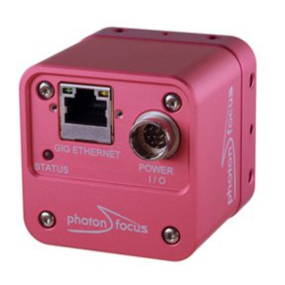
Hardware Interface 6.1 GigE Connector The GigE cameras are interfaced to external components via • an Ethernet jack (RJ45) to transmit configuration, image data and trigger. • a 12 pin subminiature connector for the power supply, Hirose HR10A-10P-12S (female) . The connectors are located on the back of the camera. -
Page 62: Status Indicator (Gige Cameras)
6 Hardware Interface A suitable power supply can be ordered from your Photonfocus dealership. For further details including the pinout please refer to Appendix A. 6.3 Status Indicator (GigE cameras) A dual-color LED on the back of the camera gives information about the current status of the GigE CMOS cameras. - Page 63 6.4 Power and Ground Connection for GigE G2 Cameras C a m e r a I n t e r n a l P o w e r S u p p l y 2 o w e r S u p p l y P O W E R D C / D C V C C _ 1...
-
Page 64: Trigger And Strobe Signals For Gige Cameras
6 Hardware Interface 6.5 Trigger and Strobe Signals for GigE Cameras 6.5.1 Overview The 12-pol. Hirose power connector contains two external trigger inputs, two strobe outputs and two differential inputs (G2 models: RS-422, H2 models: HTL). All inputs and outputs are connected to the Programmable Logic Controller (PLC) (see also Section 6.6) that offers powerful operations. - Page 65 6.5 Trigger and Strobe Signals for GigE Cameras C a m e r a I S O L A T O R R S 4 2 2 I S O _ I N C 0 _ P I S O _ I N C 0 _ N - 1 0 V t o + 1 3 V e x t e n d e d...
- Page 66 6 Hardware Interface C a m e r a I S O L A T O R H T L : i n p u t r a n g e : 1 0 V t o 3 0 V I S O _ I N C 0 _ P I S O _ I N C 0 _ N I S O _ I N C 1 _ P...
-
Page 67: Single-Ended Inputs
6.5 Trigger and Strobe Signals for GigE Cameras 6.5.2 Single-ended Inputs ISO_IN0 and ISO_IN1 are single-ended isolated inputs. The input circuit of both inputs is identical (see Fig. 6.3). Fig. 6.5 shows a direct connection to the ISO_IN inputs. In the camera default settings the PLC is configured to connect the ISO_IN0 to the PLC_Q4 camera trigger input. -
Page 68: Single-Ended Outputs
6 Hardware Interface 6.5.3 Single-ended Outputs ISO_OUT0 and ISO_OUT1 are single-ended isolated outputs. ISO_OUT0 and ISO_OUT1 have different output circuits: ISO_OUT1 doesn’t have a pullup resistor and can be used as additional Strobe out (by adding Pull up) or as controllable switch. Maximal ratings that must not be exceeded: voltage: 30 V, current: 0.5 A, power: 0.5 W. - Page 69 6.5 Trigger and Strobe Signals for GigE Cameras Fig. 6.9 shows the connection from ISO_OUT1 to a LED. 1 2 p o l . H i r o s e C a m e r a C o n n e c t o r ;...
-
Page 70: Differential Rs-422 Inputs (G2 Models)
6 Hardware Interface 6.5.4 Differential RS-422 Inputs (G2 models) ISO_INC0 and ISO_INC1 are isolated differential RS-422 inputs (see also Fig. 6.3). They are connected to a Maxim MAX3098 RS-422 receiver device. Please consult the data sheet of the MAX3098 for connection details. Don’t connect single-ended signals to the differential inputs ISO_INC0 and ISO_INC1 (see also Fig. -
Page 71: I/O Wiring
6.5 Trigger and Strobe Signals for GigE Cameras 6.5.6 I/O Wiring The Photonfocus cameras include electrically isolated inputs and outputs. Take great care when wiring trigger and strobe signals to the camera, specially over big distances (a few meters) and in noisy environments. - Page 72 6 Hardware Interface Common Grounds with Star Wiring Ground loops can be avoided using "star wiring", i.e. the wiring of power and ground connections originate from one "star point" which is typically a power supply. Fig. 6.14 shows a schematic of the star-wiring concept. Fig.
- Page 73 6.5 Trigger and Strobe Signals for GigE Cameras Fig. 6.16 shows an example of how to connect a flash light and a trigger source to the camera using star-wiring. The trigger in this example is generated from a light barrier. Note how the power and ground cables are connected to the same power supply.
- Page 74 6 Hardware Interface An example of improper wiring that causes a ground loop is shown in Fig. 6.17. C o n n e c t i n g C A M _ G N D a n d G r o u n d l o o p I S O _ G N D t h e w r o n g w a y 1 s o l a t o r I S O _ I N...
-
Page 75: Plc Connections
6.6 PLC connections 6.6 PLC connections The PLC (Programmable Logic Controller) is a powerful device where some camera inputs and outputs can be manipulated and software interrupts can be generated. Sample settings and an introduction to PLC are shown in Section 7.7. PLC is described in detail in the document [PLC]. Name Direction Description... - Page 76 6 Hardware Interface MAN066 12/2018 V1.1 76 of 103...
-
Page 77: Software
Software 7.1 Software for Photonfocus GigE Cameras The following packages for Photonfocus GigE (G2 / H2) cameras are available on the Photonfocus website (www.photonfocus.com): eBUS SDK Contains the Pleora SDK and the Pleora GigE filter drivers. Many examples of the SDK are included. -
Page 78: Pf_Gevplayer Main Window
7 Software 7.2.1 PF_GEVPlayer main window After connecting the camera (see Chapter 3), the main window displays the following controls (see Fig. 7.1): Disconnect Disconnect the camera Mode Acquisition mode Play Start acquisition Stop Stop acquisition Acquisition Control Mode Continuous, Single Frame or Multi Frame modes. The number of frames that are acquired in Multi Frame mode can be set in the GEV Device Control with AcquisitionFrameCount in the AcquisitionControl category. - Page 79 7.2 PF_GEVPlayer To have a quick overview of the available categories, all categories should be collapsed. The categories of interest can then be expanded again. If the name of the property is known, then the alphabetical view is convenient. If this is the first time that you use a Photonfocus GigE camera, then the visibility should be left to Beginner.
-
Page 80: Display Area
7 Software 7.2.3 Display Area The images are displayed in the main window in the display area. A zoom menu is available when right clicking in the display area. Another way to zoom is to press the Ctrl button while using the mouse wheel. -
Page 81: Get Feature List Of Camera
7.3 Pleora SDK 7.2.6 Get feature list of camera A list of all features of the Photonfocus GigE cameras in HTML format can be found in the GenICam_Feature_Lists sub-directory (in Start -> All Programs -> Photonfocus -> GigE_Tools). Alternatively, the feature list of the connected camera can be retrieved with the PF_GEVPlayer (Tools ->... -
Page 82: Persistent Ip Address
7 Software The calibration values of the FPN calibration are not stored with UserSetSave (or CameraHeadStoreDefaults). Use the command Correction_SaveToFlash for this (see Correction_SaveToFlash). 7.6 Persistent IP address It is possible to set a persistent IP address: Set GevPersistentIPAddress (in category TransportLayerControl) to the desired IP address. Set GevPersistentSubnetMask (in category TransportLayerControl) to the sub net mask. -
Page 83: Plc
7.7 PLC 7.7 PLC 7.7.1 Introduction The Programmable Logic Controller (PLC) is a powerful tool to generate triggers and software interrupts. A functional diagram of the PLC tool is shown in Fig. 7.4. The PLC tool is described in detail with many examples in the [PLC] manual which is included in the PFInstaller. The AB Trigger feature is not available on all camera revisions, see Appendix B for a list of available features. -
Page 84: Plc Settings For Iso_In0 To Plc_Q4 Camera Trigger
7 Software Identify the PLC notation of the desired input. A table of the PLC mapping is given in Section 6.6. In our example, ISO_IN0 maps to A0 or Line0. Select a Signal Routing Block (SRB) that has a connection to the desired PLC input and connect it to the PLC input. -
Page 85: Plc Settings For A/B Trigger From Differential Inputs
7.7 PLC 7.7.3 PLC Settings for A/B Trigger from differential inputs This settings connects the ISO_INC differential inputs to the A/B camera inputs. ISO_INC0 is mapped to the A signal and ISO_INC1 to the B signal, see Table 7.2 (the visibility in the PF_GEVPlayer must be set to Guru for this purpose). -
Page 86: Plc Settings For A/B Trigger From Single-Ended Inputs
7 Software 7.7.4 PLC Settings for A/B Trigger from single-ended inputs This configuration maps the single-ended inputs to the A/B camera inputs: ISO_IN0 is mapped to the A signal and ISO_IN1 to the B signal see Table 7.3 (the visibility in the PF_GEVPlayer must be set to Guru for this purpose). -
Page 87: Miscellaneous Properties
7.8 Miscellaneous Properties 7.8 Miscellaneous Properties 7.8.1 PixelFormat The property PixelFormat (in category ImageFormatControl) sets the pixel format. For 10 bits and 12 bits there is a selection of plain or packed format. The plain format uses more bandwidth than the packed format, but is easier to process in the software. Table 7.4 shows the number of bits per pixel to are required for a pixel format. - Page 88 7 Software MAN066 12/2018 V1.1 88 of 103...
-
Page 89: Mechanical Considerations
Mechanical Considerations 8.1 Mechanical Interface During storage and transport, the camera should be protected against vibration, shock, moisture and dust. The original packaging protects the camera adequately from vibration and shock during storage and transport. Please either retain this packaging for possible later use or dispose of it according to local regulations. -
Page 90: Adjusting The Back Focus
8 Mechanical Considerations 8.2 Adjusting the Back Focus The back focus of your Photonfocus camera is correctly adjusted in the production of the camera. This section describes the procedure to adjust the back focus if you require that because e.g. you are using a special lens. -
Page 91: Standards Compliance
Standards Compliance 9.1 Directives and General Standards The products described in this manual in the form as delivered are in conformity with the provisions of the following European Directives: • 2014/30/EU Electromagnetic compatibility (EMC) • 2014/35/EU Low Voltage (LVD) • 2011/65/EU Restriction of hazardous substances (RoHS) Conformity to the Directives is assured through the application of the following standards: Emission:... -
Page 92: For Customers In Canada
9 Standards Compliance You are cautioned that any changes or modifications not expressly approved in this manual could void your authority to operate this equipment. The shielded interface cable recommended in this manual must be used with this equipment in order to comply with the limits for a computing device pursuant to Subpart B of Part 15 of FCC Rules. -
Page 93: Warranty
Warranty The manufacturer alone reserves the right to recognize warranty claims. 10.1 Warranty Terms The manufacturer warrants to distributor and end customer that for a period of two years from the date of the shipment from manufacturer or distributor to end customer (the "Warranty Period") that: •... - Page 94 10 Warranty Avoid cleaning the sensor with improper methods. Follow the instructions in the corresponding chapter of this manual. Transport and store the camera in its original packaging only and protect the sensor and the lens mount with a camera body cap. 10.
-
Page 95: Support And Repair
Support and Repair This chapter describes the product support and repair. 11.1 Technical Support First level technical support is given from the sales department of Photonfocus or your local dealer. In case your issue could not be solved in this way Photonfocus support team takes over. The Photonfocus support team is available via email: support@photonfocus.com. - Page 96 11 Support and Repair MAN066 12/2018 V1.1 96 of 103...
-
Page 97: References
References All referenced documents can be downloaded from our website at www.photonfocus.com. AN007 Application Note "Camera Acquisition Modes", Photonfocus, March 2004 GEVQS GEVPlayer Quick Start Guide, Pleora Technologies. Included in eBUS installer. MAN051 Manual "Photonfocus GigE Quick Start Guide", Photonfocus PLC iPORT Programmable Logic Controller Reference Guide, Pleora Technologies. - Page 98 12 References MAN066 12/2018 V1.1 98 of 103...
-
Page 99: A Pinouts
Pinouts A.1 Power Supply Connector The power supply connectors are available from Hirose connectors at www.hirose-connectors.com. Fig. A.1 shows the power supply plug from the solder side. The pin assignment of the power supply plug is given in Table A.2. It is extremely important that you apply the appropriate voltages to your camera. - Page 100 A Pinouts I/O Type Name Description CAMERA_GND Camera GND, 0V CAMERA_PWR Camera Power 12V..24V ISO_OUT0 Default Strobe out, internally Pulled up to ISO_PWR with 4k7 Resistor ISO_INC0_N INC0 differential input (G2: RS-422, H2: HTL), negative polarity ISO_INC0_P INC0 differential input (G2: RS-422, H2: HTL), positive polarity ISO_PWR Power supply 5V..24V for output signals...
-
Page 101: B Camera Revisions
Camera Revisions B.1 General Remarks This chapter lists differences between the revisions of the camera models. List of terms used in this chapter: Standard Trigger Standard trigger features. Trigger Source: Free running, Software Trigger, Line1 Trigger, PLC_Q4 Trigger. Exposure Time Control: Camera-controlled, Trigger-controlled. - Page 102 B Camera Revisions MAN066 12/2018 V1.1 102 of 103...
-
Page 103: C Document Revision History
Document Revision History Revision Date Changes April 2015 First version December 2018 - Updated power supply connector description - Chapter "Warranty" modified - Chapter "Standards Compliance" added - Chapter "Support and Repair" added MAN066 12/2018 V1.1 103 of 103...
Need help?
Do you have a question about the MV1-R1280-50 Series and is the answer not in the manual?
Questions and answers