
Related Manuals for Photon Focus MV1-D1312-3D02 Series


Summary of Contents for Photon Focus MV1-D1312-3D02 Series
- Page 1 Photonfocus MV1-D1312-3D02 Camera Series CMOS camera with GigE interface MAN056 08/2018 V1.1...
- Page 2 All information provided in this manual is believed to be accurate and reliable. No responsibility is assumed by Photonfocus AG for its use. Photonfocus AG reserves the right to make changes to this information without notice. Reproduction of this manual in whole or in part, by any means, is prohibited without prior permission having been obtained from Photonfocus AG.
-
Page 3: Table Of Contents
Contents 1 Preface 1.1 IMPORTANT NOTICE! ........1.2 About Photonfocus . - Page 4 CONTENTS 4.4.3 Exposure Control ........53 4.4.4 Maximum Frame Rate .
- Page 5 CONTENTS 6.2.5 Save camera setting to a file ......104 6.2.6 Get feature list of camera ......105 6.3 Pleora SDK .
- Page 6 CONTENTS MAN056 08/2018 V1.1 6 of 129...
-
Page 7: Preface
Preface 1.1 IMPORTANT NOTICE! READ THE INSTRUCTIONS FOR USE BEFORE OPERATING THE CAMERA STORE THE INSTRUCTIONS FOR USE FOR FURTHER READING Photonfocus AG Bahnhofplatz 10 CH-8853 Lachen SZ Switzerland www.photonfocus.com info@photonfocus.com +41 – 55 451 00 00 MAN056 08/2018 V1.1 7 of 129... -
Page 8: About Photonfocus
1 Preface 1.2 About Photonfocus The Swiss company Photonfocus is one of the leading specialists in the development of CMOS image sensors and corresponding industrial cameras for machine vision. Photonfocus is dedicated to making the latest generation of CMOS technology commercially available. -
Page 9: Legend
1.6 Legend 1.6 Legend In this documentation the reader’s attention is drawn to the following icons: Important note, additional information Important instructions General warning, possible component damage hazard Warning, electric shock hazard Warning, fire hazard MAN056 08/2018 V1.1 9 of 129... - Page 10 1 Preface MAN056 08/2018 V1.1 10 of 129...
-
Page 11: How To Get Started (3D Gige G2)
How to get started (3D GigE G2) 2.1 Introduction This guide shows you: • How to install the required hardware (see Section 2.2) • How to install the required software (see Section 2.3) and configure the Network Adapter Card (see Section 2.4 and Section 2.5) •... - Page 12 2 How to get started (3D GigE G2) Do not bend GigE cables too much. Excess stress on the cable results in transmis- sion errors. In robots applications, the stress that is applied to the GigE cable is especially high due to the fast movement of the robot arm. For such applications, special drag chain capable cables are available.
-
Page 13: Software Installation
2.3 Software Installation 2.3 Software Installation This section describes the installation of the required software to accomplish the tasks described in this chapter. Install the latest drivers for your GigE network interface card. Download the latest eBUS SDK installation file from the Photonfocus server. You can find the latest version of the eBUS SDK on the support (Software Down- load) page at www.photonfocus.com. - Page 14 2 How to get started (3D GigE G2) Figure 2.3: PFInstaller components choice MAN056 08/2018 V1.1 14 of 129...
-
Page 15: Network Adapter Configuration
2.4 Network Adapter Configuration 2.4 Network Adapter Configuration This section describes recommended network adapter card (NIC) settings that enhance the performance for GigEVision. Additional tool-specific settings are described in the tool chapter. Open the Network Connections window (Control Panel -> Network and Internet Connections ->... - Page 16 2 How to get started (3D GigE G2) By default, Photonfocus GigE Vision cameras are configured to obtain an IP address automatically. For this quick start guide it is recommended to configure the network adapter to obtain an IP address automatically. To do this, select Internet Protocol (TCP/IP) (see Fig.
- Page 17 2.4 Network Adapter Configuration Open again the Local Area Connection Properties window (see Fig. 2.4) and click on the Configure button. In the window that appears click on the Advanced tab and click on Jumbo Frames in the Settings list (see Fig. 2.6). The highest number gives the best performance. Some tools however don’t support the value 16128.
- Page 18 2 How to get started (3D GigE G2) No firewall should be active on the network adapter where the Photonfocus GigE camera is connected. If the Windows Firewall is used then it can be switched off like this: Open the Windows Firewall configuration (Start -> Control Panel -> Network and Internet Connections ->...
-
Page 19: Network Adapter Configuration For Pleora Ebus Sdk
2.5 Network Adapter Configuration for Pleora eBUS SDK 2.5 Network Adapter Configuration for Pleora eBUS SDK Open the Network Connections window (Control Panel -> Network and Internet Connections -> Network Connections), right click on the name of the network adapter where the Photonfocus camera is connected and select Properties from the drop down menu that appears. -
Page 20: Getting Started
2 How to get started (3D GigE G2) 2.6 Getting started This section describes how to acquire images from the camera and how to modify camera settings. Open the PF_GEVPlayer software (Start -> All Programs -> Photonfocus -> GigE_Tools -> PF_GEVPlayer) which is a GUI to set camera parameters and to see the grabbed images (see Fig. - Page 21 2.6 Getting started Click on the Select / Connect button in the PF_GEVPlayer . A window with all detected devices appears (see Fig. 2.10). If your camera is not listed then select the box Show unreachable GigE Vision Devices. Figure 2.10: GEV Device Selection Procedure displaying the selected camera Select camera model to configure and click on Set IP Address..
- Page 22 2 How to get started (3D GigE G2) Select a valid IP address for selected camera (see Fig. 2.12). There should be no exclamation mark on the right side of the IP address. Click on Ok in the Set IP Address dialog.
- Page 23 2.6 Getting started If no images can be grabbed, close the PF_GEVPlayer and adjust the Jumbo Frame parameter (see Section 2.3) to a lower value and try again. Figure 2.14: PF_GEVPlayer displaying live image stream Check the status LED on the rear of the camera. The status LED light is green when an image is being acquired, and it is red when serial communication is active.
- Page 24 2 How to get started (3D GigE G2) To modify the exposure time scroll down to the AcquisitionControl control category (bold title) and modify the value of the ExposureTime property. MAN056 08/2018 V1.1 24 of 129...
-
Page 25: Product Specification 3.1 Introduction
Product Specification 3.1 Introduction The MV1-D1312-3D02-160-G2-12 is a 1.3 megapixel Gigabit Ethernet CMOS camera from Photonfocus optimized for high speed laser triangulation applications with up to 3250 profiles/s (1312 x16) or 5500 profiles/s (544 x 16). The camera contains the Photonfocus A1312 image sensor that has a high dynamic range which is beneficial for laser triangulation, specially on reflective surfaces. - Page 26 3 Product Specification L a s e r C a m e r a + o n v e y o r b e l t w i t h o b j e c t s Figure 3.1: Triangulation principle with objects moved on a conveyor belt Generic Int erface for Cameras Figure 3.2: Camera MV1-D1312-3D02-160-G2-12 is GenICam compliant Figure 3.3: Camera MV1-D1312-3D02-160-G2-12 is GigE Vision compliant...
-
Page 27: Feature Overview
3.2 Feature Overview 3.2 Feature Overview The general specification and features of the camera are listed in the following sections. The detailed description of the camera features is given in Chapter 4. MV1-D1312-3D02-160-G2 Interface Gigabit Ethernet Camera Control GigE Vision Suite / PF 3D Suite Trigger Modes External isolated trigger inputs / Software Trigger / PLC Trigger / AB Trigger Features... -
Page 28: Technical Specification
3 Product Specification 3.3 Technical Specification MV1-D1312-3D02-160-G2 Sensor Photonfocus A1312 Technology CMOS active pixel Scanning system progressive scan Optical format / diagonal 1” (13.6 mm diagonal) @ maximum resolution 2/3” (11.6 mm diagonal) @ 1024 x 1024 resolution Resolution 1312 x 1024 pixels Pixel size 8 m x 8 m Active optical area... - Page 29 3.3 Technical Specification MV1-D1312-3D02-160-G2 Operating temperature / moisture 0°C ... 50°C / 20 ... 80 % Storage temperature / moisture -25°C ... 60°C / 20 ... 95 % Camera power supply +12 V DC (- 10 %) ... +24 V DC (+ 10 %) Trigger signal input range +5 ..
- Page 30 3 Product Specification MAN056 08/2018 V1.1 30 of 129...
-
Page 31: Functionality
Functionality 4.1 Introduction This chapter serves as an overview of the camera configuration modes and explains camera features. The goal is to describe what can be done with the camera. The setup of the MV1-D1312-3D02-160-G2 camera is explained in later chapters. 4.2 3D Features 4.2.1 Overview The MV1-D1312-3D02 camera contains a very accurate laser line detector for laser triangulation... - Page 32 4 Functionality Triangulation Setup 1 In this setup the camera looks with the viewing angle on the laser line projected from the top. A larger angle leads to a higher resolution. With larger angles the range of height is reduced. Small angles have the benefit of little occlusions. Line Laser Camera Figure 4.1: Triangulation setup 1...
- Page 33 4.2 3D Features Triangulation Setup 3 In this setup the laser line generator and the camera are placed in a more reflecting configuration. This gives more signal and could be used for dark or matte surfaces. In case of reflecting surfaces there is only a little amount of scattering which can be used as signal for triangulation.
-
Page 34: Laser Line Detection
4 Functionality 4.2.3 Laser Line Detection The laser line detector takes a threshold value as its input. The threshold has two purposes: • All pixels with grey value below the threshold value will be ignored. This filters out the image background. •... -
Page 35: Interpolation Technique
4.2 3D Features Figure 4.6: WidthMap of a wood plank 4.2.4 Interpolation Technique Structured light based systems crucially rely on an accurate determination of the peak position of the Gaussian shaped laser line. The Peak Detector algorithm in the MV1-D1312-3D02 camera applies nonlinear interpolation techniques, where 64 data points are calculated between two pixels within the Gaussian shaped laser line. - Page 36 4 Functionality ( r o t a t e d b y 9 0 ° ) I n t e r p o l a t e d r e s o l u t i o n M a x i m u m v a l u e i n t e r p o l a t i o n G a u s s i a n s h a p e d c r o s s...
-
Page 37: Modes
4.2 3D Features Fig. 4.8 shows a comparison of the peak detector algorithm of MV1-D1312-3D02 camera against the Center Of Gravity (COG) algorithm that is used in most triangulation systems. It can clearly be observed that the Peak Detector algorithm gives more accurate results. Figure 4.8: Comparison of peak detector algorithm against COG algorithm 4.2.5 3D modes The camera has three modes that determine which data is transmitted to the user:... -
Page 38: Data Format
4 Functionality 4.2.6 3D data format For the laser peak detector there are 4 additional lines that contain the 3D data. Every pixel contains 8 bits of 3D data which are always placed in the 8 LSB. A table with the bit assignment of the 3D data is shown in Fig. -
Page 39: Frame Combine
4.2 3D Features Resulting height in 3Donly mode is therefore 4*f. 9 i d t h 3 D d a t a f o r i m a g e i 3 D d a t a f o r i m a g e i + 1 3 D d a t a f o r i m a g e i + 2 3 D d a t a f o r i m a g e i + 3 Figure 4.11: Transmitted image in 3Donly mode with FrameCombine=4... -
Page 40: Peak Filter
4 Functionality 4.2.10 Peak Filter Peaks that are detected by the PeakDetector algorithm can be filtered by applying the parameters described in this section. A filtered peak appears as all 3D data set to 0, which is the same as if no peak occured. Filtering peaks might increase the robustness of the 3D application by filtering peaks that were caused by unwanted effects, such as reflections of the laser beam. - Page 41 4.2 3D Features An illustration of the PeakFilter_Width parameters is shown in Fig. 4.13. The red line denotes a situation where the laser peak is filtered because the width is too big or too small. f i l t e r e d : w i d t h t o o b i g f i l t e r e d : w i d t h t o o s m a l l 2 * T h r e s h o l d...
-
Page 42: Reduction Of Image Size
4 Functionality 4.3 Reduction of Image Size With Photonfocus cameras there are several possibilities to focus on the interesting parts of an image, thus reducing the data rate and increasing the frame rate. The most commonly used feature is Region of Interest (ROI). 4.3.1 Region of Interest (ROI) Some applications do not need full image resolution (1312 x 1024 pixels). - Page 43 4.3 Reduction of Image Size ROI Dimension Frame rate 3Donly mode Frame rate 2D&3D mode 1312 x 1024 (full resolution) 113 fps 57 fps 1280 x 1024 (SXGA) 116 fps 59 fps 1280 x 768 (WXGA) 154 fps 78 fps 800 x 600 (SVGA) 305 fps 157 fps...
-
Page 44: Roi Configuration
4 Functionality 4.3.2 ROI configuration In the MV1-D1312-3D02-160 camera the following restrictions have to be respected for the ROI configuration: • The minimum width (w) of the ROI is 544 pixel. • The region of interest must overlap a minimum number of pixels centered to the left and to the right of the vertical middle line of the sensor (ovl). - Page 45 4.3 Reduction of Image Size Width MV1-D1312-3D02-160-G2 < 544 not available 352 ... 384 320 ... 352 288 ... 384 256 ... 384 224 ... 384 192 ... 384 160 ... 384 128 ... 384 96 ... 384 64 ... 384 32 ...
-
Page 46: Decimation
4 Functionality Exposure time 3Donly mode 2D&3D mode 10 s 429 / 429 fps 227 / 227 fps 100 s 413 / 425 fps 222 / 226 fps 500 s 354 / 424 fps 204 / 225 fps 1 ms 301 / 423 fps 185 / 225 fps 2 ms... - Page 47 4.3 Reduction of Image Size Fig. 4.17 shows decimation on a ROI. The row specified by the Window.Y setting is first read out and then every n row until the end of the ROI. 0 , 0 ) R O I ( 1 3 1 1 , 1 0 8 1 ) Figure 4.17: Decimation and ROI The image in Fig.
-
Page 48: Image Acquisition
4 Functionality 4.4 Image Acquisition 4.4.1 Readout Modes The MV1-D1312 CMOS cameras provide two different readout modes: Sequential readout Frame time is the sum of exposure time and readout time. Exposure time of the next image can only start if the readout time of the current image is finished. Simultaneous readout (interleave) The frame time is determined by the maximum of the exposure time or of the readout time, which ever of both is the longer one. - Page 49 4.4 Image Acquisition In simultaneous readout mode image output faces minor limitations. The overall linear sensor reponse is partially restricted in the lower grey scale region. When changing readout mode from sequential to simultaneous readout mode or vice versa, new settings of the BlackLevelOffset and of the image correction are required.
-
Page 50: Readout Timing
4 Functionality e x p o s u r e n - 1 e x p o s u r e n + 1 A x p o s u r e n i d l e i d l e r e a d o u t n - 1 r e a d o u t n f r a m e t i m e... - Page 51 4.4 Image Acquisition 2 C L K F r a m e T i m e S H U T T E R E x p o s u r e T i m e F V A L C P R E L i n e p a u s e L i n e p a u s e L i n e p a u s e...
- Page 52 4 Functionality 2 C L K F r a m e T i m e S H U T T E R E x p o s u r e E x p o s u r e T i m e T i m e F V A L C P R E...
-
Page 53: Exposure Control
4.4 Image Acquisition Frame time Frame time is the inverse of the frame rate. Exposure time Period during which the pixels are integrating the incoming light. Pixel clock on internal camera interface. PCLK SHUTTER Internal signal, shown only for clarity. Is ’high’ during the exposure time. -
Page 54: Pixel Response
4 Functionality 4.5 Pixel Response 4.5.1 Linear Response The camera offers a linear response between input light signal and output grey level. This can ® be modified by the use of LinLog as described in the following sections. In addition, a linear digital gain may be applied, as follows. - Page 55 4.5 Pixel Response / r e y V a l u e S a t u r a t i o n 1 0 0 % W e a k c o m p r e s s i o n L i n e a r R e s p o n s e R e s u l t i n g L i n l o g...
- Page 56 4 Functionality Typical LinLog1 Response Curve − Varying Parameter Value1 Time1=1000, Time2=1000, Value2=Value1 V1 = 15 V1 = 16 V1 = 17 V1 = 18 V1 = 19 Illumination Intensity Figure 4.30: Response curve for different LinLog settings in LinLog1 mode L i n L o g e x p V a l u e 1...
- Page 57 4.5 Pixel Response Typical LinLog2 Response Curve − Varying Parameter Time1 Time2=1000, Value1=19, Value2=14 T1 = 840 T1 = 920 T1 = 960 T1 = 980 T1 = 999 Illumination Intensity Figure 4.32: Response curve for different LinLog settings in LinLog2 mode Typical LinLog2 Response Curve −...
- Page 58 4 Functionality L i n L o g e x p V a l u e 1 V a l u e 2 T i m e 1 V a l u e 3 = C o n s t a n t = 0 6 i m e 2 T i m e 1 T i m e 2...
-
Page 59: Trigger And Strobe
4.6 Trigger and Strobe 4.6 Trigger and Strobe 4.6.1 Trigger Source The trigger signal can be configured to be active high or active low by the TriggerActivation (category AcquisitionControl) property. One of the following trigger sources can be used: Free running The trigger is generated internally by the camera. Exposure starts immediately after the camera is ready and the maximal possible frame rate is attained, if AcquisitionFrameRateEnable is disabled. - Page 60 4 Functionality Figure 4.36: Trigger source Figure 4.37: Trigger Inputs - Multiple GigE solution MAN056 08/2018 V1.1 60 of 129...
-
Page 61: Acquisition Mode
4.6 Trigger and Strobe 4.6.2 Acquisition Mode The available acquisition modes are shown in Table 4.8. The ContinuousRecording and ContinousReadout modes can be used if more than one camera is connected to the same network and need to shoot images si- multaneously. -
Page 62: Exposure Time Control
4 Functionality 4.6.3 Exposure Time Control Depending on the trigger mode, the exposure time can be determined either by the camera or by the trigger signal itself: Camera-controlled Exposure time In this trigger mode the exposure time is defined by the camera. - Page 63 4.6 Trigger and Strobe camera environment to allow robust integration of the camera into the vision system. In the signal isolator the trigger signal is delayed by time t . This signal is clocked into the d iso input FPGA which leads to a jitter of t .
-
Page 64: Trigger Delay
4 Functionality The timing of the rising edge of the trigger pulse until to the start of exposure and strobe is equal to the timing of the camera controlled exposure time (see Section 4.6.3). In this mode however the end of the exposure is controlled by the falling edge of the trigger Pulsewidth: The falling edge of the trigger pulse is delayed by the time t which is results from the d iso input... - Page 65 4.6 Trigger and Strobe A x t e r n a l t r i g g e r p u l s e i n p u t t r i g g e r a f t e r i s o l a t o r d - i s o - i n p u t t r i g g e r p u l s e i n t e r n a l c a m e r a c o n t r o l j i t t e r...
- Page 66 4 Functionality MV1-D1312-3D02-160-G2 MV1-D1312-3D02-160-G2 Timing Parameter Minimum Maximum 1.5 s d iso input 65 ns 185 ns d RS422 input 25 ns jitter 0.42 s trigger delay 0.42 s burst trigger delay depends on camera settings 0.42 s burst period time (non burst mode) 100 ns 100 ns...
-
Page 67: Software Trigger
4.6 Trigger and Strobe 4.6.6 Software Trigger The software trigger enables to emulate an external trigger pulse by the camera software through the serial data interface. It works with both burst mode enabled and disabled. As soon as it is performed via the camera software, it will start the image acquisition(s), depending on the usage of the burst mode and the burst configuration. - Page 68 4 Functionality Double Two triggers are generated on every A/B sequence (see Fig. 4.42). Quad Four triggers are generated on every A/B sequence (see Fig. 4.43). There is a bug in the single A/B trigger mode in some camera revisions (see Ap- pendix ??).
- Page 69 4.6 Trigger and Strobe A/B Trigger Debounce A debouncing logic can be enabled by setting ABTriggerDeBounce=True. It is implemented with a watermark value of the EncoderCounter (see Fig. 4.44). Suppose ABTriggerDirection=fwd, then the watermark value is increased with the increments of the EncoderCounter. If EncoderCounter decreases, e.g.
- Page 70 4 Functionality A/B Trigger Divider if ABTriggerDivider>1 then not all internally generated triggers are applied to the camera logic. E.g. If ABTriggerDivider=2, then every second trigger is applied to the camera (see Fig. 4.46). G r a y C o u n t e r E n c o d e r C o u n t e r I n t e r n a l T r i g g e r F w d A p p l i e d T r i g g e r F w d...
-
Page 71: Strobe Output
4.6 Trigger and Strobe By default the Encoder Position is only generated when TriggerMode=On and TriggerSource=ABTrigger. When the property ABTriggerCountAlways=True, then the Encoder Position is generated regardless of the trigger mode. 4.6.8 Strobe Output The strobe output is an isolated output located on the power supply connector that can be used to trigger a strobe. -
Page 72: Data Path Overview
4 Functionality 4.7 Data Path Overview The data path is the path of the image from the output of the image sensor to the output of the camera. The sequence of blocks is shown in figure Fig. 4.49. 1 m a g e S e n s o r F P N C o r r e c t i o n D i g i t a l O f f s e t... -
Page 73: Offset Correction (Fpn, Hot Pixels)
4.8 Image Correction Since the correction is performed in hardware, there is no performance limita- tion of the cameras for high frame rates. The offset correction subtracts a configurable positive or negative value from the live image and thus reduces the fixed pattern noise of the CMOS sensor. In addition, hot pixels can be removed by interpolation. - Page 74 4 Functionality " a v e r a g e o f b l a c k r e f e r e n c e p i c t u r e > l a c k r e f e r e n c e o f f s e t c o r r e c t i o n i m a g e m a t r i x...
-
Page 75: Gain Correction
4.8 Image Correction Hot pixel correction Every pixel that exceeds a certain threshold in the black reference image is marked as a hot pixel. If the hot pixel correction is switched on, the camera replaces the value of a hot pixel by an average of its neighbour pixels (see Fig. -
Page 76: Corrected Image
4 Functionality 0 . 8 0 . 9 a v e r a g e o f g r a y 1 . 2 0 . 8 1 . 3 1 . 2 r e f e r e n c e 0 . - Page 77 4.8 Image Correction Histogram of the uncorrected grey reference image grey reference image ok grey reference image too bright 2400 2600 2800 3000 3200 3400 3600 3800 4000 4200 Grey level, 12 Bit [DN] Figure 4.54: Proper grey reference image for gain correction 0 .
-
Page 78: Digital Gain And Offset
4 Functionality 4.9 Digital Gain and Offset There are two different gain settings on the camera: Gain (Digital Fine Gain) Digital fine gain accepts fractional values from 0.01 up to 15.99. It is implemented as a multiplication operation. Digital Gain Digital Gain is a coarse gain with the settings x1, x2, x4 and x8. It is implemented as a binary shift of the image data where ’0’... - Page 79 4.10 Crosshairs Figure 4.56: Crosshairs Example with different grey values MAN056 08/2018 V1.1 79 of 129...
-
Page 80: Image Information And Status Information
4 Functionality 4.11 Image Information and Status Information There are camera properties available that give information about the acquired images, such as an image counter and the number of missed trigger signals. These properties can be queried by software. 4.11.1 Counters Image counter The image counter provides a sequential number of every image that is output. -
Page 81: Status Information
4.12 3D Test image 4.11.2 Status Information Status information is inserted in the 4 LSB in the last 3D data row (see bits labeled STAT in Fig. 4.9). LSB are transmitted first (see Table 4.11). The status information is divided in fields of 32 bits each, where every information field corresponds to one information parameter (see Table 4.12). -
Page 82: Ramp
4 Functionality Figure 4.57: 3D test image 4.13.1 Ramp Depending on the configured grey level resolution, the ramp test image outputs a constant pattern with increasing grey level from the left to the right side (see Fig. 4.58). Figure 4.58: Ramp test images: 8 bit output (left), 10 bit output (middle),12 (right) 4.13.2 LFSR The LFSR (linear feedback shift register) test image outputs a constant pattern with a pseudo-random grey level sequence containing every possible grey level that is repeated for... -
Page 83: Troubleshooting Using The Lfsr
4.13 2D Test Images Figure 4.59: LFSR (linear feedback shift register) test image 4.13.3 Troubleshooting using the LFSR To control the quality of your complete imaging system enable the LFSR mode, set the camera window to 1024 x 1024 pixels (x=0 and y=0) and check the histogram. If your frame grabber application does not provide a real-time histogram, store the image and use a graphic software tool to display the histogram. - Page 84 4 Functionality Figure 4.60: LFSR test pattern received and typical histogram for error-free data transmission Figure 4.61: LFSR test pattern received and histogram containing transmission errors In robots applications, the stress that is applied to the camera cable is especially high due to the fast movement of the robot arm.
-
Page 85: Hardware Interface
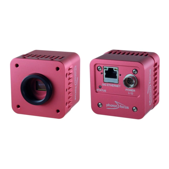
Hardware Interface 5.1 GigE Connector The GigE cameras are interfaced to external components via • an Ethernet jack (RJ45) to transmit configuration, image data and trigger. • a 12 pin subminiature connector for the power supply, Hirose HR10A-10P-12S (female) . The connectors are located on the back of the camera. -
Page 86: Status Indicator (Gige Cameras)
5 Hardware Interface 5.3 Status Indicator (GigE cameras) A dual-color LED on the back of the camera gives information about the current status of the GigE CMOS cameras. LED Green Green when an image is output. At slow frame rates, the LED blinks with the FVAL signal. - Page 87 5.4 Power and Ground Connection for GigE G2 Cameras C a m e r a I n t e r n a l P o w e r S u p p l y 2 o w e r S u p p l y P O W E R D C / D C V C C _ 1...
-
Page 88: Trigger And Strobe Signals For Gige Cameras
5 Hardware Interface 5.5 Trigger and Strobe Signals for GigE Cameras 5.5.1 Overview The 12-pol. Hirose power connector contains two external trigger inputs, two strobe outputs and two differential inputs (G2 models: RS-422, H2 models: HTL). All inputs and outputs are connected to the Programmable Logic Controller (PLC) (see also Section 5.6) that offers powerful operations. - Page 89 5.5 Trigger and Strobe Signals for GigE Cameras C a m e r a I S O L A T O R R S 4 2 2 I S O _ I N C 0 _ P I S O _ I N C 0 _ N - 1 0 V t o + 1 3 V e x t e n d e d...
- Page 90 5 Hardware Interface C a m e r a I S O L A T O R H T L : i n p u t r a n g e : 1 0 V t o 3 0 V I S O _ I N C 0 _ P I S O _ I N C 0 _ N I S O _ I N C 1 _ P...
-
Page 91: Single-Ended Inputs
5.5 Trigger and Strobe Signals for GigE Cameras 5.5.2 Single-ended Inputs ISO_IN0 and ISO_IN1 are single-ended isolated inputs. The input circuit of both inputs is identical (see Fig. 5.3). Fig. 5.5 shows a direct connection to the ISO_IN inputs. In the camera default settings the PLC is configured to connect the ISO_IN0 to the PLC_Q4 camera trigger input. -
Page 92: Single-Ended Outputs
5 Hardware Interface 5.5.3 Single-ended Outputs ISO_OUT0 and ISO_OUT1 are single-ended isolated outputs. ISO_OUT0 and ISO_OUT1 have different output circuits: ISO_OUT1 doesn’t have a pullup resistor and can be used as additional Strobe out (by adding Pull up) or as controllable switch. Maximal ratings that must not be exceeded: voltage: 30 V, current: 0.5 A, power: 0.5 W. - Page 93 5.5 Trigger and Strobe Signals for GigE Cameras Fig. 5.9 shows the connection from ISO_OUT1 to a LED. 1 2 p o l . H i r o s e C a m e r a C o n n e c t o r ;...
-
Page 94: Differential Rs-422 Inputs (G2 Models)
5 Hardware Interface 5.5.4 Differential RS-422 Inputs (G2 models) ISO_INC0 and ISO_INC1 are isolated differential RS-422 inputs (see also Fig. 5.3). They are connected to a Maxim MAX3098 RS-422 receiver device. Please consult the data sheet of the MAX3098 for connection details. Don’t connect single-ended signals to the differential inputs ISO_INC0 and ISO_INC1 (see also Fig. -
Page 95: I/O Wiring
5.5 Trigger and Strobe Signals for GigE Cameras 5.5.6 I/O Wiring The Photonfocus cameras include electrically isolated inputs and outputs. Take great care when wiring trigger and strobe signals to the camera, specially over big distances (a few meters) and in noisy environments. - Page 96 5 Hardware Interface Common Grounds with Star Wiring Ground loops can be avoided using "star wiring", i.e. the wiring of power and ground connections originate from one "star point" which is typically a power supply. Fig. 5.14 shows a schematic of the star-wiring concept. Fig.
- Page 97 5.5 Trigger and Strobe Signals for GigE Cameras Fig. 5.16 shows an example of how to connect a flash light and a trigger source to the camera using star-wiring. The trigger in this example is generated from a light barrier. Note how the power and ground cables are connected to the same power supply.
-
Page 98: Plc Connections
5 Hardware Interface An example of improper wiring that causes a ground loop is shown in Fig. 5.17. C o n n e c t i n g C A M _ G N D a n d G r o u n d l o o p I S O _ G N D t h e w r o n g w a y 1 s o l a t o r I S O _ I N... - Page 99 5.6 PLC connections Name Direction Description A0 (Line0) Power connector -> PLC ISO_IN0 input signal A1(Line1) Power connector -> PLC ISO_IN1 input signal A2 (Line2) Power connector -> PLC ISO_INC0 input signal A3 (Line3) Power connector -> PLC ISO_INC1 input signal camera head ->...
- Page 100 5 Hardware Interface MAN056 08/2018 V1.1 100 of 129...
-
Page 101: Software
Software 6.1 Software for MV1-D1312-3D02-160-G2 The following software packages for Photonfocus MV1-D1312-3D02-160-G2 camera are available on the Photonfocus website: eBUS SDK Contains the Pleora SDK and the Pleora GigE filter drivers. Many examples of the SDK are included. PFInstaller Contains the PF_GEVPlayer, the PF 3D Suite and SDK, a property list for every GigE camera and additional documentation and examples. -
Page 102: Pf_Gevplayer Main Window
6 Software 6.2.1 PF_GEVPlayer main window After connecting the camera (see Chapter 2), the main window displays the following controls (see Fig. 6.1): Disconnect Disconnect the camera Mode Acquisition mode Play Start acquisition Stop Stop acquisition Acquisition Control Mode Continuous, Single Frame or Multi Frame modes. The number of frames that are acquired in Multi Frame mode can be set in the GEV Device Control with AcquisitionFrameCount in the AcquisitionControl category. - Page 103 6.2 PF_GEVPlayer To have a quick overview of the available categories, all categories should be collapsed. The categories of interest can then be expanded again. If the name of the property is known, then the alphabetical view is convenient. If this is the first time that you use a Photonfocus GigE camera, then the visibility should be left to Beginner.
-
Page 104: Display Area
6 Software 6.2.3 Display Area The images are displayed in the main window in the display area. A zoom menu is available when right clicking in the display area. Another way to zoom is to press the Ctrl button while using the mouse wheel. -
Page 105: Get Feature List Of Camera
6.3 Pleora SDK 6.2.6 Get feature list of camera A list of all features of the Photonfocus GigE cameras in HTML format can be found in the GenICam_Feature_Lists sub-directory (in Start -> All Programs -> Photonfocus -> GigE_Tools). Alternatively, the feature list of the connected camera can be retrieved with the PF_GEVPlayer (Tools ->... -
Page 106: Peak Detector) Settings
6 Software 6.6 3D (Peak Detector) settings This section describes how to the set the 3D properties. These properties are described in Section 4.2. Set ROI for laser line detection through the properties OffsetX, Width, OffsetY, Window_H and DecimationVertical (all in category ImageFormatControl). Set threshold value for laser peak with property PeakDetector_Threshold (in category PeakDetector) (see also note in Section 4.2.3). -
Page 107: Offset Correction (Calibrateblack)
6.8 Calibration of the FPN Correction Resolution Frame rate Data format Data rate 1312x1024 57 fps 8 bit 615 Mbit/s 1312x1024 57 fps 10 bit / 12 bit 1230 Mbit/s * 1312x1024 57 fps 10 bit packed 769 Mbit/s 1312x1024 57 fps 12 bit packed 922 Mbit/s *... -
Page 108: Gain Correction (Calibrategrey)
6 Software 6.8.2 Gain Correction (CalibrateGrey) The gain correction is based on a gray reference image, which is taken at uniform illumination to give an image with a mid gray level. Gain correction is not a trivial feature. The quality of the gray reference image is crucial for proper gain correction. -
Page 109: Persistent Ip Address
6.10 Persistent IP address The calibration values of the FPN calibration are not stored with UserSetSave (or CameraHeadStoreDefaults). Use the command Correction_SaveToFlash for this (see Correction_SaveToFlash). 6.10 Persistent IP address It is possible to set a persistent IP address: Set GevPersistentIPAddress (in category TransportLayerControl) to the desired IP address. Set GevPersistentSubnetMask (in category TransportLayerControl) to the sub net mask. -
Page 110: Plc Settings
6 Software 6.11 PLC Settings 6.11.1 Introduction The Programmable Logic Controller (PLC) is a powerful tool to generate triggers and software interrupts. A functional diagram of the PLC tool is shown in Fig. 6.4. THE PLC tool is described in detail with many examples in the [PLC] manual which is included in the PFInstaller. S t r o b e I S O _ O U T 0 O f f... -
Page 111: Plc Settings For Iso_In0 To Plc_Q4 Camera Trigger
6.11 PLC Settings to Line0. To connect the SRB to input, set PLC_I<x> to the input. In the example, set PLC_I0 to Line0. Identify the PLC notation of the desired output. A table of the PLC mapping is given in Section 5.6. -
Page 112: Plc Settings For A/B Trigger From Differential Inputs
6 Software 6.11.3 PLC Settings for A/B Trigger from differential inputs This settings connects the ISO_INC differential inputs to the A/B camera inputs. ISO_INC0 is mapped to the A signal and ISO_INC1 to the B signal, see Table 6.3 (the visibility in the PF_GEVPlayer must be set to Guru for this purpose). -
Page 113: Plc Settings For A/B Trigger From Single-Ended Inputs
6.12 Miscellaneous Properties 6.11.4 PLC Settings for A/B Trigger from single-ended inputs This configuration maps the single-ended inputs to the A/B camera inputs: ISO_IN0 is mapped to the A signal and ISO_IN1 to the B signal see Table 6.4 (the visibility in the PF_GEVPlayer must be set to Guru for this purpose). -
Page 114: Pixelformat
6 Software 6.12.2 PixelFormat The property PixelFormat (in category ImageFormatControl) sets the pixel format. For 10 bits and 12 bits there is a selection of plain or packed format. The plain format uses more bandwidth than the packed format, but is easier to process in the software. Table 6.5 shows the number of bits per pixel to are required for a pixel format. -
Page 115: Mechanical And Optical Considerations
Mechanical and Optical Considerations 7.1 Mechanical Interface During storage and transport, the camera should be protected against vibration, shock, moisture and dust. The original packaging protects the camera adequately from vibration and shock during storage and transport. Please either retain this packaging for possible later use or dispose of it according to local regulations. -
Page 116: Optical Interface
7 Mechanical and Optical Considerations 7.2 Optical Interface 7.2.1 Cleaning the Sensor The sensor is part of the optical path and should be handled like other optical components: with extreme care. Dust can obscure pixels, producing dark patches in the images captured. Dust is most visible when the illumination is collimated. - Page 117 7.2 Optical Interface Product Supplier Remark EAD400D Airduster Electrolube, UK www.electrolube.com Anticon Gold 9"x 9" Wiper Milliken, USA ESD safe and suitable for class 100 environments. www.milliken.com TX4025 Wiper Texwipe www.texwipe.com Transplex Swab Texwipe Small Q-Tips SWABS Q-tips Hans J. Michael GmbH, www.hjm-reinraum.de BB-003 Germany...
- Page 118 7 Mechanical and Optical Considerations MAN056 08/2018 V1.1 118 of 129...
-
Page 119: Standards Compliance
Standards Compliance 8.1 Directives and General Standards The products described in this manual in the form as delivered are in conformity with the provisions of the following European Directives: • 2014/30/EU Electromagnetic compatibility (EMC) • 2014/35/EU Low Voltage (LVD) • 2011/65/EU Restriction of hazardous substances (RoHS) Conformity to the Directives is assured through the application of the following standards: Emission:... -
Page 120: For Customers In Canada
8 Standards Compliance You are cautioned that any changes or modifications not expressly approved in this manual could void your authority to operate this equipment. The shielded interface cable recommended in this manual must be used with this equipment in order to comply with the limits for a computing device pursuant to Subpart B of Part 15 of FCC Rules. -
Page 121: Warranty
Warranty The manufacturer alone reserves the right to recognize warranty claims. 9.1 Warranty Terms The manufacturer warrants to distributor and end customer that for a period of two years from the date of the shipment from manufacturer or distributor to end customer (the "Warranty Period") that: •... - Page 122 9 Warranty Avoid cleaning the sensor with improper methods. Follow the instructions in the corresponding chapter of this manual. Transport and store the camera in its original packaging only and protect the sensor and the lens mount with a camera body cap. 10.
-
Page 123: Support And Repair
Support and Repair This chapter describes the product support and repair. 10.1 Technical Support First level technical support is given from the sales department of Photonfocus or your local dealer. In case your issue could not be solved in this way Photonfocus support team takes over. The Photonfocus support team is available via email: support@photonfocus.com. - Page 124 10 Support and Repair MAN056 08/2018 V1.1 124 of 129...
-
Page 125: References
References All referenced documents can be downloaded from our website at www.photonfocus.com. AN001 Application Note "LinLog", Photonfocus, December 2002 AN007 Application Note "Camera Acquisition Modes", Photonfocus, March 2004 AN008 Application Note "Photometry versus Radiometry", Photonfocus, December 2004 AN026 Application Note "LFSR Test Images", Photonfocus, September 2005 ®... - Page 126 11 References MAN056 08/2018 V1.1 126 of 129...
-
Page 127: A Pinouts
Pinouts A.1 Power Supply Connector The power supply connectors are available from Hirose connectors at www.hirose-connectors.com. Fig. A.1 shows the power supply plug from the solder side. The pin assignment of the power supply plug is given in Table A.2. It is extremely important that you apply the appropriate voltages to your camera. - Page 128 A Pinouts I/O Type Name Description CAMERA_GND Camera GND, 0V CAMERA_PWR Camera Power 12V..24V ISO_OUT0 Default Strobe out, internally Pulled up to ISO_PWR with 4k7 Resistor ISO_INC0_N INC0 differential input (G2: RS-422, H2: HTL), negative polarity ISO_INC0_P INC0 differential input (G2: RS-422, H2: HTL), positive polarity ISO_PWR Power supply 5V..24V for output signals...
-
Page 129: B Revision History
Revision History Revision Date Changes May 2012 First version August 2018 - Updated power supply connector description - Chapter "Warranty" modified - Chapter "Standards Compliance" added - Chapter "Support and Repair" added MAN056 08/2018 V1.1 129 of 129...
Need help?
Do you have a question about the MV1-D1312-3D02 Series and is the answer not in the manual?
Questions and answers