Sign In
Upload
Manuals
Brands
Photon Focus Manuals
Digital Camera
MV0 3D06 Series
Photon Focus MV0 3D06 Series Manuals
Manuals and User Guides for Photon Focus MV0 3D06 Series. We have
2
Photon Focus MV0 3D06 Series manuals available for free PDF download: User Manual
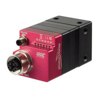
Photon Focus MV0 3D06 Series User Manual (129 pages)
CMOS Camera with GigE Interface
Brand:
Photon Focus
| Category:
Digital Camera
| Size: 5.59 MB
Table of Contents
Table of Contents
3
1 Preface
9
Important Notice
9
About Photonfocus
10
Contact
10
Sales Offices
10
Further Information
10
Legend
11
2 Introduction
13
Camera Naming Convention
13
Camera List
13
3 Product Specification 3.1 Introduction
15
Feature Overview
17
Technical Specification
18
Absolute Maximum Ratings
19
Electrical Characteristics
19
Spectral Response
19
4 Image Acquisition
21
Overview
21
Vocabulary
21
Structure
21
Image Acquisition, Frame and Exposure Control Parameters
22
Image Acquisition, Frame and Exposure Trigger
23
Image Acquisition, Frame and Exposure Status
23
Acquisition Control
24
Acquisition Start and Stop Commands, Acquisition Mode and Acquisition Frame Count
24
Acquisition Frame Rate and Acquisition Frame Rate Enable
24
Acquisition Start Trigger
25
Acquisition End Trigger
26
Acquisition Control Output Signals
26
Frame Control
27
Frame Start Trigger
27
Frame Burst Start Trigger
27
Frame Burst End Trigger
28
Frame Control Output Signals
29
Exposure Control
30
Exposure Mode
30
Exposure Start Trigger
30
Exposure End Trigger
30
Exposure Control Output Signals
31
Overlapped Image Acquisition Timing
32
Acquisition-, Frame- and Exposure-Trigger Configuration
34
Trigger Source Selection
34
Trigger Software
35
Trigger Mode
35
Trigger Activation
35
Trigger Divider
36
Trigger Delay
36
Software Signal Pulse and User Output
37
5 Counter & Timer
39
Counter
39
Counter Usage
39
Counter Status
40
Counter Active, -Start and -End Signal
40
Counter Reset
40
Counter Event Source
41
Counter Trigger Source
42
Counter Reset Source
43
Timer
45
Timer Usage
45
Timer Status
45
Timer Active, -Start and -End Signal
46
Timer Reset
46
Timer Trigger Source
46
6 Encoder
49
Encoder Usage
49
Encoder Trigger Output
50
Encoder Status
50
Encoder Reset Source
51
7 O Control
53
Input Signal Path
53
Output Signal Path
54
8 Action Control
55
Action Command Usage
55
Action Control Output
56
9 User Storage
57
10 Image Format Control
59
Region of Interest (ROI) in 2Donly Mode
59
Region of Interest (ROI) in 3D Modes
59
11 Frame Rate
61
Exposure Time Is Dominant
61
Image Size Is Dominant and Limited by the Interface
61
Image Size Is Dominant and Limited by Sensor
61
Maximum Frame Rate in 2Donly Mode
62
Maximum Frame Rate in 3Donly Mode
62
12 High Dynamic Range Mode (HDR)
65
CMOSIS Multi Slope
65
13 Image Data Processing 13.1 Overview
67
Column FPN Correction
68
Enable / Disable the Column FPN Correction
68
Calibration of the Column FPN Correction
68
Storing the Calibration in Permanent Memory
69
Gain and Offset
69
Laser Test Image
69
Features
70
Overview
70
Measuring Principle
70
Laser Line Detection
71
Interpolation Technique
75
Modes
77
Line
77
Data Format
77
Transmitted Data in 2D&3D Mode
79
Transmitted Data in 3Donly Mode
80
10Frame Combine
81
11Peak Filter
83
12Peak Mirror
85
13Absolute Coordinates
85
14High Speed Mode
85
Status Line and Image Information
86
Image Average Value
86
Status Information
86
Camera Type Codes
86
Test Images
89
Ramp
90
Lfsr
90
Troubleshooting Using the LFSR
91
14 Precautions
93
Important Notice
93
15 Hardware Interface
97
Absolute Maximum Ratings
97
Electrical Characteristics
97
Gige Camera Connector
97
Power over Ethernet (Poe)
97
Status Indicator (Gige Cameras)
98
I/O Connector
99
Overview
99
Encoder Interface
100
Single-Ended Line Input
100
Single-Ended Line Output
102
Master / Slave Camera Connection
103
16 Mechanical Considerations
105
Mechanical Interface
105
MV0 Cameras with Gige Interface
105
Optical Interface
106
Cleaning the Sensor
106
17 Troubleshooting
109
No Images Can be Acquired
109
No Acquisition Due to no Triggers
109
18 Standards Compliance
111
Directives and General Standards
111
Country-Specific Information
111
For Customers in the USA
111
For Customers in Canada
112
Pour Utilisateurs Au Canada
112
Life Support Applications
112
19 Warranty
113
Warranty Terms
113
Warranty Claim
113
Breach of Warranty
113
20 Support and Repair
115
Technical Support
115
Repair and Obtaining an RMA Number
115
Temporal Abandoning and Scrapping
115
21 References
117
A Pinouts
119
I/O Connector
119
Gige Connector
119
B Camera Timing
121
Timed Exposure Mode Camera Timing
121
C Use Cases
123
Acquisition
123
Camera Runs in "Free-Running" Mode
123
Camera Runs in "Constant Frame Rate" Mode
123
Camera Runs in Triggered Mode
124
Camera Runs in Burst Triggered Mode
124
Triggered Controlled Exposure Mode
125
Timer
126
Strobe Signal Output
126
Counter
127
Counter Reset
127
Image Counter
127
Advertisement
Photon Focus MV0 3D06 Series User Manual (125 pages)
Brand:
Photon Focus
| Category:
Digital Camera
| Size: 5.57 MB
Table of Contents
Table of Contents
3
1 Preface
7
Important Notice
7
About Photonfocus
8
Contact
8
Sales Offices
8
Further Information
8
Legend
9
2 Introduction
11
Camera Naming Convention
11
Camera List
11
3 Product Specification 3.1 Introduction
13
Feature Overview
15
Technical Specification
16
Absolute Maximum Ratings
18
Electrical Characteristics
18
Spectral Response
19
4 Image Acquisition
21
Overview
21
Vocabulary
21
Structure
21
Image Acquisition, Frame and Exposure Control Parameters
22
Image Acquisition, Frame and Exposure Trigger
23
Image Acquisition, Frame and Exposure Status
23
Acquisition Control
24
Acquisition Start and Stop Commands, Acquisition Mode and Acquisition Frame Count
24
Acquisition Frame Rate and Acquisition Frame Rate Enable
24
Acquisition Start Trigger
25
Acquisition End Trigger
26
Acquisition Control Output Signals
26
Frame Control
27
Frame Start Trigger
27
Frame Burst Start Trigger
27
Frame Burst End Trigger
28
Frame Control Output Signals
29
Exposure Control
30
Exposure Mode
30
Exposure Start Trigger
30
Exposure End Trigger
30
Exposure Control Output Signals
31
Overlapped Image Acquisition Timing
32
Acquisition-, Frame- and Exposure-Trigger Configuration
34
Trigger Source Selection
34
Trigger Software
35
Trigger Mode
35
Trigger Activation
35
Trigger Divider
36
Trigger Delay
36
Software Signal Pulse and User Output
37
5 Counter & Timer
39
Counter
39
Counter Usage
39
Counter Status
40
Counter Active, -Start and -End Signal
40
Counter Reset
40
Counter Event Source
41
Counter Trigger Source
42
Counter Reset Source
43
Timer
45
Timer Usage
45
Timer Status
45
Timer Active, -Start and -End Signal
46
Timer Reset
46
Timer Trigger Source
46
6 Encoder
49
Encoder Usage
49
Encoder Trigger Output
50
Encoder Status
50
Encoder Reset Source
51
7 O Control
53
Input Signal Path
53
Output Signal Path
54
8 Action Control
55
Action Command Usage
55
Action Control Output
56
9 Image Format Control
57
Region of Interest (ROI)
57
10 Frame Rate
59
Exposure Time Is Dominant
59
Image Size Is Dominant and Limited by Interface
59
Image Size Is Dominant and Limited by Sensor
59
Maximum Frame Rate (2Donly Mode)
60
Maximum Frame Rate in 3D Modes
60
11 Image Data Processing 11.1 Overview
63
Column FPN Correction
64
Enable / Disable the Column FPN Correction
64
Calibration of the Column FPN Correction
64
Storing the Calibration in Permanent Memory
65
Gain and Offset
65
Laser Test Image
65
Features
66
Overview
66
Measuring Principle
66
Laser Line Detection
67
Interpolation Technique
71
Modes
73
Data Format
73
Transmitted Data in 2D&3D Mode
75
Transmitted Data in 3Donly Mode
76
Frame Combine
77
10Peak Filter
79
11Peak Mirror
81
12Absolute Coordinates
81
13High Speed Mode
81
Status Line and Image Information
82
Image Average Value
82
Status Information
82
Camera Type Codes
82
Test Images
85
Ramp
86
Lfsr
86
Troubleshooting Using the LFSR
87
12 Precautions
89
Important Notice
89
13 Hardware Interface
93
Absolute Maximum Ratings
93
Electrical Characteristics
93
Gige Camera Connector
93
Power over Ethernet (Poe)
93
Status Indicator (Gige Cameras)
94
I/O Connector
95
Overview
95
Encoder Interface
96
Single-Ended Line Input
96
Single-Ended Line Output
98
Master / Slave Camera Connection
99
14 Mechanical Considerations
101
Mechanical Interface
101
Cameras with Gige Interface
101
Optical Interface
102
Cleaning the Sensor
102
15 Troubleshooting
105
No Images Can be Acquired
105
No Acquisition Due to no Triggers
105
16 Standards Compliance
107
Directives and General Standards
107
Country-Specific Information
107
For Customers in the USA
107
For Customers in Canada
108
Pour Utilisateurs Au Canada
108
Life Support Applications
108
17 Warranty
109
Warranty Terms
109
Warranty Claim
109
Breach of Warranty
109
18 Support and Repair
111
Technical Support
111
Repair and Obtaining an RMA Number
111
Temporal Abandoning and Scrapping
111
19 References
113
A Pinouts
115
I/O Connector
115
Gige Connector
115
B Camera Timing
117
Timed Exposure Mode Camera Timing
117
C Use Cases
119
Acquisition
119
Camera Runs in "Free-Running" Mode
119
Camera Runs in "Constant Frame Rate" Mode
119
Camera Runs in Triggered Mode
120
Camera Runs in Burst Triggered Mode
120
Triggered Controlled Exposure Mode
121
Timer
122
Strobe Signal Output
122
Counter
123
Counter Reset
123
Image Counter
123
Real Time Counter
123
Missed Trigger Counter
124
D Document Revision History
125
Advertisement
Related Products
Photon Focus MV0 CMOSIS Series
Photon Focus MV0-D2048x1088-C01-160-G2
Photon Focus MV0-D2048-C01-160-G2
Photon Focus MV0-D2048x1088-C01-3D06-768-G2
Photon Focus MV0-D2048-C01-3D06-768-G2
Photon Focus Python MV0-D1280-O01-3D06-288-G2
Photon Focus Python MV0-D1984-O01-3D06-576-G2
Photon Focus Python MV0-D2592-O01-3D06-576-G2
Photon Focus CameraLink MV-D1024E-80
Photon Focus MV1-D1024E-160-CL-12
Photon Focus Categories
Digital Camera
Security Camera
Color Camera
Scanner
Accessories
More Photon Focus Manuals
Login
Sign In
OR
Sign in with Facebook
Sign in with Google
Upload manual
Upload from disk
Upload from URL