Table of Contents
Advertisement
Quick Links
Advertisement
Table of Contents

Related Manuals for Photon Focus MV2-D1280-640


Summary of Contents for Photon Focus MV2-D1280-640
-
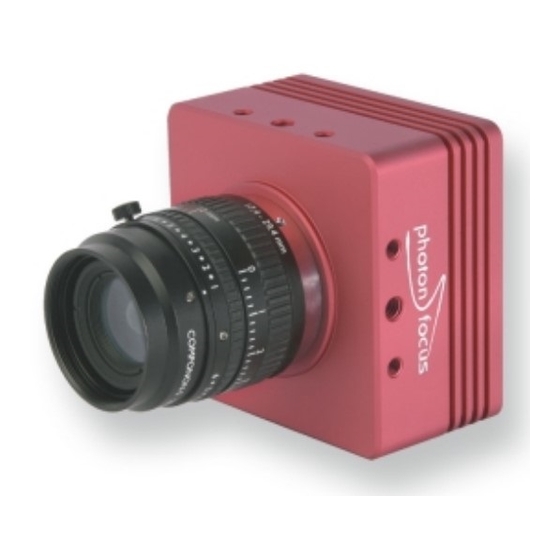
Page 1: User Manual
User Manual MV2-D1280-640 CMOS Area Scan Camera MAN033 07/2008 V1.2... - Page 3 All information provided in this manual is believed to be accurate and reliable. No responsibility is assumed by Photonfocus AG for its use. Photonfocus AG reserves the right to make changes to this information without notice. Reproduction of this manual in whole or in part, by any means, is prohibited without prior permission having been obtained from Photonfocus AG.
-
Page 5: Table Of Contents
Contents 1 Preface 1.1 About Photonfocus ........1.2 Contact . - Page 6 7.1 MV2-D1280-640 ........
-
Page 7: Contents
A Pinouts A.1 Power Supply ......... 79 A.1.1 Power Supply Connector . - Page 8 CONTENTS...
-
Page 9: Preface
Preface 1.1 About Photonfocus The Swiss company Photonfocus is one of the leading specialists in the development of CMOS image sensors and corresponding industrial cameras for machine vision, security & surveillance and automotive markets. Photonfocus is dedicated to making the latest generation of CMOS technology commercially available. -
Page 10: Legend
1 Preface Reproduction of this manual in whole or in part, by any means, is prohibited without prior permission having been obtained from Photonfocus AG. Photonfocus can not be held responsible for any technical or typographical er- rors. 1.5 Legend In this documentation the reader’s attention is drawn to the following icons: Important note. -
Page 11: How To Get Started (Cameralink Full)
How to get started (CameraLink Full) Install a suitable CameraLink Full frame grabber in your PC. To find a compliant frame grabber, please see the frame grabber compatibility list at www.photonfocus.com. Install the frame grabber software. Without installed frame grabber software the camera configuration tool PFRe- mote will not be able to communicate with the camera. - Page 12 2 How to get started (CameraLink Full) Connect a suitable power supply to the provided 7-pole power plug. For the connector assembly see Fig. A.1. The pinout of the connector is shown in Appendix A. Check the correct supply voltage and polarity! Do not exceed the maximum operating voltage of +12V DC (- 10%) to +24V DC (+10%).
- Page 13 Figure 2.2: PFRemote start window 10. Start the camera software PFRemote and choose the communication port. 11. Check the status LED on the rear of the camera. The status LED lights green when an image is being produced, and it is red when serial communication is active.
- Page 14 2 How to get started (CameraLink Full)
-
Page 15: Product Specification
Product Specification 3.1 Introduction The MV2-D1280-640 CMOS camera from Photonfocus is aimed at demanding applications in industrial image processing. It provides an exceptionally high frame rate of up to 488 fps at full resolution of 1280 x 1024 pixels. The camera is built around the MT9M413 CMOS image sensor, developed by Micron. -
Page 16: Technical Specification
2µs Frame Rate ( T = 10 µs) 488 fps Pixel Clock Frequency 82.5 MHz (8-tap mode), 66 MHz (10-tap mode) Camera Taps 8 or 10 Readout mode sequential or simultaneous readout Table 3.2: General specification of the MV2-D1280-640 camera... - Page 17 All specifications apply to 8 bit output and a gain setting of 1 unless stated otherwise. Parameter Value Operating temperature 0°C ... 60°C Camera power supply +12 V DC (+/- 10%) Trigger signal input range +5 .. +15 V DC Strobe signal power supply +5 ..
-
Page 18: Ordering Information
3 Product Specification 3.4 Ordering Information Ordering information is listed in Table 3.4. Item Order Nr. MV2-D1280-640-CL-8 with M42x1.0 thread 602030.100 MV2-D1280-640-CL-8 with C-Mount thread 602030.101 MV2-D1280-640-CL-8 with F-Mount thread 602030.102 Table 3.4: Ordering information 3.5 Frame Grabber Configuration Item... - Page 19 Tap Specifier 8-Tap-Full Tap Number 10-Tap-Full Tap Number Table 3.6: CameraLink tap assignment 3.5 Frame Grabber Configuration...
- Page 20 3 Product Specification CL Transceiver Pin 8-Tap Full Mode 10-Tap Full Mode X-10 X-11 X-12 X-13 X-14 X-15 X-16 X-17 X-18 X-19 X-20 X-21 X-22 X-23 SPARE0 X-24 LVAL0 LVAL0 X-25 FVAL0 FVAL0 X-26 DVAL0 X-27 Table 3.7: CameraLink transceiver X port assignment...
- Page 21 CL Transceiver Pin 8-Tap Full Mode 10-Tap Full Mode Y-10 Y-11 Y-12 Y-13 Y-14 Y-15 Y-16 Y-17 Y-18 Y-19 Y-20 Y-21 Y-22 Y-23 SPARE1 Y-24 LVAL1 Y-25 FVAL1 Y-26 DVAL1 Y-27 LVAL1 Table 3.8: CameraLink transceiver Y port assignment 3.5 Frame Grabber Configuration...
- Page 22 3 Product Specification CL Transceiver Pin 8-Tap Full Mode 10-Tap Full Mode Z-10 Z-11 Z-12 Z-13 Z-14 Z-15 Z-16 Z-17 Z-18 Z-19 Z-20 Z-21 Z-22 Z-23 SPARE2 Z-24 LVAL2 Z-25 FVAL2 Z-26 DVAL2 Z-27 LVAL2 Table 3.9: CameraLink transceiver Z port assignment...
-
Page 23: Functionality
4.1 Image Acquisition 4.1.1 Readout Modes The MV2-D1280-640-CL-8 camera provides two different readout modes: Sequential readout Frame time is the sum of exposure time and readout time. Exposure time of the next image can only start if the readout time of the current image is finished. -
Page 24: Exposure Control
4 Functionality Sequential readout By default the camera continuously delivers images as quickly as possible ("Free-running mode") in the sequential readout mode. Exposure time of the next image can only start if the readout time of the current image is finished. e x p o s u r e r e a d o u t e x p o s u r e... -
Page 25: Maximum Frame Rate
Figure 4.6: Timing in triggered simultaneous readout mode 4.1.3 Maximum Frame Rate The maximum frame rate depends on the exposure time, the readout scheme and the size of the image (see Region of Interest, Section 4.5.1). In most cases, simultaneous readout is the best choice for highest framerate. -
Page 26: Pixel Response
4 Functionality 4.3 Pixel Response 4.3.1 Linear Response Gain x1, x2, x4 Gain x1, x2 and x4 are digital amplifications, which means that the digital image data are multiplied by a factor 1, 2 or 4 respectively, in the camera. Resulting values higher than 255 are clipped to 255. -
Page 27: Grey Level Transformation (Lut)
4.3.2 Grey Level Transformation (LUT) Grey level transformation is remapping of the grey level values of an input image to new values. The look-up table (LUT) is used to convert the greyscale value of each pixel in an image into another grey value. It is typically used to implement a transfer curve for contrast expansion. - Page 28 4 Functionality Gamma The ’Gamma’ mode performs an exponential amplification, configurable in the range from 0.4 to 4.0. Gamma > 1.0 results in an attenuation of the image (see Fig. 4.8), gamma < 1.0 results in an amplification (see Fig. 4.9). γ...
-
Page 29: Test Images
User-defined Look-up Table In the ’User’ mode, the mapping of input to output grey levels can be configured arbitrarily by the user. There is an example file in the PFRemote folder. U s e r L U T y = f ( x ) 8 b i t 1 0 b i t Figure 4.10: Data path through LUT... - Page 30 4 Functionality Figure 4.11: Ramp test image Figure 4.12: LFSR test image In the LFSR (linear feedback shift register) mode the camera generates a constant test pattern containing all grey levels. If the data transmission is error free, the histogram of the received LFSR test pattern will be flat (Fig.
- Page 31 grabber. A possible origin of failure can be a CameraLink cable which exceeds the maxi- mum length or suffers from severe electromagnetic interference. Some CameraLink cables have a predefined direction. Figure 4.13: LFSR test pattern received at the frame grabber and typical histogram for error-free data transmission The LFSR test works only for an image width of 1024, otherwise the histogram will not be flat.
-
Page 32: Image Correction
4.4 Image Correction 4.4.1 Overview The MV2-D1280-640 camera possesses image pre-processing features that compensate for non-uniformities caused by the sensor, the lens or the illumination. This method of improving the image quality is generally known as ’Fixed Pattern Noise (FPN) Correction’, ’Shading Correction’... -
Page 33: Gain Correction
a v e r a g e o f b l a c k r e f e r e n c e p i c t u r e b l a c k r e f e r e n c e o f f s e t c o r r e c t i o n i m a g e m a t r i x... - Page 34 4 Functionality Gain correction is not a straightforward feature. The quality of the grey refer- ence image is crucial for proper gain correction. Gain correction algorithm After configuring the camera with a black and grey reference image, the camera is ready to apply the gain correction: Determine the average value of the grey reference image.
-
Page 35: Corrected Image
Figure 4.18: Proper grey reference image for gain correction 4.4.4 Corrected Image Offset and gain correction can be switched on seperately. The following configurations are possible: • No correction • Offset correction only • Offset and gain correction In addition, the black reference image and grey reference image that are currently stored in the camera RAM can be output. -
Page 36: Reduction Of Image Size
4 Functionality 4.5 Reduction of Image Size With Photonfocus cameras there are several possibilities to focus on the interesting parts of an image, thus reducing the data rate and increasing the frame rate. The most commonly used feature is Region of Interest (ROI). 4.5.1 Region of Interest (ROI) Some applications do not need full image resolution. - Page 37 Exposure time Frame rate 10 µs 486 / 488 fps 100 µs 466 / 488 fps 500 µs 392 / 488 fps 1 ms 328 / 488 fps 2 ms 247 / 488 fps 5 ms 142 / 200 fps 10 ms 83 / 100 fps 12 ms...
-
Page 38: Multiple Regions Of Interest (Mroi)
4 Functionality Parameter Value 10 µs - 1.04 s 15.15 ns Window H Table 4.4: Camera specific values for frame time calculations A calculator for calculating the maximum frame rate is available in the support area of the Photonfocus website (www.photonfocus.com). 4.5.2 Multiple Regions of Interest (MROI) The MV-D1280-640 camera series can handle up to 16 different regions of interest. -
Page 39: External Trigger
4.6 External Trigger An external trigger is an event that starts an exposure. The trigger signal is either generated on the frame grabber (soft-trigger) or comes from an external device such as a light barrier. If a trigger signal is applied to the camera before the earliest time for the next trigger, this trigger will be ignored. -
Page 40: Trigger Delay
4 Functionality P o l a r i t y A c t i v e L o w P o l a r i t y A c t i v e H i g h E x p o s u r e S t a r t E x p o s u r e S t o p E x p o s u r e S t a r t E x p o s u r e S t o p... -
Page 41: Configuration Interface (Cameralink)
4.8 Configuration Interface (CameraLink) A CameraLink camera can be controlled by the user via a RS232 compatible asynchronous serial interface. This interface is contained within the CameraLink interface as shown in Fig. 4.24 and is physically not directly accessible. Instead, the serial communication is usually routed through the frame grabber. - Page 42 4 Functionality...
-
Page 43: Hardware Interface
Hardware Interface 5.1 Connectors 5.1.1 CameraLink Connector The CameraLink cameras are interfaced to external components via • two CameraLink connectors, which are defined by the CameraLink standard as a 26 pin, 0.05" Mini Delta-Ribbon (MDR) connector to transmit configuration, image data and trigger. -
Page 44: Trigger And Strobe Signals
5 Hardware Interface 5.1.3 Trigger and Strobe Signals The power connector contains an external trigger input and a strobe output. The input voltage to the TRIGGER pin must not exceed +15V DC, to avoid damage to the internal optocoupler! In order to use the strobe output, the internal optocoupler must be powered with 5 .. 15 V DC. The STROBE signal is an open-collector output, therefore, the user must connect a pull-up resistor (see Table 5.1) to STROBE_VDD (5 .. -
Page 45: Status Indicator
STROBE_VDD Pull-up Resistor 15 V > 3.9 kOhm 10 V > 2.7 kOhm > 2.2 kOhm > 1.8 kOhm > 1.0 kOhm Table 5.1: Pull-up resistor for strobe output and different voltage levels 5.1.4 Status Indicator Two dual-colour LED’s on the back of the camera gives information about the current status of the CameraLink cameras. - Page 46 5 Hardware Interface Serial communication: A CameraLink camera can be controlled by the user via a RS232 compatible asynchronous serial interface. This interface is contained within the CameraLink interface and is physically not directly accessible. Refer to Section 4.8 for more information.
-
Page 47: Read-Out Timing
5.3 Read-out Timing 5.3.1 Free running Mode Sequential readout timing By default, the camera is in free running mode and delivers images without any external control signals. The sensor is operated in sequential readout mode, which means that the sensor is read out after the exposure time. Then the sensor is reset, a new exposure starts and the readout of the image information begins again. - Page 48 5 Hardware Interface P C L K F r a m e T i m e S H U T T E R E x p o s u r e E x p o s u r e T i m e T i m e F V A L C P R E...
-
Page 49: Constant Frame Rate Mode (Cfr)
Frame time Frame time is the inverse of frame rate. Exposure time Period during which the the pixels are integrating the incoming light. Pixel clock on CameraLink interface. PCLK SHUTTER Internal signal, shown only for clarity. Is ’high’ during the exposure time. - Page 50 5 Hardware Interface E x p o s u r e t i m e R e a d o u t t i m e E x p o s u r e t i m e R e a d o u t t i m e C F R o f f F r a m e t i m e F r a m e t i m e...
-
Page 51: Trigger
5.4 Trigger 5.4.1 Trigger Modes The following sections show the timing diagram for the trigger modes. The signal ExSync denotes the trigger signal that is provided either by the interface trigger or the I/O trigger (see Section 4.6). The other signals are explained in Table 5.4. Camera-controlled Exposure In the camera-controlled trigger mode, the exposure is defined by the camera and is configurable by software. - Page 52 5 Hardware Interface Level-controlled Exposure In the level-controlled trigger mode, the exposure time is defined by the pulse width of the external trigger signal. For an active high trigger signal, the image acquisition begins with the rising edge and stops with the falling edge of the external trigger signal. Then the image is read out.
-
Page 53: Trigger Delay
5.4.2 Trigger Delay The total delay between the trigger edge and the camera exposure consists of the delay in the frame grabber and the camera (Fig. 5.12). Usually, the delay in the frame grabber is relatively large to avoid accidental triggers caused by voltage spikes (see Fig. 5.13). The trigger can also be delayed by the property Trigger.Delay. - Page 54 5 Hardware Interface For the delay in the frame grabber, please ask your frame grabber manufacturer. The camera delay consists of a constant trigger delay and a variable delay (jitter). Trigger delay type Description Trigger delay of the frame grabber, refer to frame grabber manual d FG Variable camera trigger delay: max 15 ns in sequential readout mode, jitter...
-
Page 55: The Pfremote Control Tool
The PFRemote Control Tool 6.1 Overview PFRemote is a graphical configuration tool for Photonfocus cameras. The latest release can be downloaded from the support area of www.photonfocus.com. All Photonfocus cameras can be either configured by PFRemote, or they can be programmed with custom software using the PFLib SDK ([PFLIB]). -
Page 56: Operating System
6 The PFRemote Control Tool 6.2 Operating System The PFRemote GUI is available for Windows OS only. For Linux or QNX operating systems, we provide the necessary libraries to control the camera on request, but there is no graphical user interface available. -
Page 57: Manual Driver Installation (Only Usb 2.0 Model)
6.3.1 Manual Driver Installation (only USB 2.0 Model) If Windows did not automatically install the driver for your USB camera, please proceed as follows: • Open the Device Manager in the Windows Control Panel. • There will be an unknown device called "Silicon Software GmbH microUSB2". •... -
Page 58: Graphical User Interface (Gui)
6 The PFRemote Control Tool 6.4 Graphical User Interface (GUI) PFRemote consists of a main window (Fig. 6.3) and a configuration dialog. In the main window, the camera port can be opened or closed, and log messages are displayed at the bottom. The configuration dialog appears as a sub window as soon as a camera port was opened successfully. -
Page 59: Ports, Device Initialization
6.4.2 Ports, Device initialization After starting PFRemote, the main window as shown in Fig. 6.3 will appear. In the PortBrowser in the upper left corner you will see a list of supported ports. Depending on the configuration, your port names may differ, and not every port may be functional. -
Page 60: Main Buttons
6 The PFRemote Control Tool 6.4.3 Main Buttons The buttons on the right side of the configuration dialog store and reset the camera configuration. Figure 6.4: Main buttons Reset: Reset the camera and load the default configuration. Store as defaults: Store the current configuration in the camera flash memory as the default configuration. -
Page 61: Graphical User Interface (Gui)
Graphical User Interface (GUI) 7.1 MV2-D1280-640 The following sections are grouped according to the tabs in the configuration dialog. Figure 7.1: Frame rate and average value Frame Rate [fps ] Shows the actual frame rate of the camera in frames per second. -
Page 62: Exposure
7 Graphical User Interface (GUI) 7.1.1 Exposure This tab contains exposure settings. Figure 7.2: MV2-D1280-640 Exposure panel Exposure Exposure time [ms ] Configure the exposure time in milliseconds. Constant Frame Rate: When the Constant Frame Rate (CFR) is switched on, the frame rate (number of frames per second) can be varied from almost 0 up to the maximum frame rate. - Page 63 Black Level Offset It may be necessary to adjust the black level offset of the camera. Black Level Offset: Black level offset value. Use this to adjust the black level. 7.1 MV2-D1280-640...
-
Page 64: Window
7 Graphical User Interface (GUI) 7.1.2 Window This tab contains ROI and decimation settings. Figure 7.3: MV2-D1280-640 window panel Region of Interest The region of interest (ROI) is defined as a rectangle (X, Y), (W, H) where X: X - coordinate, starting from 0 in the upper left corner. - Page 65 Y: Y - coordinate of the selected MROI. If Y is set to 1023, this and all further MROI settings will be ignored. H: Height of the selected MROI. H tot: Shows the sum of all MROIs as the total image height. After changing a property, always press Enter in order to make the change active. 7.1 MV2-D1280-640...
-
Page 66: Trigger
7 Graphical User Interface (GUI) 7.1.3 Trigger This tab contains trigger and strobe settings. Figure 7.4: MV2-D1280-640 trigger panel Trigger Trigger Source: Free running: The camera continuously delivers images with a certain configurable frame rate. Interface Trigger: The Trigger signal is applied to the camera by the CameraLink frame grabber or the USB interface respectively. - Page 67 Strobe Delay [ms ] Delay in milliseconds from the input trigger edge to the rising edge of the strobe output signal. Strobe Pulse Width [ms ] The pulse width of the strobe trigger in milliseconds. Strobe signal active low: Define the strobe output to be active high (default) or active low. 7.1 MV2-D1280-640...
-
Page 68: Data Output
7 Graphical User Interface (GUI) 7.1.4 Data Output This tab contains image data settings. Figure 7.5: MV2-D1280-640 data output panel Output Mode Output Mode: Normal: Normal mode. LFSR: Test image. Linear feedback shift register (pseudo-random image). The pattern depends on the grey level resolution. - Page 69 It is typically used to implement a transfer curve for contrast expansion. The MV2-D1280-640 camera performs a 10-to-8-bit mapping, so that 1024 input grey levels can be mapped to 256 output grey levels (0 to 1023 and 0 to 255).
-
Page 70: Correction
7 Graphical User Interface (GUI) 7.1.5 Correction This tab contains correction settings. Figure 7.7: MV2-D1280-640 correction panel Correction Mode This camera has image pre-processing features, that compensate for non-uniformities caused by the sensor, the lens or the illumination. Off: No correction. - Page 71 Calculate: Calculate the correction values into the camera RAM. To make the correction values permanent, use the ’Save to Flash’ button. Save to Flash: Save the current correction values to the internal flash memory. This will overwrite the factory presets. 7.1 MV2-D1280-640...
-
Page 72: Info
This panel shows camera specific information such as type code, serial number and firmware revision of the FPGA and microcontroller and the description of the camera interface. Figure 7.8: MV2-D1280-640 info panel Typecode: Type code of the connected camera. Serial: Serial number of the connected camera. -
Page 73: Mechanical And Optical Considerations
Mechanical and Optical Considerations 8.1 Mechanical Interface The general mechanical data of the cameras are listed in section 3, Table 3.3. During storage and transport, the camera should be protected against vibration, shock, moisture and dust. The original packaging protects the camera adequately from vibration and shock during storage and transport. -
Page 74: Optical Interface
8 Mechanical and Optical Considerations Adapter approx. Extension [mm] C-Mount adapter F-Mount adapter Table 8.1: Dimension extension of the lens mount adapters 8.2 Optical Interface 8.2.1 Mounting the Lens Remove the protective cap from the lens thread of the camera and install the lens. When removing the protective cap or changing the lens, the camera should always be held with the opening facing downwards to prevent dust from falling onto the CMOS sensor. - Page 75 to the surface of the sensor or to the black globe-top material (if present) surrounding the optically active surface during the cleaning process. Product Supplier Remark EAD400D Airduster Electrolube, UK www.electrolube.com Anticon Gold 9"x 9" Wiper Milliken, USA ESD safe and suitable for class 100 environments.
-
Page 76: Compliance
8 Mechanical and Optical Considerations 8.3 Compliance C o m p l i a n c e S t a t e m e n t W e , P h o t o n f o c u s A G , C H - 8 8 5 3 L a c h e n , S w i t z e r l a n d d e c l a r e u n d e r o u r s o l e r e s p o n s i b i l i t y t h a t t h e f o l l o w i n g p r o d u c t s M V - D 1 0 2 4 - 2 8 - C L - 1 0 , M V - D 1 0 2 4 - 8 0 - C L - 8 , M V - D 1 0 2 4 - 1 6 0 - C L - 8... -
Page 77: Warranty
Warranty The manufacturer alone reserves the right to recognize warranty claims. 9.1 Warranty Terms The manufacturer warrants to distributor and end customer that for a period of two years from the date of the shipment from manufacturer or distributor to end customer (the "Warranty Period") that: •... - Page 78 9 Warranty...
-
Page 79: References
References All referenced documents can be downloaded from our website at www.photonfocus.com. CL CameraLink Specification, Rev. 1.1, January 2004 SW002 PFLib Documentation, Photonfocus, October 2007 AN007 Application Note "Camera Acquisition Modes", Photonfocus, March 2004 AN010 Application Note "Camera Clock Concepts", Photonfocus, July 2004 AN021 Application Note "CameraLink", Photonfocus, July 2004 AN026 Application Note "LFSR Test Images", Photonfocus, September 2005... - Page 80 10 References...
-
Page 81: A Pinouts
Pinouts A.1 Power Supply The power supply plugs are available from Binder connectors at www.binder-connector.de. It is extremely important that you apply the appropriate voltages to your camera. Incorrect voltages will damage or destroy the camera. Figure A.1: Power connector assembly A.1.1 Power Supply Connector Connector Type Order Nr. -
Page 82: Cameralink Connectors
A Pinouts " Figure A.2: Power supply plug, 7-pole (rear view of plug, solder side) I/O Type Name Description +12 V DC (- 10%) ... +24 V DC (+10%) Ground RESERVED Do not connect STROBE-VDD +5 .. +15 V DC STROBE Strobe control (opto-isolated) TRIGGER... - Page 83 Name Description SHIELD Shield N_XD0 Negative LVDS Output, CameraLink Data X0 N_XD1 Negative LVDS Output, CameraLink Data X1 N_XD2 Negative LVDS Output, CameraLink Data X2 N_XCLK Negative LVDS Output, CameraLink Clock X N_XD3 Negative LVDS Output, CameraLink Data X3 P_SERTOCAM Positive LVDS Input, Serial Communication to the camera N_SERTOFG Negative LVDS Output, Serial Communication from the camera...
- Page 84 A Pinouts Name Description SHIELD Shield N_YD0 Negative LVDS Output, CameraLink Data Y0 N_YD1 Negative LVDS Output, CameraLink Data Y1 N_YD2 Negative LVDS Output, CameraLink Data Y2 N_YCLK Negative LVDS Output, CameraLink Clock Y N_YD3 Negative LVDS Output, CameraLink Data Y3 100Ω...
-
Page 85: Revision History
Revision History Revision Date Changes 2008-07-10 Syntactic fixes, additional comments on ROI settings Added chapter "Optical Interface" 2008-05-27 Power consumption corrected. Exposure time maximum reduced to 100 ms. Added reference to F-Mount adapter. Added information about shock and vibration tests. Exposure time increment corrected.
Need help?
Do you have a question about the MV2-D1280-640 and is the answer not in the manual?
Questions and answers