Table of Contents
Advertisement
Quick Links
Item Checklist
Completely chec k your package. If you discover damaged or missing items , contact your
retailer.
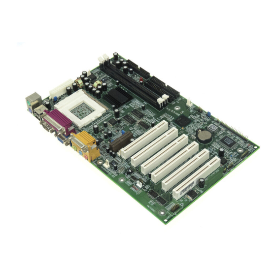
WinneX 3E mainboard
QDI Mainboard Utility CD-ROM
Retention Module
I/O shield
1 IDE ribbon cable
1 floppy ribbon cable
1 9-pin ribbon cable w ith bracket for serial port 2 (manufacturing option)
QDI Serial Product R.M.A. Warranty Card
1 spare jumper cap
User's manual
Notice
The information in this document is subject to change in order to improve reliability, design,
or function w ithout prior notice and does not represent a commitment on the part of this
company. In no event w ill w e be liable for direct, indirect, special, incidental, or consequen-
tial damages arising out of the use or the possibility of such damages.
All trademarks are the property of their respective ow ners.
If you require further information, please visit our w eb-site: "w w w.qdigrp.com".
Advertisement
Table of Contents

Related Manuals for QDI WinneX3E


Summary of Contents for QDI WinneX3E
- Page 1 I/O shield 1 IDE ribbon cable 1 floppy ribbon cable 1 9-pin ribbon cable w ith bracket for serial port 2 (manufacturing option) QDI Serial Product R.M.A. Warranty Card 1 spare jumper cap User’s manual Notice The information in this document is subject to change in order to improve reliability, design, or function w ithout prior notice and does not represent a commitment on the part of this company.
- Page 2 EN 50082-1 Generic immunity standard Part 1: Residential, commercial and light industry European Representative: QDI COMPUTER ( UK ) LTD QDI COMPUTER ( SCANDINAVIA ) A/S QDI SYSTEM HANDEL GMBH QDI COMPUTER ( NETHERLANDS) B. V. QDI COMPUTER (FRANCE) SARL QDI COMPUTER HANDELS GMBH QDI COMPUTER (ESP ANA) S.A.
- Page 3 Declaration of conformity Trade Name: QDI Computer ( U. S . A. ) Inc. M odel Name: WinneX 3E Res ponsible Party: QDI Computer ( U. S. A.) Inc. Address: 41456 Christy Street Fremont, CA 94538 Telephone: (510) 668-4933 Facsimile:...
-
Page 4: Table Of Contents
C O N T E N T S SpeedEasy Quick Setup(English) ............S.1 SpeedEasy Schnell-Installation(Deutsch) ..........S.3 Fácil Y Veloz Rápida Instalación(Español) ...........S.5 Facilité de vitesse Initialisation(Francais) ..........S.7 Setup Della Scheda SpeedEasy(Italiano) ........... S.11 SpeedEasy 快速安装指南(中文繁体) ........... S.13 SpeedEasy 快速安装指南(中文简体) ..........S.15 1. Introduction ............Overview .................... - Page 5 Integrated Peripherals ................31 PC Health Status ..................33 Passw ord Setting ..................35 Boot w ith BIOS Defaults ................. 35 Appendix QDI Mainboard Utility CD-ROM ..........36 RecoveryEasy ............... 37 Introduction ....................37 Operation Process ..................37 FAQ ......................42...
- Page 6 Caution Be sure to unplug the AC power supply before adding or removing expansion cards or other system peripher- als, especially the SDRAM memory, otherwise your mainboard or the system memory might be seriously damaged. The AC power status (ON/OFF) of the system is indicated by the red LED near the two DIMM sockets.
-
Page 7: Speedeasy Quick Setup(English)
WinneX 3E SpeedEasy Quick Setup Pr oced ures : ® ® ® 1. Correctly insert the Intel Pentium III/Pentium II/Celeron™ Slot 1 proces sor. 2. Plug in other configurations and restore the system. Sw itch on pow er to the system and press the <Del> key to enter BIOS Setup. 4. - Page 8 SpeedEasy Type Introduction CPU SpeedEasy Setup Menu Select <CPU SpeedEasy Setup> item from the main menu and enter the sub-menu: Figure - 1 CPU SpeedEasy Setup Menu BIOS pr ovides you w ith a set of basic values for your processor selection instead of the jumper settings.
-
Page 9: Introduction
Chapter 1 Chapter 1 Chapter 1 Introduction Introduction Overview The WinneX 3E green mainboard uti l izes the Intel first generation integrated graphics chipset ® — Intel 810E Chipset, providing a fully compatible, high performance and cost-effective PC/ microATX pl a tform. The new integrated technol o gies, together w ith the softw are configurable AC’97 audio and modem system give customers an advanced, multimedia solution at an ®... - Page 10 Introduction ® Supports Intel Celeron Slot1 Processors at 266/300/333/366/400/433/466/ 500MHz and future processors w ith 66MHz bus speed. Supports 66/100/133MHz host bus speed. The CPU core voltage adjustable from 1.3V to 3.5V automatically through onboard sw itching voltage regulator w ith VID(Voltage ID). Provides onboard 1.5V, 1.8V, 2.5V and 3.3V standby regulator.
- Page 11 Provides onboard 3.3V regulator to support ATX pow er supply w ithout 3.3V output. System status resumes after AC pow er failure. Supports QDI’s i n novations such as SpeedEasy, RecoveryEasy etc. Protects the system BIOS from being attacked by severe virus such as CIH.
-
Page 12: Introduction To New Features
Introduction Introduction to New Features FWH(Firm w ar e Hub) Pr ote ction The BIOS of the mainboar d is ins ide the FWH. Some severe v iruses such as CIH vir us ar e so danger ous that it may overw r ite the BIOS of the mainboar d. If the BIOS has been damaged, the s ys tem w ill be unable to boot. - Page 13 Chapter 1 An ACPI-enabled operating system such as Window s 98 is needed. Navigate to the CD-ROM drive fr om the MS-DOS Command Prompt and enter the follow ing from the Win98 dir ectory on the CD: D:\SETUP /P J (This manual assumes that y our CD-ROM device driv er letter is D:) Window s 98 w ill be installed w ith ACPI enabled.
- Page 14 Introduction Ultra ATA/33 introduc ed CRC (Cyclical Redundancy Check), a new feature of IDE that provides data integrity and reliability. Ultra ATA/66 us es the same process. The CRC value is calc ulated by both the host and the hard dr ive. After the host-request data is sent, the host sends its CRC to the hard drive, and the hard drive compares it to its ow n CRC value.
-
Page 15: Installation Instructions
chapter 2 Chapter 2 Chapter 2 Installation Instructions Installation Instructions This sec tion cover s External Connectors and Jumper Settings . Refer to the mainboard layout chart for locations of all jumpers, external connectors, slots and I/O ports. Further- more, this section lists all necessary connector pin assignments for your referenc e. The particular state of the jumpers, connec tors and ports are illustrated in the follow ing fig- ures. -
Page 16: Line-In Jack, Microphone-In Jack, Speaker-Out Jack And Midi/Joystick Connector
Installation Instruc tions The s erial port UART2 is not available on the back panel. Therefore, w e provide a 9-pin ribbon cable w ith bracket for UART2 port. (manufacturing option) UART2 Line-in Jack, Microphone-in Jack, Speaker-out Jack and MIDI/Joystick Connector The Line-in jack can be connec ted to devices such as a c assette or minidisc player for playback or recording. -
Page 17: Hard Disk Led Connector (Hdled)
chapter 2 Note: If you chang e “ So ft-o ff by PWR- BTTN” fro m de fault “ Ins tant -off” to “ Delay 4 Secs” in the “ POWER MANAGEMENT SET UP” sectio n of the BIOS, the pow er sw it ch should be pre ssed for m ore th an 4 se conds be fore the system pow - ers d ow n. -
Page 18: Infrared Header (Irda)
Installation Instruc tions Infrared Header (IrDA) This c onnector s upports w ir eless trans mitting and receiving. When using this function, configure the s ettings for IR Address, IR Mode and IR IRQ from the “INTEGRATED PERIPHERALS” section of the BIOS. Fan Connector (CPUFAN, CHSFAN) The fan speed of these tw o fans can be detected and view ed in “PC Health”... -
Page 19: Wake-Up On Internal Modem (Wom)
chapter 2 Wake-Up On Internal Modem (WOM) Through the Wake-Up On Internal Modem function, the system w hich is in the pow er-off status c an be pow ered on by a ring signal r eceived fr om the inter nal modem. If this function is to be us ed, be sure an internal modem card w hich supports this function is used. -
Page 20: Sound Connector (Pc-Pci)
If the c onnector has been closed once, the sys tem w ill recor d the s tatus and indicate the chass is has been opened. You can receive this information from QDI ManageEasy softw are. Audio/Modem Riser Interface Connector (AMR) The AMR Interface Connector is the interface betw een the mainboard and the Audi o /Modem Riser card. -
Page 21: Expansion Slots & I/O Ports Description
chapter 2 AMR Interface Connector Expansion Slots & I/O Ports Description Slot / Port Description PCI 1 First PCI slot PCI 2 Second PCI slot PCI3 Third PCI slot IDE 1 Primary IDE port IDE 2 Secondary IDE port AMR slot FLOPPY Floppy Drive Port Jumper Settings... -
Page 22: Clear Cmos (Jcc)
Installation Instruc tions If CPU FSB is set as def ault setting A uto, the sy stem detects the CPU f ront side bus automatic ally. If CPU FSB is s et as 100MHz, the sy stem w ill run at 100MHz even if a processor w ith 66MHz or 133MHz FSB is installed. -
Page 23: Pci 3.3Vsb Voltage Jumper (Jsb)
chapter 2 Disable: Enable: Furthermore in order to implement this function, set “POWER ON Function” to Passw ord and enter the keyboard pow er-on passw ord in the “INTEGRATED PERIPHERALS” section of the BIOS. Save and exit, then pow er off your system. In this case, the pow er button’s pow er- on function has been dis abled. -
Page 24: Enable Usb Device Wake-Up Function (Jusb)
Installation Instruc tions Enable USB Device Wake-up Function (JUSB) The mainboard provides the advanced USB device w ake-up function. The sy stem can be w aken up from its pow er saving including ACPI S3 by activating USB device. Before using this function, set JUSB w ith pin1 &... -
Page 25: Installation Of All Drivers
2 Installation of All Drivers A QDI Mainboard Utility CD-ROM is suppli e d w ith each mainboard. All drivers can be installed from this CD-ROM. Before installing all the drivers, check the system requirements such as the enough system memory (at least 32MB f or Window s 95/98 system or 64MB for Win- dow s 2000 system) and enough disk s pace. -
Page 26: Pc-Cillin 98
Today, it is possible to monitor and manage your complex hardw are from Window s 9X and Window s NT. QDI ManageEasy is a system tool, like a bridge betw een the complex hardw are and OS, used to acces s hardw are status and to execute some control f unctions. -
Page 27: Bios Description
Not e: AWDFLASH.EXE (ver sion>7.07) utility must be used to upgrade the WinneX 3E mainboard BIOS instead of QDI flash utility. So far QDI flash utility —- FLASH.EXE (V 1.3) does not support the Flash EPROM on WinneX 3E mainboard. -
Page 28: Award Bios Description
BIOS Description AWARD BIOS Description Entering Setup Pow er on the computer, w hen the follow ing message briefly appears at the bottom of the screen during the POST (Pow er On Self Test), press <Del> key or simultaneously pres s the <Ctrl> + <Alt> + <Esc> keys, to enter the A WARD BIOS CMOS Setup Utility. Press <Del>... - Page 29 Chapter 3 Figure-2 Standard CMOS Setup Menu For the items marked, press enter, a w indow w ill pop up as show n below. You c an view detailed information or make modifications. Figure-2-1 IDE Primary Master Setup Menu Hard Disk Primary Master/Primary Slave/Secondary Master/Secondary Slave These categori e s identi f y the HDD types of 2 IDE channels i n stalled in the computer system.
- Page 30 BIOS Description The Aw ard BIOS supports 3 HDD modes: NORMAL, LBA and LARGE. NORMAL Generic access mode in w hich neither the BIOS nor the IDE controller w ill make any trans- formation during access ing. The maximum number of c ylinder s, heads and sectors for NORMAL mode are 1024,16 and 63.
- Page 31 Chapter 3 Video Set this field to the type of video display card installed in your system. EGA/ VGA Enhanced Graphics Adapter / Video Graphic Array. For EGA, VGA, SEGA, SVGA, or PGA monitor adapters. CGA 40 Color Graphic Adapter, pow ering up in 40 column mode. CGA 80 Color Graphic Adapter, pow ering up in 80 column mode.
-
Page 32: Cpu Speedeasy Setup
BIOS Description CPU SpeedEasy Setup Figure-3 CPU SpeedEasy Setup Menu The foll owing indicates the options for each item and d escribes their meaning. Item Option Description CPU Speed Jumper Emulation This item is only for users w ho under stand all the CPU par ameters, i.e. -
Page 33: Advanced Bios Features Setup
Chapter 3 Advanced BIOS Features Setup Figure-4 Advanced BIOS Features Menu The following indica tes the options for each item and describes their meaning. Item Option Description ChipAw ayVirus Enabled Guards against boot virus threats early in the On Guard boot cycle, before they have a chance to load into your system, ensuring your computer boots to a clean operating system. - Page 34 BIOS Description Sw ap Floppy Enabled If the system has tw o floppy drives, choose Drive Disabled enable to assign physical drive B to logical drive A and vice-versa. Boot Up Enabled Tests floppy drives to determine w hether they Floppy Seek Disabled have 40 or 80 tracks.
-
Page 35: Advanced Chipset Features Setup
Chapter 3 Advanced Chipset Features Setup Figure-5 Advanced Chipset Features Menu The following ind icate s the options for each item an d describes their meaning . Item Option Description SDRAM CAS Auto Contains the information for SDRAM initialization Latency Time procedure. -
Page 36: Power Management Setup
BIOS Description Power Management Setup Figure-6 Pow er Management Setup Menu The following indica tes the options for each item and describes their meaning. Item Option Description ACPI function Disabled Invalidates ACPI function. Enabled Validates ACPI function. ACPI Suspend S1 Selects the ACPI suspend type. - Page 37 Chapter 3 Does not turn off video w hen entering suspend mode. Suspend Type Stop Grant Selects the Suspend type. PwrOn Suspend MODEM Use IRQ 3, 5, 7, 9, 10, Special w ake-up event for Modem. 11 NA Suspend Mode Disabled The system never enters Suspend mode by timer.
-
Page 38: Pnp/Pci Configuration Setup
BIOS Description PNP/PCI Configuration Setup Figure-7 PNP/PCI Configuration Setup Menu The foll owing indicates the options fo r each item an d describes the ir mean- ing. Item Option Description Reset Configuration Enabled Default is Disabled. Select Enabled to reset Data Extended System Configuration Data ESCD w hen you exit Setup, if you have installed a new... -
Page 39: Integrated Peripherals
Chapter 3 Integrated Peripherals Figure-8 Integrated Peripherals Menu The follow ing indicates the options for each item and describes their meaning. Item Option Description On-Chip Primary/ Enabled On-Chip Primary/Secondary PCI IDE is enabled. Secondary PCI IDE Disabled On-Chip Primary/Secondary PCI IDE is disabled. Mode 0 - 4 Defines the IDE primary/secondary master/ slave Primary/ Secondary... - Page 40 BIOS Description IDE HDD Block Enabled Allow s IDE HDD to read/w rite several sectors at Mode once. Disabled IDE HDD only reads/w rites a sector once. Pow er On BUTTON Uses the pow er button to pow er up the system. Function ONLY Password...
-
Page 41: Pc Health Status
Chapter 3 PC Health Status Figure-9 PC Health Status Menu The follow ing indicates the options for each item and describes their meaning. Item Option Description CPU Warning C/122 An alarm w ill beep w hen the CPU Temperature C/127 temperature reaches the previous setting, C/133 C/122... - Page 42 BIOS Description +3.3V, Termination voltage from the on board regulator +5 V, and VCCVID (CPU) Voltage is the CPU core +12 V, voltage from the on board sw itching Pow er -12 V, Supply. 5V Standby Voltage Shutdow n C/140 The system w ill shut dow n automatically w hen Temperature C/149...
-
Page 43: Password Setting
Chapter 3 Password Setting Superv isor Passw or d has higher priority than User Pas sw ord. You can use Supervisor Passw ord w hen booting the system or entering BIOS Setup to modify all settings. Al s o you can use User Passw or d w hen booting the system or enter ing BIOS Setup but can not modify any setting if Supervisor Passw ord is enabled. -
Page 44: Appendix Qdi Mainboard Utility Cd-Rom
Appendix Appendix Appendix QDI Mainboard Utility CD-ROM QDI Mainboard Utility CD-ROM A QDI Mainboard Utility CD-ROM is supplied w ith each mainboard. The contents used for this mainboard are: ® 1. Intel 810E Chipset Drivers ® A. INF Files for Intel 810E Chipset Contained in the directory \ChipDrv\Intel\Whitney\inf for Window s 95/98. -
Page 45: Recoveryeasy
Introduction: RecoveryEasy , the latest QDI innovation, is able to protect the system f rom being destroyed, by creating a so-called “mirror partition” for a current hard disk partition and backuping all the data to the mirror area. This ideal utility provides disk partition, disk data backup/recovery, CMOS settings backup/recovery and multi-boot functions. - Page 46 RecoveryEasy b. If choosing to install RecoveryEas y on an absolutely clear disk, the utility w ill delete all the previous partitions. c. The passw ord is set as default setting “qdiqdi” after installing RecoveryEasy. 1.1 CREATE PAR Function : Creates a new partition. Lim itation : When no disk space remains or 4 partitions already exist, this button is disabled.
- Page 47 WinneX 3E 1.3 ACTIVE PAR Function : Implements multi-boot function by activating one of the partitions. Lim itation : When no partition exists, this button is disabled. Steps : If there’re tw o or more partitions, choose one of them by pressing F5 key.
- Page 48 RecoveryEasy a. When tw o or more than tw o hard disks are installed on the system, use F5 key to choose the hard disk. Every time users us e F5 key to sw itch the hard disk, the operation result for the previous hard disk is saved. When processing a certain hard disk, F5 key can be us ed to choos e the partition.
- Page 49 WinneX 3E Note: a. During the process of partition backup or recovery, a guage w ill be show n as below, the backup or recovery speed is about 4-5Mbyte/s. See figure-4. figure- 4 Backup Par tition b. If a disk I/O error occurs during the process of partition backup or recovery, this means there’s physical damage on the hard disk, how ever users can ignore it and continue the process.
-
Page 50: Faq
RecoveryEasy 2.6 CHANGE PWD Function : Changes the passw ord to enter RecoveryEasy Partition or Recovery User Interface. Lim itation : None. Steps : Follow the system prompt, input the passw ord no more than 6 characters tw ice. To delete the passw ord, follow the system prompt and press the “Enter”... - Page 51 WinneX 3E Are there any hard disk lim itations of RecoveryEasy? RecoveryEasy supports all kinds of current IDE hard disks and has no limita- tion on the hard disk capacity. RecoveryEasy can not provide its function for some special hard disk types such as SCSI, but it w ill not affect their usage. Are there any OS lim itations of RecoveryEasy? RecoveryEasy supports current operating systems such as DOS, Window s 95/98.
- Page 52 RecoveryEasy before converting can avoid this problem. It’s the same situation as “FAT32 Converter” provi d ed in Window s98. What if partitions be w rongly deleted in RecoveryEasy? If users delete a partition in RecoveryEasy by mistake, they can save it by pressing the Reset button on their system at once.
- Page 53 The Patent for SpeedEasy...
- Page 54 Board Layout of Board Layout of WinneX 3E V1.0 WinneX 3E V1.0...
- Page 55 P/N: 430-01018-401-00 Manual Winne X 3E Ver 1.0...
Need help?
Do you have a question about the WinneX3E and is the answer not in the manual?
Questions and answers