
Subscribe to Our Youtube Channel
Related Manuals for Spectris Particle Measuring Systems IsoAir 310P


Summary of Contents for Spectris Particle Measuring Systems IsoAir 310P
- Page 1 Without measurement there is no control IsoAir® 310P Aerosol Particle Sensor OPERAT I ON S M A N UA L P/N 1000016128...
- Page 2 IsoAir® 310P Aerosol Particle Sensor Operations Manual HEADQUARTERS CHINA JAPAN PUERTO RICO 5475 Airport Blvd +86 21 6113 3600 +81 3 5298 8175 +1 787 718 9096 Boulder, Colorado 80301 USA pmschina@pmeasuring.com pmsjapan@pmeasuring.com pmspuertorico@pmeasuring.com +1 303 443 7100, +1 800 238 1801 FRANCE KOREA SINGAPORE...
-
Page 3: Patent Information
IsoAir 310P Aerosol Particle Sensor Operations Manual P/N 1000016128 Rev E © 2018 by Particle Measuring Systems, Inc. All Rights Reserved ® IsoAir is a trademark of Particle Measuring Systems, Inc. ® Molex is a registered trademark of the Molex Corporation. ®... -
Page 4: Battery Disposal
Battery Disposal Particle Measuring Systems, Inc. encourages users to check with their local municipality for battery recycling. In North America, contact the Rechargeable Battery Recycling Corporation (RBRC) at http://www.call2recycle.org/. In Europe, contact the European Portable Batter4y Association (EPBA) http://www.epbaeurope.net/. Manual Conventions WARNING A warning in the text is used to notify the user of the potential for bodily injury or death. -
Page 5: Ce - Declaration Of Conformity
CE – Declaration of Conformity -Declaration of Conformity Application of Council Directive(s): 2014/30/EU, 2014/35/EU, 2014/53/EU, RoHS 2011/65/EU Standard(s) to which Conformity is Declared: EN 61326-1:2013 Safety EN61010-1: 2010, 3rd, Ed. EN 60825-1: 2014 RTTE ETSI EN 300 328 ETSI EN 301 893 Manufacturer’s Name: Particle Measuring Systems, Inc. -
Page 6: Table Of Contents
Brief Table of Contents Table of Contents - - - - - - - - - - - - - - - - - - - - - - - - - - - - - - - - - - - - - - - - - - - - - - - - - - vii List of Figures - - - - - - - - - - - - - - - - - - - - - - - - - - - - - - - - - - - - - - - - - - - - - - - - - - - - - xi List of Tables - - - - - - - - - - - - - - - - - - - - - - - - - - - - - - - - - - - - - - - - - - - - - - - - - - - - - xiii Chapter 1: Introduction - - - - - - - - - - - - - - - - - - - - - - - - - - - - - - - - - - - - - - - - - - - - 1-1... - Page 7 This page is intentionally left blank. IsoAir 310P Aerosol Particle Sensor Operations Manual...
- Page 8 Table of Contents Patent Information- - - - - - - - - - - - - - - - - - - - - - - - - - - - - - - - - - - - - - - - - - ii Wireless Radio Designators - - - - - - - - - - - - - - - - - - - - - - - - - - - - - - - - - - - ii Quality Statement - - - - - - - - - - - - - - - - - - - - - - - - - - - - - - - - - - - - - - - - - - ii Environmental Information - - - - - - - - - - - - - - - - - - - - - - - - - - - - - - - - - - - ii...
- Page 9 Chapter 3. Configuring for Facility Net - - - - - - - - - - - - - - - - - - - - - - - - - - - - - - - - - - 3-1 Before You Begin - - - - - - - - - - - - - - - - - - - - - - - - - - - - - - - - - - - - - - - - - - - 3-1 Configuring the Sensor - - - - - - - - - - - - - - - - - - - - - - - - - - - - - - - - - - - - - - 3-2 Configuring Instrument Channels - - - - - - - - - - - - - - - - - - - - - - - - - - - - - - 3-6...
- Page 10 ADVERTENCIA - - - - - - - - - - - - - - - - - - - - - - - - - - - - - - - - - - - - - - - - - - - - - - A-1 Hazard Symbols - - - - - - - - - - - - - - - - - - - - - - - - - - - - - - - - - - - - - - - - - - - - A-2 Symboles de risque - - - - - - - - - - - - - - - - - - - - - - - - - - - - - - - - - - - - - - - - - A-2 Warnschilder - - - - - - - - - - - - - - - - - - - - - - - - - - - - - - - - - - - - - - - - - - - - - - A-3...
- Page 11 OPC Server Description - - - - - - - - - - - - - - - - - - - - - - - - - - - - - E-5 Server Browsing - - - - - - - - - - - - - - - - - - - - - - - - - - - - - - - - - - - - - - - - - E-5 Appendix F.
-
Page 12: List Of Figures
List of Figures Chapter 1. Introduction - - - - - - - - - - - - - - - - - - - - - - - - - - - - - - - - - - - - - - - - - - - - - - - - - - - - 1-1 Figure 1-1 IsoAir 310P Particle Sensor - - - - - - - - - - - - - - - - - - - - - - - - - - - - - - - - - - - - - - - 1-2 Chapter 2. - Page 13 Chapter 7. Operations - - - - - - - - - - - - - - - - - - - - - - - - - - - - - - - - - - - - - - - - - - - - - - - - - - - - Chapter 8.
- Page 14 List of Tables Declaration of Conformity - - - - - - - - - - - - - - - - - - - - - - - - - - - - - - - - - - - - - - - - - - - - - - - - - - - - iv Chapter 1.
- Page 15 Appendix E. OPC Configuration and Operation - - - - - - - - - - - - - - - - - - - - - - - - - - - - - - - - - Table E-1 Data Tags - - - - - - - - - - - - - - - - - - - - - - - - - - - - - - - - - - - - - - - - - - - - - - - - - - - - - - E-2 Appendix F.
-
Page 16: Chapter 1: Introduction
Chapter 1 Introduction The IsoAir 310P particle sensor is designed to provide cleanroom and isolator monitoring. When environmental particles go out of specification, the instrument can initiate an alarm to halt operation and help identify the cause. The IsoAir 310P particle sensor generates its own vacuum with an internal pump with HEPA-filtered discharge. -
Page 17: Front Panel
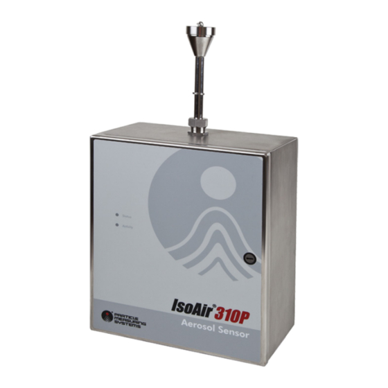
Chapter 1 Introduction Front Panel Front Panel The front panel includes two LED's, the status light and the activity light. Status Light The Status light (three-color LED) indicates the operational status of the instrument and is programmable. Activity Light The Activity LED flashes when particles are detected. Figure 1-1 IsoAir 310P Particle Sensor The top of the enclosure contains the sample inlet port. -
Page 18: Specifications
Specifications Chapter 1 Introduction Specifications Particle Measuring Systems reserves the right to change specifications without notice. Table 1-1 Specifications Channel Options Model 310P: 0.3, 0.5, 1.0, and 5.0 µm. Data output can also be set to 0.5 and 5.0 µm only. Flow rate 1.0 CFM (28.3 LPM). -
Page 19: Accessories
Chapter 1 Introduction Specifications Fuses 250 V, 1 A, 5 x 20 mm, T Laser classification Class 1 per EN60825-1 Internally a Class 3B laser is used per EN60825-1 Temperature: 39 - 95 F (4 – 35 C) Operating environment Humidity: 5 –... -
Page 20: Chapter 2: Unpacking And Installation
Chapter 2 Unpacking and Installation Unpacking the Sensor >> To unpack the sensor: 1 Carefully open the shipping container and remove the IsoAir 310P particle sensor shipment. Inspect each part for damage. 2 If any components are damaged, notify the shipper and Particle Measuring Systems and repackage the unit in the original packing materials. -
Page 21: Sensor Installation
Chapter 2 Unpacking and Installation Sensor Installation Sensor Installation This section includes information to help plan for and install the IsoAir 310P particle sensor system, including: • Selecting a Location on page 2-3 • Setting Up a Remote Sampling System on page 2-4 (optional) •... -
Page 22: Selecting A Location
Sensor Installation Chapter 2 Unpacking and Installation Selecting a Location The location for the IsoAir 310P particle sensor can greatly improve the overall utility of the unit. Consider the following issues when choosing a location for the sensor: • Optimal Sampling – The unit must be mounted close enough to the area it is monitoring that the maximum length of the sample tube is 3 meters (remote mounting only). -
Page 23: Setting Up A Remote Sampling System
Chapter 2 Unpacking and Installation Sensor Installation Setting Up a Remote Sampling System It is not necessary to position the IsoAir 310P enclosure in the air flow to be sampled. If needed, the enclosure can be installed in a remote location. Connect up to 3 meters of sample tubing from the enclosure to an isokinetic probe (ISP), positioning the ISP in the airflow sampling area. -
Page 24: Removing The Electronics Module
Sensor Installation Chapter 2 Unpacking and Installation Removing the Electronics Module WARNING The instrument MUST be disconnected from its power source BEFORE opening the enclosure The electronics module is highly sensitive to electrostatic discharge. Therefore, the electronics module MUST be removed from its stainless steel enclosure before attaching the stainless-steel enclosure to a wall or other vertical surface. -
Page 25: Figure 2-3 Panel Screw Locations
Chapter 2 Unpacking and Installation Sensor Installation 2 Remove the connections to the electronics. See Figure 2-3. WiFi Power (If ordered) Electronic Bench Power Blower (Do Not Disconnect) Ethernet Connection Figure 2-3 Panel Screw Locations 3 Remove the Wi-Fi power connector if that option was ordered. 4 Remove the bench power connector. -
Page 26: Figure 2-4 Accessory Ribbon Cable
Sensor Installation Chapter 2 Unpacking and Installation 6 Remove the accessory board ribbon cable if options were ordered with this unit. Ribbon Cable Connection (If ordered) Figure 2-4 Accessory ribbon cable IsoAir 310P Aerosol Particle Sensor Operations Manual Page 2-7... -
Page 27: Figure 2-5 Blower Screws
Chapter 2 Unpacking and Installation Sensor Installation 7 Loosen the two screws holding the blower in place. Figure 2-5 Blower screws 8 Remove the exhaust tubing connected to the zero count filter. Exhaust Tubing Disconnect Here Figure 2-6 Exhaust filter 9 Grip the electronic cage and lift slightly up and forward to remove the electronic assembly. -
Page 28: Drilling Holes For Conduit Fittings (As Needed)
Sensor Installation Chapter 2 Unpacking and Installation Drilling Holes for Conduit Fittings (as needed) The enclosure is pre-drilled and fitted with cable gland connectors. If a conduit connection is needed, remove the cable gland connectors and use the pre-drilled holes for connecting the conduit. Exhaust Cable Glands... -
Page 29: Required Fasteners
Chapter 2 Unpacking and Installation Sensor Installation Required Fasteners Attach the enclosure to the wall or vertical surface, using fasteners that pass through the provided mounting holes in the back of the enclosure, and then penetrate the wall- framing material. Mounting Mounting Hole... -
Page 30: Prepping The Support Surface
Sensor Installation Chapter 2 Unpacking and Installation Prepping the Support Surface Prepare the support surface for the enclosure installation based on the construction material of the wall or vertical surface. >> To prep the support surface: 1 Using the mounting holes in the back of the enclosure as a template, mark the drill points on the support surface. -
Page 31: Connecting The Electrical Wiring
Chapter 2 Unpacking and Installation Sensor Installation Connecting the Electrical Wiring CAUTION • All wiring must be done in accordance with applicable electrical codes. • A qualified electrician should be used for wiring AC Mains. • This instrument requires an external power disconnect for safety. Electrical wiring should be rated to handle the following current, per instrument: •... -
Page 32: Replacing Fuses
Sensor Installation Chapter 2 Unpacking and Installation Figure 2-10 Connectors Wired to the Terminal Block Replacing Fuses WARNING Disconnect the power cord from its power source. >> Required items: • Replacement fuse: 250 V, 1 A, 5 x 20 mm, T >>... -
Page 33: Figure 2-11 4-20 Ma Input And Solid State Output Connector
Chapter 2 Unpacking and Installation Sensor Installation Figure 2-11 4-20 mA input and solid state output connector Figure 2-12 4-20 mA output connector Page 2-14 IsoAir 310P Aerosol Particle Sensor Operations Manual... - Page 34 Sensor Installation Chapter 2 Unpacking and Installation Ethernet cable connector This cable is required if the IsoAir 310P particle sensor’s output is sent to FacilityPro or Facility Net via your Ethernet network or for OPC or Modbus communications. The cable should be CAT-5 rated or greater to prevent EMI interference.
- Page 35 Chapter 2 Unpacking and Installation Sensor Installation This page is intentionally left blank. Page 2-16 IsoAir 310P Aerosol Particle Sensor Operations Manual...
-
Page 36: Chapter 3: Configuring For Facility Net
Chapter 3 Configuring for Facility Net The IsoAir 310P particle sensor is typically run and monitored from Facility Net. Use this chapter to configure the sensor to communicate with Facility Net via an Ethernet network. The configuration process is usually a one-time event. After you have completed these steps, continue on to Chapter 4 Facility Net Setup for information regarding setting up the software for use with the sensor. -
Page 37: Configuring The Sensor
Chapter 3 Configuring for Facility Net Configuring the Sensor Configuring the Sensor CAUTION As with any network-capable software, do not attempt to connect the IsoAir 310P particle sensor to a network without network administrator permissions. >> To set configuration parameters: 1 Using the straight-through serial cable, connect the computer to the serial port on the IsoAir 310P particle sensor. - Page 38 Configuring the Sensor Chapter 3 Configuring for Facility Net >> To set TCP/IP addresses: 1 At the HyperTerminal session command prompt, execute the following commands as required. set ip aaa.bbb.ccc.ddd sets the IP address in decimal notation. The IP address is in the form aaa.bbb.ccc.ddd.
- Page 39 Chapter 3 Configuring for Facility Net Configuring the Sensor 4 Record the TCP/IP setting for future reference. Unit Serial Number: Date Software Version Set By Address IP Address Multicast Address Net Mask Address Gateway Address Page 3-4 IsoAir 310P Aerosol Particle Sensor Operations Manual...
-
Page 40: Figure 3-1 Example Of The Output From The Help Command
Configuring the Sensor Chapter 3 Configuring for Facility Net Figure 3-1 Example of the output from the help command: Figure 3-2 Example of the output from the status command: IsoAir 310P Aerosol Particle Sensor Operations Manual Page 3-5... -
Page 41: Configuring Instrument Channels
Chapter 3 Configuring for Facility Net Configuring Instrument Channels Configuring Instrument Channels The IsoAir 310P particle sensor can be set up for either the default 4-channel or the 2- channel pharmaceutical mode configuration that only outputs 0.5 and 5.0 µm channels. -
Page 42: Chapter 4: Facility Net Setup
Chapter 4 Facility Net Setup The basic setup of Facility Net for use with the IsoAir 310P particle sensor is included in this section. More detailed information about additional features that enhance data collection and analysis are included in the Facility Net User’s Manual. Before you begin, the IsoAir 310P particle sensor requires that the appropriate TCP/IP address, multicast address, net mask, and gateway values be set into the device by means of its RS-232 (serial) port. -
Page 43: Configuring The Software
Chapter 4 Facility Net Setup Configuring the Software Configuring the Software >> To set parameters: 1 To access the configuration dialog box for the IsoAir 310P particle sensor, click Configure from the top menu, then Instruments from the drop down menu. 2 Click the Add button. -
Page 44: Figure 4-2 Isoair 310P Configuration Dialog Box
Configuring the Software Chapter 4 Facility Net Setup Figure 4-2 IsoAir 310P Configuration dialog box 5 Complete the following fields in the IsoAir 310P Configuration dialog box: • Units • Minimum Interval • Maximum Interval • Name Table 4-1 Configuration dialog box field definitions Units Use the pull-down menu to select the units to display. -
Page 45: Reviewing Channel Configuration
Chapter 4 Facility Net Setup Reviewing Channel Configuration Reviewing Channel Configuration Use this instruction to reference the particle channel thresholds for the IsoAir 310P particle sensor. >> To reference the particle channel thresholds: 1 On the IsoAir 310P Configuration dialog box, click the Channel Configuration tab. NOTE: This information cannot be changed by the user. -
Page 46: Configuring Analog Sensors
Configuring Analog Sensors Chapter 4 Facility Net Setup Configuring Analog Sensors Figure 4-4 Analog Sensors tab in the IsoAir 310P Configuration dialog box >> To configure analog sensors: 1 On the IsoAir 310P Configuration dialog box, click the Analog Sensors tab, if this option was ordered. -
Page 47: Analog Sensors Tab Field Definitions
Chapter 4 Facility Net Setup Configuring Analog Input (Optional) Analog Sensors Tab Field Definitions Name Allows the user to select a meaningful name for the analog data. An example for Analog Input 1 is DAP. Type Each IsoAir 310P particle sensor instrument has a sensor-type associated, which is displayed in the “Type”... -
Page 48: Configuring Run-Time Settings
Configuring Run-Time Settings Chapter 4 Facility Net Setup Configuring Run-Time Settings The Configure dialog box allows you to change selected instrument parameters without re-configuring the system. Limited instrument control and status/error information is also available. Figure 4-5 Configure dialog box Configure Dialog Box Field Definitions Status This field displays the operational status of the IsoAir 310P... -
Page 49: Button Descriptions
Chapter 4 Facility Net Setup Configuring Run-Time Settings Button Descriptions Load Value button Click on this button to make your new selections active. Reset Resets the instrument. Enable Allows the user to enable the instrument. It also, obliquely, indicates the current operating status of the instrument. If the instrument is disabled, all other controls are grayed out. -
Page 50: Configuring 4-20 Ma Output
Chapter 5 4-20 mA Output Option Configuring 4-20 mA Output The 4-20 mA output option provides two channels of data output, as well as a channel for status. Wiring for the output connector is shown in Figure 5-1. CO10 CH 1 CH 2 Status Figure 5-1 Wiring for 4-20 mA output... -
Page 51: Chapter 5 4-20 Ma Output Option
Chapter 5 4-20 mA Output Option Configuring 4-20 mA Output 4-20 mA Out Status Channel (Optional) Only applicable if Option Board 1 is detected. All 4-20 mA outputs are set to 4 mA at start-up. Status output settings Off/default/initialize Idle/StartPump PreSample Tare Sampling - Flow OK Laser OK... -
Page 52: Particle Channel Scale Considerations
Configuring 4-20 mA Output Chapter 5 4-20 mA Output Option Particle Channel Scale Considerations The maximum counts or concentration that can be monitored is the same as the scale factor. In other words, if the scale for channel 1 is set to 100, then the output will be 20 mA, when the counts read 100. - Page 53 Chapter 5 4-20 mA Output Option Configuring 4-20 mA Output This device can be set to auto start via the set inst auto 1 command (see below). Normally the instrument will not take samples until it connects to Facility Net. Use the following serial commands to configure the 4-20 mA signals.
-
Page 54: 4-20 Ma Input
Chapter 6 4-20 mA Input and Solid State Outputs 4-20 mA Input The 4-20 mA input connection allows for connection of 3 4-20 mA inputs. These connections are made via an optional electronics board. See the wiring board shown in Figure 6-1. Figure 6-1 The 4-20 mA input board Solid State Outputs In addition to the 4-20 mA inputs, the same option board can provide 5 solid state... -
Page 55: Chapter 6 4-20 Ma Input And Solid State Outputs
Chapter 6 4-20 mA Input and Solid State Outputs Analog Inputs: Connections and Configuration When in internal digital control mode the 5 digital outputs will be slaved to the status LED as follows: Status Digital Outputs Green 1 ON all others OFF Yellow 2 ON all others OFF... -
Page 56: Configuration
Analog Inputs: Connections and Configuration Chapter 6 4-20 mA Input and Solid State Outputs Configuration When connecting the IsoAir 310P to Facility Net software, the Scale and Offset values must be entered. Different Analog Output sensors can output values in current or voltage, typically 4 –... -
Page 57: Figure 6-2 Facility Net Analog Configuration
Chapter 6 4-20 mA Input and Solid State Outputs Analog Inputs: Connections and Configuration Resolution: Assume a sensor outputs an analog range from 0 – 10 volts. The IsoAir 310P has a Resolution of 12 bits, so the smallest divisible voltage for the 0 – 10 voltage output is (10 –... -
Page 58: Chapter 7: Operations
Chapter 7 Operations Pump Flow Alarm and Shut-off The IsoAir 310P particle sensor uses a sophisticated three-pressure transducer system for monitoring flow. An airflow error will occur if the ISP is capped. If the flow is blocked for the customer-defined time or the default time of 10 minutes, the firmware will turn the pump off and stop data collection. - Page 59 Chapter 7 Operations Detector Board This page is intentionally left blank. Page 7-2 IsoAir 310P Aerosol Particle Sensor Operations Manual...
-
Page 60: Chapter 8: Maintenance
Chapter 8 Maintenance Sterilization of Cleanroom The IsoAir 310P particle sensor is enclosed in a sturdy, stainless steel enclosure and should provide many years of trouble-free performance. Periodically it may be helpful to wipe the case with a clean, lint-free cloth moistened with deionized water or a mild cleanser. - Page 61 Chapter 8 Maintenance Calibration, Service, and Shipping This page is intentionally left blank. Page 8-2 IsoAir 310P Aerosol Particle Sensor Operations Manual...
-
Page 62: Chapter 9: Troubleshooting
Chapter 9 Troubleshooting Problem Symptoms Possible Cause Try... No power No lights Electrical power source Check the electrical wiring. No communications fault Check the external AC disconnect. 24 VDC power was Unplug AC power. Wait at connected with AC least five minutes. Plug AC already on. -
Page 63: Chapter 9 Troubleshooting
Chapter 9 Troubleshooting This page is intentionally left blank. Page 9-2 IsoAir 310P Aerosol Particle Sensor Operations Manual... -
Page 64: Appendix A: International Precautions
Appendix A International Precautions WARNING This instrument is designated as a Class 1 laser product and complies with US 21 CFR 1040.10 and EN 60825-1. Use of controls, or adjustment, or performance of procedures other than those specified in this manual may result in hazardous radiation exposure. AVERTISSEMENT Cet appareil est classé... -
Page 65: Hazard Symbols
Appendix A International Precautions Hazard Symbols Hazard Symbols The meaning of hazard symbols appearing on the equipment is as follows: Symbol Nature of Hazard Attention, consult accompanying documents. Dangerous High Voltage Warning – Laser radiation! Avoid exposure to beam. Symboles de risque Des symboles représentant les risques sont placés sur l'appareil. -
Page 66: Warnschilder
Warnschilder Appendix A International Precautions Warnschilder Die, an dem Gerat angebrachten Warnschilder haben folgende Bedeutungen: Symbol Gefahrenart Achtung! In den beiliegenden Unterlagen nachschlagen Achtung Hochspannung Warnung – Laserstrahlung! Nicht in den Strahl blicken. Simboli di pericolo Il significato dei simboli di pericolo che appaiono sugli strumenti il seguente: Simbolo Natura del pericolo Attenzione. -
Page 67: Simbolos De Peligro
Appendix A International Precautions Simbolos de peligro Simbolos de peligro Los simbolos de peligro que aparecen en el equipo significan: Símbolo Naturaleza del Peligro Atención, consultar los documentos adjuntos. Peligro alto voltaje. Advertencia – ¡Radiación láser! Evite exponerse al rayo. Page A-4 IsoAir 310P Aerosol Particle Sensor Operations Manual... -
Page 68: Appendix B Serial Commands
Appendix B Serial Commands When the network interface is properly configured, these commands are also available via Telnet protocol. When you establish communications with the unit, a prompt will appear. The following commands may be entered at the prompt. data toggles the data dump on and off. -
Page 69: Appendix B Serial Commands
Appendix B Serial Commands set inst 2ch {1 | 0} 2 channel mode xxx set inst Auto {1 | 0} Auto start mode Page B-2 IsoAir 310P Aerosol Particle Sensor Operations Manual... -
Page 70: Appendix C Wi-Fi Configuration
Appendix C Wi-Fi Configuration IsoAir 310P Particle Sensors can be configured to communicate with a Wi-Fi bridge if ordered with this option. Figure C-1 shows an example of a wireless network configuration for IsoAir 310P instruments. Figure C-1 Wireless Network Example IsoAir 310P Aerosol Particle Sensor Operations Manual Page C-1... - Page 71 Appendix C Wi-Fi Configuration The basic settings on the wireless devices are configured for the IsoAir 310P. These are essential for communication. In many installations, IT personnel will be involved with the set up, and they may require more complex configuration settings and different or more secure wireless security.
-
Page 72: Figure C-2 Configuring An Isoair 310P From A Laptop
Appendix C Wi-Fi Configuration Figure C-2 Configuring an IsoAir 310P from a laptop IsoAir 310P Aerosol Particle Sensor Operations Manual Page C-3... -
Page 73: Instructions For Isoair 310P Configuration
Appendix C Wi-Fi Configuration Instructions for IsoAir 310P Configuration Instructions for IsoAir 310P Configuration Router Configuration Before proceeding with the instrument configuration, ensure that the wireless router is configured and working properly. After the router is configured, test it by connecting to it with a laptop. -
Page 74: Figure C-3 Isoair 310P Status Command With Wi-Fi On
Instructions for IsoAir 310P Configuration Appendix C Wi-Fi Configuration > >sta IsoAir_310P version:1.02X Built: Jan 31 2011 MAC Address: 00:60:A6:FF:01:D6 **********Current IP Parameters************* IP Address: 010.254.000.030 Multicast Address: 224.100.100.001 Net Mask: n/a - WiFi Mode Gateway: n/a - WiFi Mode NTP Address: 000.000.000.000 **********After Write IP Parameters*********... -
Page 75: Configure The Wi-Fi Bridge
Appendix C Wi-Fi Configuration Instructions for IsoAir 310P Configuration Configure the Wi-Fi bridge This is done by connecting to the bridge via Ethernet, then using the bridge’s Web Server interface to set addressing and wireless communication parameters. >> To configure the Wi-Fi bridge: 1 Make sure the laptop is set up for DHCP. -
Page 76: Figure C-5 Wi-Fi Bridge Sample Web Page
Instructions for IsoAir 310P Configuration Appendix C Wi-Fi Configuration 4 Start Internet Explorer (or equivalent web browser). Set the URL to the address 192.168.2.1. Figure C-5 on page C-7 shows a sample of the Wi-Fi Web interface. a. A username and password are required to communicate to the Wi-Fi. These are: •... - Page 77 Appendix C Wi-Fi Configuration Instructions for IsoAir 310P Configuration The SSID is the name used to connect to the wireless accesspoint and should be provided by the local IT department. The WLAN Security Type and Key should be provided by the local IT department to allow access to the above SSID.
-
Page 78: Hardware Details
Hardware Details Appendix C Wi-Fi Configuration Hardware Details The Wi-Fi option for the IsoAir 310P instrument is a factory-installed feature. It is installed in the upper left side of the instrument enclosure (see Figure C-6). If option boards are installed in the unit, they are placed on top of the Wi-Fi bridge. CAUTION: Coax is delicate! Reset... -
Page 79: Status Leds
Appendix C Wi-Fi Configuration Hardware Details Status LEDs There are three status LEDs on the bottom side of the Wi-Fi bridge as mounted in the enclosure (see Figure C-6 on page C-9). Their location on the board is illustrated in Figure C-7 on page C-10. -
Page 80: Tips
Tips Appendix C Wi-Fi Configuration Tips Setup Tips and Troubleshooting • The Wi-Fi bridge Web interface has several configuration pages. Most settings can be made on the Express Setup page. There are a large number of parameters which can be adjusted. For the most part, if the parameter is not mentioned in these instructions it does not need to be modified from the factory defaults. -
Page 81: Table C-2 Wireless Data Rate Versus Signal Strength
Appendix C Wi-Fi Configuration Tips • A laptop can be used to provide a rough map of wireless coverage in a plant. Connect the laptop to the wireless sensor network and watch the signal strength bars on the bottom right of the laptop as you perambulate through the sensor installation area. •... -
Page 82: Wi-Fi Sensor Checklist
Wi-Fi Sensor Checklist Appendix C Wi-Fi Configuration Wi-Fi Sensor Checklist Table C-3 Sensor Settings Sensor ID/Description IP Address Net mask Gateway (may be the router address) DNS Server (may be same as Gateway) Wi-Fi SSID Security (e.g., WPA-PSK, WEP-64) Security Password Other Table C-4 Setting Checklist Check... -
Page 83: Wifi Certificate - Fcc
Appendix C Wi-Fi Configuration WiFi Certificate – FCC WiFi Certificate – FCC Page C-14 IsoAir 310P Aerosol Particle Sensor Operations Manual... - Page 84 WiFi Certificate – FCC Appendix C Wi-Fi Configuration IsoAir 310P Aerosol Particle Sensor Operations Manual Page C-15...
-
Page 85: Wifi Certificate - Ioc
Appendix C Wi-Fi Configuration WiFi Certificate – IoC WiFi Certificate – IoC Page C-16 IsoAir 310P Aerosol Particle Sensor Operations Manual... - Page 86 WiFi Certificate – IoC Appendix C Wi-Fi Configuration IsoAir 310P Aerosol Particle Sensor Operations Manual Page C-17...
- Page 87 Appendix C Wi-Fi Configuration WiFi Certificate – IoC Page C-18 IsoAir 310P Aerosol Particle Sensor Operations Manual...
- Page 88 WiFi Certificate – IoC Appendix C Wi-Fi Configuration IsoAir 310P Aerosol Particle Sensor Operations Manual Page C-19...
- Page 89 Appendix C Wi-Fi Configuration WiFi Certificate – IoC This page is intentionally left blank. Page C-20 IsoAir 310P Aerosol Particle Sensor Operations Manual...
-
Page 90: Appendix D Modbus
Appendix D Modbus Communications with the IsoAir 310P can be done via Modbus TCP. The following Modbus register map has comments and notes to help with its intended use. The IsoAir 310P can have one (or none) of two option boards. •... -
Page 91: Input Registers
Appendix D Modbus Input Registers Input Registers The input registers are in two sections: Configuration & Data The configuration section contains: • Map Version • Firmware Version • Product Name • Flow and Volume Scale Factors • Flow Rate • Number of channels (Particle & Analog) •... -
Page 92: Appendix D Modbus
Input Registers Appendix D Modbus Table D-1 Input register – Configuration (Continued) Input Registers Description (Configuration) Comment Notes 30006 string Product Name: Char 06, 07 Serial Number 30007 string Product Name: Char 08, 09 Serial Number 30008 string Product Name: Char 10, 11 Serial Number 30009 string... -
Page 93: Appendix D Modbus
Appendix D Modbus Input Registers Table D-2 Input register – Data Packet (Continued) Input Registers Description (Data Packet) Comment Notes 30211 string Serial Number: Char 14, 15 Serial Number 30212 ushort Device Status (high) Device Status Mask 30213 ushort Device Status (Low) Device Status Mask 30214 ushort... -
Page 94: Holding Registers
Holding Registers Appendix D Modbus Holding Registers Like the coils, spares are in place between the "standard" registers and those that are specific/optional to the IsoAir 310P. The optional IsoAir 310P register is the same as the optional coils (Digital Outputs) but places them all in a single register for ease-of-use. Also the "Mask Write Holding register function"... -
Page 95: Coils
Appendix D Modbus Coils Coils The data collection coil will enable/disable sampling. It will start a sequence of samples if the repeat count has been set. The data available coil is used to both inform the host that data is now available and to delete the next queued data packet (if desired). -
Page 96: Data Packet Processing
Data Packet Processing Appendix D Modbus Data Packet Processing The unit can provide real-time data or queued data or both. There is only one section of input registers assigned for data to handle this information. If the unit is set up to queue data then the data shown is the oldest data in the queue. The data available coil bit will be set if there is data in the queue. -
Page 97: Associated Values For Specific Registry Entries
Appendix D Modbus Associated Values for Specific Registry Entries Associated Values for Specific Registry Entries Table D-5 Associated values for specific registry entries Device Status 0x0001 Data Collection Matches the common coil settings Entries 0x0002 Data Available 0x0004 Data Clear 0x0008 Reset 0x0010... -
Page 98: Appendix E: Opc Configuration And Operation
Appendix E OPC Configuration and Operation OPC (OLE for Process Control) is a communication standard based on Microsoft’s OLE (Object Linking and Embedding) technology that fosters greater interoperability between automation/control applications, field systems/devices, and business/office applications. OPC defines standard objects, methods, and properties of a client/server methodology for real-time information transfer. -
Page 99: Isoair 310P Data Access Tags
Appendix E OPC Configuration and Operation IsoAir 310P Data Access Tags IsoAir 310P Data Access Tags Regardless of the Data Collection System, the IsoAir 310P particle sensor will present a fixed number of data tags that can be grouped by the designated OPC client. All of the tags presented are read-only. -
Page 100: Opc Setup
OPC Setup Appendix E OPC Configuration and Operation Table E-1 Data Tags (Continued) Tag Name Type Units Access Comment Sample.FlowRate VT_R4 cf/min Sample flow rate Sample.Interval VT_R4 Seconds Sample interval Sample.Volume VT_R4 Sample volume Sizes.Ch1 VT_R4 Microns Channel sizes - fixed Sizes.Ch2 VT_R4 Microns... -
Page 101: Opc Server
Appendix E OPC Configuration and Operation OPC Server OPC (OLE for Process Control) is an industry standard created with the collaboration of a number of leading worldwide automation and hardware software suppliers working in cooperation with Microsoft. The organization that manages this standard is the OPC Foundation. -
Page 102: Connecting To The Server
OPC Server Appendix E OPC Configuration and Operation In addition to setting the operation mode, set the IP address, gateway and netmask to suit your networks needs. If the appropriate configurations for your network are not known, contact your IT administrator. The sensor should be set to auto shutoff if the control tags are not utilized. - Page 103 Appendix E OPC Configuration and Operation OPC Server This page is intentionally left blank. Page E-6 IsoAir 310P Aerosol Particle Sensor Operations Manual...
- Page 104 Appendix F Part Name (Pb) (Hg) (Cd) (Cr(VI)) (PBB) (PBDE) SJ/T11363-2006 SJ/T11363-2006 IsoAir 310P Aerosol Particle Sensor Operations Manual Page F-1...
- Page 105 Appendix F This page is intentionally left blank. Page F-2 IsoAir 310P Aerosol Particle Sensor Operations Manual...
Need help?
Do you have a question about the Particle Measuring Systems IsoAir 310P and is the answer not in the manual?
Questions and answers