Sign In
Upload
Manuals
Brands
Spectris Manuals
Accessories
Particle Measuring Systems IsoAir 310P
Spectris Particle Measuring Systems IsoAir 310P Manuals
Manuals and User Guides for Spectris Particle Measuring Systems IsoAir 310P. We have
1
Spectris Particle Measuring Systems IsoAir 310P manual available for free PDF download: Operation Manual
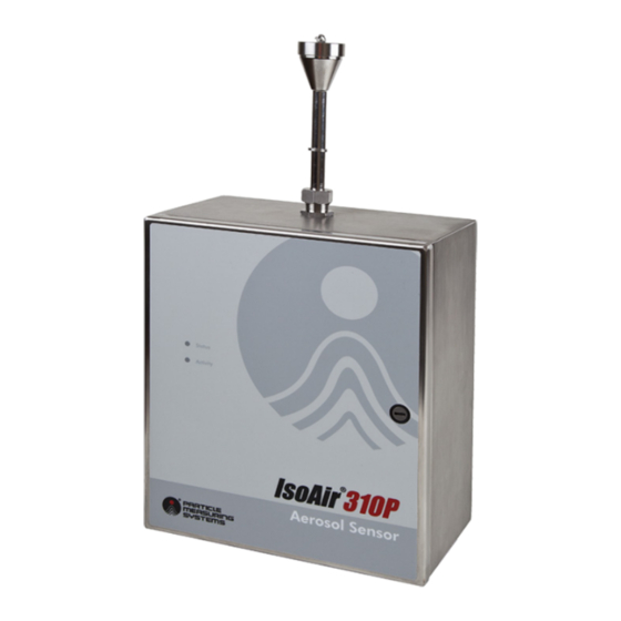
Spectris Particle Measuring Systems IsoAir 310P Operation Manual (105 pages)
Aerosol Particle Sensor
Brand:
Spectris
| Category:
Accessories
| Size: 8 MB
Table of Contents
Patent Information
3
Wireless Radio Designators
3
Quality Statement
3
Environmental Information
3
Battery Disposal
4
Manual Conventions
4
CE - Declaration of Conformity
5
Table of Contents
6
List of Figures
12
Chapter 1: Introduction
16
Chapter 1. Introduction
16
Activity Light
17
Bottom
17
Chapter 1. Introduction
17
Chapter 1 Introduction
18
Table 1-1 Specifications
18
Accessories
19
Options
19
Figure 1-1 Isoair 310P Particle Sensor
17
Front Panel
17
Status Light
17
Top
17
Specifications
18
Chapter 7. Operations
19
Chapter 2: Unpacking and Installation
20
Chapter 2. Unpacking and Installation
20
Not Included
20
Shipment Contents
20
Unpacking the Sensor
20
Sensor Installation
21
Figure 2-2 Knurled Ring on the Top of the Isoair 310P Box
24
Figure 2-3 Panel Screw Locations
25
Figure 2-4 Accessory Ribbon Cable
26
Figure 2-5 Blower Screws
27
Figure 2-6 Exhaust Filter
27
Figure 2-7 Conduit Port Placement, Dual
28
Figure 2-8 Back Panel Showing Mounting Holes
29
Attaching the Enclosure to the Wall
30
Prepping the Support Surface
30
Connecting the Electrical Wiring
31
Figure 2-9 AC Input Wiring Location on Rear
31
Connecting Input-Output Cables
32
Replacing Fuses
32
Figure 2-1 Interior of Isoair 310P Particle Sensor
21
Effective Sampling Probe Placement
22
Selecting a Location
22
Installing the Sensor
23
Setting up a Remote Sampling System
23
Removing the Electronics Module
24
Required Fasteners
29
Drilling Holes for Conduit Fittings (as Needed)
28
Mounting the Sensor
28
Figure 2-10 Connectors Wired to the Terminal Block
32
Figure 2-11 4-20 Ma Input and Solid State Output Connector
33
Figure 2-12 4-20 Ma Output Connector
33
Chapter 3: Configuring for Facility Net
36
Before You Begin
36
Chapter 3. Configuring for Facility Net
36
Table 3-1 Cable Pinouts, RS-232 Straight-Through
36
Configuring the Sensor
37
Table 3-2 Hyperterminal Configuration
37
Figure 3-1 Example of the Output from the Help Command
40
Figure 3-2 Example of the Output from the Status Command
40
Configuring Instrument Channels
41
Setting the Auto-Buffer Size
41
Chapter 4: Facility Net Setup
42
Chapter 4. Facility Net Setup
42
Configuring the Software
43
Figure 4-1 Add Instrument Dialog Box
43
Figure 4-2 Isoair 310P Configuration Dialog Box
44
Table 4-1 Configuration Dialog Box Field Definitions
44
Figure 4-3 Channel Configuration Tab in the Isoair 310P Configuration Dialog Box
45
Figure 4-4 Analog Sensors Tab in the Isoair 310P Configuration Dialog Box
46
Analog Sensors Tab Field Definitions
47
Configuring Analog Input (Optional)
47
Configure Dialog Box Field Definitions
48
Configuring Run-Time Settings
48
Figure 4-5 Configure Dialog Box
48
Button Descriptions
49
Configuring 4-20 Ma Output
50
Configuring Analog Sensors
46
Reviewing Channel Configuration
45
Figure 5-1 Wiring for 4-20 Ma Output
50
Chapter 5 4-20 Ma Output Option
51
Ma out Status Channel (Optional)
51
Status Output Settings
51
Channel Mode
51
Particle Channel Scale Considerations
52
Software Setup for 4-20 Ma Output (Optional)
52
4-20 Ma Input
54
Solid State Outputs
54
Figure 6-1 the 4-20 Ma Input Board
54
Chapter 6 4-20 Ma Input and Solid State Outputs
55
Analog Inputs: Connections and Configuration
55
Connections
55
Table 6-1 Wiring Connections for Current-Output Sensor
55
Table 6-2 Wiring Connections for Voltage-Output Sensor
55
Configuration
56
Figure 6-2 Facility Net Analog Configuration
57
Chapter 7: Operations
58
Chapter 7. Operations
58
Detector Board
58
Pump Flow Alarm and Shut-Off
58
Chapter 8: Maintenance
60
Calibration, Service, and Shipping
60
Chapter 8. Maintenance
60
Sterilization of Cleanroom
60
Chapter 9: Troubleshooting
62
Chapter 9. Troubleshooting
62
Chapter 9 Troubleshooting
63
Appendix A: International Precautions
64
Appendix A. International Precautions
64
Warning
64
Avertissement
64
Warnung
64
Attenzione
64
Advertencia
64
Hazard Symbols
65
Symboles de Risque
65
Appendix A International Precautions
65
Warnschilder
66
Simboli DI Pericolo
66
Simbolos de Peligro
67
Appendix A International Precautions
67
Appendix B Serial Commands
68
Appendix B Serial Commands
69
Figure C-1 Wireless Network Example
70
Appendix C Wi-Fi Configuration
70
Figure C-2 Configuring an Isoair 310P from a Laptop
72
Figure C-3 Isoair 310P Status Command with Wi-Fi on
74
Configure the Wi-Fi Bridge
75
Appendix C. Wi-Fi Configuration
73
Instructions for Isoair 310P Configuration
73
Router Configuration
73
Set the Isoair 310P into Wi-Fi Mode and Select an IP Address for the Instrument
73
Steps for Isoair 310P Wi-Fi Configuration
73
Figure C-4 Wi-Fi Card with Ethernet RJ-45 Female-Female Adapter for PC
75
Figure C-5 Wi-Fi Bridge Sample Web Page
76
Figure C-7 Wi-Fi Bridge Rendering Showing Status Leds
79
Table C-1 LED Status Descriptions
79
Getting Reliable Wireless Networking
80
Setup Tips and Troubleshooting
80
Tips
80
Table C-2 Wireless Data Rate Versus Signal Strength
81
Table C-3 Sensor Settings
82
Table C-4 Setting Checklist
82
Wi-Fi Sensor Checklist
82
Wifi Certificate - FCC
83
Wifi Certificate - Ioc
85
Figure C-6 Wi-Fi Board in Isoair 310P Instrument
78
Hardware Details
78
Reset Button
78
Status Leds
79
Appendix D Modbus
90
Modbus Overview
90
Input Registers
91
Table D-1 Input Register - Configuration
91
Appendix D Modbus
92
Table D-2 Input Register - Data Packet
92
Appendix D Modbus
93
Holding Registers
94
Table D-3 Holding Registers
94
Coils
95
Table D-4 Coils
95
Data Packet Processing
96
Associated Values for Specific Registry Entries
97
Table D-5 Associated Values for Specific Registry Entries
97
Appendix E: OPC Configuration and Operation
98
Appendix E. OPC Configuration and Operation
98
Isoair 310P OPC Identification Data
98
OPC Server Program ID
98
OPC Server Description
98
Isoair 310P Data Access Tags
99
OPC Setup
100
OPC Server
101
Basic Setup
101
Appendix E. OPC Configuration and Operation
101
Connecting to the Server
102
OPC Server Class ID
102
OPC Server Program ID
102
Advertisement
Advertisement
Related Products
Spectris Bruel & Kjaer VIBRO Condition Monitoring 3
Spectris Malvern Panalytical MASTERSIZER 3000
Spectris Malvern Panalytical MASTERSIZER 3000E
Spectris Bruel & Kjaer Vibro 8315
Spectris Bruel & Kjaer Vibro AS-247
Spectris Bruel & Kjaer Vibro AS-477
Spectris Bruel & Kjaer Vibro AS-667
Spectris Bruel & Kjaer Vibro AS-668
Spectris Bruel & Kjaer Vibro ASA-062 ATEX Series
Spectris Bruel & Kjaer Vibro ASA-062/050/0
Spectris Categories
Measuring Instruments
Accessories
Industrial Equipment
Transducer
Cash Counter
More Spectris Manuals
Login
Sign In
OR
Sign in with Facebook
Sign in with Google
Upload manual
Upload from disk
Upload from URL