
Related Manuals for Advantech UNO-2372G V2


Summary of Contents for Advantech UNO-2372G V2
- Page 1 User Manual UNO-2372G V2 電腦 ® ® Intel Celeron Small-Sized Automation Computer with 2 x GbE, 1 x mPCIe, 1 x M.2 B key, 1x M.2 M key, 3 x USB3.2, 1 x USB2.0, 1 x HDMI 1.4, 1 x DP 1.2, and 4 x COM...
- Page 2 No part of this manual may be reproduced, copied, translated, or transmitted in any form or by any means without the prior written permission of Advantech Co., Ltd. The information provided in this manual is intended to be accurate and reliable.
- Page 3 UNO2372GJ2312703-T Product Warranty (2 years) Advantech warrants the original purchaser that each of its products will be free from defects in materials and workmanship for two years from the date of purchase. This warranty does not apply to any products that have been repaired or altered by persons other than repair personnel authorized by Advantech, or products that have been subject to misuse, abuse, accident, or improper installation.
- Page 4 This product has passed the CE test for environmental specifications when shielded cables are used for external wiring. We recommend the use of shielded cables. This type of cable is available from Advantech. Please contact your local supplier for ordering information.
- Page 5 Safety Precautions - Static Electricity Follow these simple precautions to protect yourself from harm and the products from damage. To avoid electrical shock, always disconnect the power from the PC chassis before manual handling. Do not touch any components on the CPU card or other cards while the PC is powered on.
- Page 6 This equipment is not suitable for use in locations where children are likely to be present. If the equipment is used in a manner not specified by the Advantech, the protec- tion provided by the equipment may be impaired. The equipment contains no user-serviceable parts. Do not open, Return to man- ufacturer for servicing.
- Page 7 Ne jamais verser de liquide dans une ouverture. Cela pourrait provoquer un incendie ou un choc électrique. N'ouvrez jamais l'équipement. Pour des raisons de sécurité, l'équipement doit être ouvert uniquement par du personnel qualifié. Si l'une des situations suivantes se présente, faites vérifier l'équipement par le personnel de service: –...
- Page 8 安全指示 請仔細閱讀此安全操作說明。 請妥善保存此用戶手冊供日後參考。 用濕抹布清洗設備前,請確認拔除電源線。請勿使用液體或去污噴霧劑清洗設 備。 對於使用電源線的設備,設備周圍必須有容易接觸到的電源插座。 請勿在潮濕環境中試用設備。 請在安裝前確保設備放置在可靠的平面上,意外摔落可能會導致設備損壞。 設備機殼的開孔適用於空氣對,從而防止設備過熱。請勿覆蓋開孔。 當您連接設備到電源插座前,請確認電源插座的電壓符合要求。 請將電源線佈置在人們不易絆倒的位置,請勿在電源線上覆蓋任何雜物。 請注意設備上所有的警告標示。 如果長時間不使用設備,請拔除與電源插座的連結,避免設備被超標的電壓波動 損壞。 請勿讓任何液體流入通風口,以免引起火灾或短路。 請勿自行打開設備。為了確保您的安全,請透過經認證的工程師來打開設備。 如遇下列情况,請由專業人員維修: 電源線或插頭損壞; 設備內部有液體流入; 設備曾暴露在過度潮濕環境中使用; 設備無法正常工作,或您無法透過用戶手冊來正常工作; 設備摔落或損壞; 設備有明顯外觀損; 請勿將設備儲存在超出建議溫度範圍的環境,即不要低於 -40°C(-40°F)或 高於 85°C(185°F),否則可能會造成設備損壞。 注意:若電池更換不正確,將有爆炸危險。因此,只可以使用製造商推薦的同一 種或者同等型號的電池進行替換。請按照製造商的指示處理舊電池。 根據 IEC 704‐1:1982 規定,操作員所在位置音量不可高於 70 分貝。 限制區域:請勿將設備安裝於限制區域使用。 免責聲明:請安全訓示符合 IEC 704‐1 要求。研華公司對其內容之準確性不承 擔任何法律責任。...
- Page 9 設備名稱:電腦 型號 ( 型式 ):UNO-2372G V2 (系列型號請參見手冊載明型號) Equipment name Type designation (Type) 限用物質及其化學符號 Restricted substances and its chemical symbols 單元 六價鉻 多溴二苯醚 多溴聯苯 鉛 汞 鎘 Unit Hexavalent Polybrominated Polybrominated Lead Mercury Cadmium chromium biphenyls Diphenyl ethers (Pb) (Hg) (Cd)
- Page 10 UNO-2372G_V2 User Manual...
-
Page 11: Table Of Contents
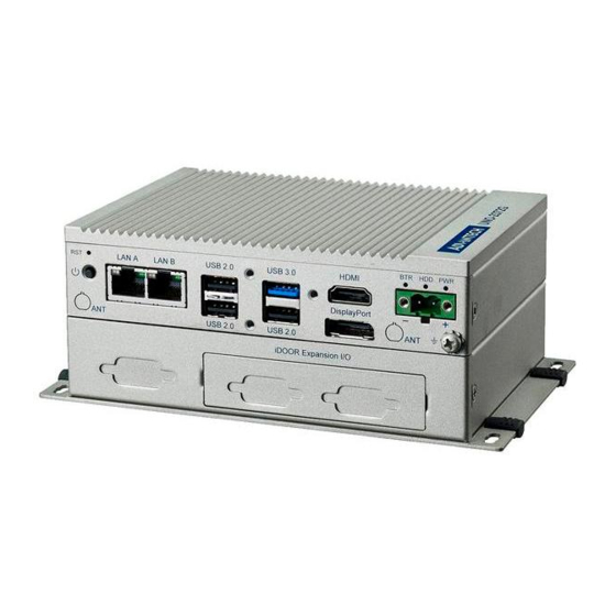
Chapter Hardware Functionality.......7 Introduction ....................8 Figure 2.1 Front Panel of UNO-2372G V2........8 Figure 2.2 Rear Panel of UNO-2372G V2 ........8 Serial Communication Ports..............8 2.2.1 COM Port Interfaces (COM1, COM2, COM3, COM4) ....8 2.2.2 Power Connector ................8 2.2.3... - Page 12 3.6.1 Installing M.2 2242 Card............. 19 3.6.2 Installing M.2 M key 3042 Card ..........20 3.6.3 Installing M.2 B Key 3042 Card ..........20 3.6.4 Installing M.2 B Key 3052 Card ..........20 3.6.5 Installing the mPCIE Module ............21 Antenna Installation (Optional)..............
-
Page 13: Chapter 1 Overview
Chapter Overview This chapter overviews specifica- tions for UNO-2372G V2. Introduction Safety Precautions Accessories Hardware Specifications Dimensions... -
Page 14: Introduction
Introduction Advantech's new UNO-2 series serve as modular Integrated Edge Controllers. They provide configuration flexibility for customers seeking to cost effectively optimize their services. The new integrated Din-rail mounting kit is designed to be more ruggedized and user-friendly, making it a perfect fit for control cabinets. -
Page 15: Packing List
1 x UNO-2372G V2 1 x plug-in block for power wiring 1 x SATA cable (Advantech P/N:1700027329-31) 4 x screws for attaching HDD (Advantech P/N:1930001361) Quick Start Guide 1 x Warranty card If anything is missing or damaged, contact your distributor or sales representative immediately. -
Page 16: Environment
CE, FCC, UL, CCC, BSMI 1.4.6 Extension Kit (Optional) UNO-2372G V2 features a modularized design. Advantech offers two optional 2nd stack extension kits for users to expand the functionality using an Advantech iDoor module. Part number UNO-2372G-EKCE 2nd stack extension kit to support 2 x iDoor module w/ powder... -
Page 17: Dimensions
Dimensions 150 x 105x 35 mm (5.8 x 4.2 x1.4 in) Figure 1.1 UNO-2372G V2 Dimensions Figure 1.2 UNO-2372G V2 Dimensions (with Optional Extension Kit) UNO-2372G_V2 User Manual... - Page 18 UNO-2372G_V2 User Manual...
-
Page 19: Chapter 2 Hardware Functionality
Chapter Hardware Functionality This chapter details setup instruc- tions for UNO-2372G V2’s hard- ware functions. It includes connecting peripherals and indi- cators. Introduction External I/O Connector Internal I/O Connector LED Indicators Reset Buttons Antenna Hole... -
Page 20: Introduction
2.2.2 Power Connector UNO-2372G V2 comes with a Phoenix connector that carries 10 - 36 V external power input, and features reversed wiring protection. Therefore, the system will not accrue damage from reversed polarity of ground lines and power lines. (Please refer to User Manual - Appendix A.1 for pin assignments) -
Page 21: Usb Connector
2.2.4 USB Connector UNO-2372G V2 features 3 x USB ports for Rev. 3.2 specifications and 1 x USB 2.0port. The USB connectors support plug-and-play and hot-swap-ping functionality for external devices. Additionally, this can be enabled/disabled in the BIOS menu. (Please refer to User Manual- Appendix A.3 for pin assignments.) 2.2.5... -
Page 22: M-Key Connector
2.2.12 M.2 M-key Connector There is one M.2 M Key connector for M.2 cards, labeled “M2_M1” on the mother board. This M.2 M key interface is a PCIeX2/ SATA signal. it supports the installation of M.2 2242 storage module. 2.2.13 Nano SIM Slot There’s one Nano SIM slot for supporting LTE function, labeled “CN10”... -
Page 23: Base Unit's Internal Connectors
Base Unit’s Internal Connectors Figure 2.4 Diagram of Connector Locations on UNO-2372G V2 (Top Side) Figure 2.5 Diagram of Key Components Location on UNO-2372G V2 (Bottom Side) UNO-2372G_V2 User Manual... - Page 24 Table 2.1: Key Components, Connectors on Mother Board Category Label Function PWR1 Power button RST1 Reset button HDMI/DP connector LAN1 LAN connector External USB3C1/USB3C2 USB 3.0 connector DCIN1 DC input connector COM port (COM1/2/3/4), BIOS setting RS-232/RS-422/ COM1/2/3/4 RS-485 JCMOS1 Clear CMOS Function PSON2 Power AT/ATX...
-
Page 25: Chapter 3 Initial Setup
Chapter Initial Setup This chapter explains how to Ini- tialize the UNO-2372G V2. Chassis Grounding Connecting Power Open and Close Bottom Cover Installing a 2nd Stack Extension Installing internal component Antenna Installation (Optional) BIOS Settings... -
Page 26: Chassis Grounding
Chassis Grounding The UNO-2372G V2 provides good EMI protection and a stable grounding base and there is an easy-to-connect chassis grounding point for this purpose. Figure 3.1 Chassis Grounding Connection Diagram Use the grounding cable (16 AWG) from the accessory bag to connect the chassis ground with the Earth ground. -
Page 27: Open And Close Bottom Cover
Open and Close Bottom Cover The steps for opening and closing the bottom cover of UNO-2372G V2 are demon- strated below. To open the bottom cover: Remove the 4 rubber feet first, then remove 2 screws from the back cover. - Page 28 To close the bottom cover: To put the back cover on the system, and move the snap on the “close” direction. To close the bottom cover: lock the 2 screws and add the 4 rubber feet back. UNO-2372G_V2 User Manual...
-
Page 29: Installing 2.5" Hdd/Ssd (Height Is Within 7Mm)
Installing 2.5” HDD/SSD (height is within 7mm) Lift the back cover and remove the 4 buttons. Lock the HDD bracket with 4 screws on the back cover. Insert the SATA cable and lock 2 screws on the back cover. UNO-2372G_V2 User Manual... -
Page 30: Installing 2.5" Hdd/Ssd (Height Is Within 7Mm) On 2Nd Stack
Installing 2.5” HDD/SSD (height is within 7mm) on 2nd stack Lock 4 screws on HDD/ SSD, then lock 4 screws on the HDD bracket on 2nd stack, and insert the SATA cable. Lock the 2nd stack on the base unit with 5 screws. UNO-2372G_V2 User Manual... -
Page 31: Installing Internal Component
Put the back cover on the system, and move the snap on the “close” direction, then lock the 2 screws and add the 4 rubber feet back. Installing Internal Component 3.6.1 Installing M.2 2242 Card Remove the back cover and the pre-installed screw, insert the 2242 card and replace the screws. -
Page 32: Installing M.2 M Key 3042 Card
3.6.2 Installing M.2 M key 3042 Card Remove the back cover and the pre-installed screw, insert the 3042 card and replace the screws. 3.6.3 Installing M.2 B Key 3042 Card Remove the back cover and the pre-installed screw, insert the 3042 card and replace the screws. -
Page 33: Installing The Mpcie Module
Remove the back cover and the pre-installed screw, insert the mPCIE card and replace the screws. Antenna Installation (Optional) UNO-2372G V2 reserves pre-cut antenna hole for wireless connection. Follow the steps below for installation the SMA cable and antenna. Remove the back cover and the plug of the antenna’s pre-cutting hole. assem- bly the gasket and the nuts. -
Page 34: Bios Setting
Remind: When the UNO-2372G V2 base unit assemble 4pcs antenna, it can not bun- dle with 2.5 inch SSD/HDD. The 2.5 inch SSD/HDD can be assembled on the double stack SKU with 4pcs antenna. Base unit with 4 antenna Double stack with 4 antenna... -
Page 35: Appendix A System Settings/Pin Assignments
Appendix System Settings/Pin Assignments... -
Page 36: Power Connector (Dcin1)
Power Connector (DCIN1) Table A.1: Power Connector Pin Assignments Signal Description Power IN V+ 10 - 36 V Power IN V- (GND) LAN: Ethernet Connector (LAN1) Table A.2: Ethernet Connector Pin Assignments RJ45 Pin Signal Description In BASE-T: Media Dependent Interface[0]: ... -
Page 37: Usb Connector (Usb3C1/Usb3C2)
USB Connector (USB3C1/USB3C2) A.3.1 USB 3.0 Connector Table A.3: USB 3.0 Connector Pin Assignments Signal Name Description VBUS Power USB 2.0 differential pair Ground for power return StdA_SSRX- SuperSpeed receiver differential pair StdA_SSRX+ GND_DRIAN Ground for signal return StdA_SSTX- SuperSpeed transmitter differential pair StdA_SSTX+ UNO-2372G_V2 User Manual... -
Page 38: Hdmi Connector (Dp1)
HDMI Connector (DP1) Table A.4: Display Port Adapter Cable Pin Assignments Signal Name TMDS1_a_P0 TMDS1_a_N0 TMDS1_a_P1 TMDS1_a_N1 TMDS1_a_P2 TMDS1_a_N2 TMDS1_CLK_a_P TMDS1_CLK_a_N TMDS1_DDCCLK TMDS1_DDCDAT TMDS1_HPD UNO-2372G_V2 User Manual... -
Page 39: M.2 B-Key Connector (M2_B1)
M.2 B-key Connector (M2_B1) Table A.5: M.2 B Key Connector Pin Assignments Signal Name Signal Name M2_SATA1_DET +V3.3_M2 +V3.3_M2 M2_LTE_PWR_OFF# M2_LTE_USB_DP M2_LTE_W1_DISABLE_N M2_LTE_USB_DN +V3.3_M2 Mechanical notch B Mechanical notch B Mechanical notch B Mechanical notch B Mechanical notch B Mechanical notch B Mechanical notch B Mechanical notch B WAKE_ON_WAN#... -
Page 40: M.2 M-Key Connector (M2_M1)
Table A.5: M.2 B Key Connector Pin Assignments M2_SIM1_DET LTE_RST#_P67 +V3.3_M2 +V3.3_M2 +V3.3_M2 M.2 M-Key Connector (M2_M1) Table A.6: M.2 M key Connector Pin Assignments Signal Name Signal Name +V3.3_MKEY +V3.3_MKEY M2E_LED_1# +V3.3_MKEY +V3.3_MKEY +V3.3_MKEY +V3.3_MKEY +V3.3_MKEY UNO-2372G_V2 User Manual... - Page 41 Table A.6: M.2 M key Connector Pin Assignments PCIE_PCH_M2_M1_RX_N2 PCIE_PCH_M2_M1_RX_P2 PCIE_PCH_M2_M1_TX_N2 PCIE_PCH_M2_M1_TX_P2 SATA_SWITCH_M2_M1_RX_N 42 SATA_SWITCH_M2_M1_RX_P 44 SATA_SWITCH_M2_M1_TX_N 48 SATA_SWITCH_M2_M1_TX_P 50 PLTRST_MKEY# M2_E_CLKREQ0# CLK100M_PCH_M2_E1_K_N PCIE_WAKE# CLK100M_PCH_M2_E1_K_P Mechanical notch E Mechanical notch E Mechanical notch E Mechanical notch E Mechanical notch E Mechanical notch E Mechanical notch E Mechanical notch E...
-
Page 42: Mpcie Connector (Minipcie1)
mPCIe Connector (MINIPCIE1) Table A.7: mPCIe Connector Pin Assignments Signal Name Signal Name PCIE_WAKE# +V3.3_MINI +V1.5 PCIEX1_CLKREQ0# CLK100M_PCIEX1_D0- CLK100M_PCIEX1_D0+ WIFI_DISABLE# MINI_PLTRST# SATA0_RX+ +V3.3_MINI SATA0_RX- +V1.5 SATA0_TX- SATA0_TX+ USB2_MPCI_P8- USB2_MPCI_P8+ +V3.3_MINI +V3.3_MINI MPCIE_PWRSEL +V1.5 +V3.3_MINI MSATA#_z_PCIE_SEL UNO-2372G_V2 User Manual... -
Page 43: Com Port Rs232/422/485 Settings
COM Port RS232/422/485 Settings RS232 RS422 RS485 AT/ATX Setting (PSON2) PSON1 can be used for AT/ATX setting. The default setting is ATX mode. See the fol- lowing table for jumper configuration Default UNO-2372G_V2 User Manual... -
Page 44: Jcmos Clear Function
A.10 SW1 for remote Power/Reset button setting. Pin define of SW1 is listed below: Pin Define Signal Name Power button Reset button A.11 JCMOS Clear Function The JCMOS jumper is used to select CMOS clear Enable or Disable. CMOS CLR Jumper Mode Jumper Setting Normal (default) -
Page 45: Tpm 2.0 Bios Setting
The UNO-2372G V2 systems support TPM 2.0 functionality. This can be enabled or disabled in the BIOS menu by following the instructions provided below: Power on the UNO-2372G V2 system and press “Delete” to enter the BIOS con- figuration menu. - Page 46 Then select the “Security Device Support” item. Choose “enable/disable” to enable or disable the TPM 2.0 function (The default setting is to disable this function). UNO-2372G_V2 User Manual...
-
Page 47: Cpu Turbo Mode Bios Setting
A.13 CPU Turbo Mode BIOS Setting The UNO-2372G V2 systems supports CPU Turbo mode. This can be enabled or dis- abled in the BIOS menu by following the instructions: Power on the UNO-2372G V2 system and press “Delete” to enter the BIOS con- figuration menu. - Page 48 UNO-2372G_V2 User Manual...
- Page 49 UNO-2372G_V2 User Manual...
- Page 50 No part of this publication may be reproduced in any form or by any means, such as electronically, by photocopying, recording, or otherwise, without prior written permission from the publisher. All brand and product names are trademarks or registered trademarks of their respective companies. © Advantech Co., Ltd. 2022...
Need help?
Do you have a question about the UNO-2372G V2 and is the answer not in the manual?
Questions and answers