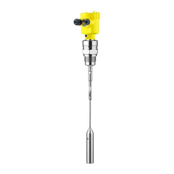
Vega VEGAFLEX 82 Operating Instructions Manual
Tdr sensor for continuous level measurement of bulk solids
Hide thumbs
Also See for VEGAFLEX 82:
- Operating instructions manual (96 pages) ,
- Quick setup manual (20 pages) ,
- Supplementary instructions manual (24 pages)

Related Manuals for Vega VEGAFLEX 82


Summary of Contents for Vega VEGAFLEX 82
- Page 1 Operating Instructions TDR sensor for continuous level measurement of bulk solids VEGAFLEX 82 Profibus PA Rod and cable probe Document ID: 44220...
-
Page 2: Table Of Contents
Parameter adjustment with PACTware ................45 Set up with the quick setup ..................... 46 Saving the parameterisation data ................... 48 Set up with other systems ....................49 DD adjustment programs ....................49 Diagnostics and servicing ....................50 Maintenance ........................50 VEGAFLEX 82 • Profibus PA... - Page 3 Safety instructions for Ex areas Take note of the Ex specific safety instructions for Ex applications. These instructions are attached as documents to each instrument with Ex approval and are part of the operating instructions. Editing status: 2020-01-24 VEGAFLEX 82 • Profibus PA...
-
Page 4: About This Document
Symbols used Document ID This symbol on the front page of this instruction refers to the Docu- ment ID. By entering the Document ID on www.vega.com you will reach the document download. Information, note, tip: This symbol indicates helpful additional infor- mation and tips for successful work. -
Page 5: For Your Safety
During work on and with the device, the required personal protective equipment must always be worn. Appropriate use VEGAFLEX 82 is a sensor for continuous level measurement. You can find detailed information about the area of application in chapter "Product description". -
Page 6: Eu Conformity
The environment management system is certified according to DIN EN ISO 14001. Please help us fulfil this obligation by observing the environmental instructions in this manual: • Chapter "Packaging, transport and storage" • Chapter "Disposal" VEGAFLEX 82 • Profibus PA... -
Page 7: Product Description
• Optionally integrated Bluetooth module The further scope of delivery encompasses: • Documentation – Quick setup guide VEGAFLEX 82 – Instructions for optional instrument features – Ex-specific "Safety instructions" (with Ex versions) – If necessary, further certificates Information: Optional instrument features are also described in this operating instructions manual. - Page 8 Alternatively, you can access the data via your smartphone: • Download the VEGA Tools app from the "Apple App Store" or the "Google Play Store" • Scan the DataMatrix code on the type label of the instrument or •...
-
Page 9: Principle Of Operation
3 Product description Principle of operation Application area The VEGAFLEX 82 is a level sensor with cable or rod probe for con- tinuous level measurement, suitable for applications in bulk solids. Functional principle - High frequency microwave pulses are guided along a steel cable or level measurement a rod. - Page 10 Curved segments: 100 x 100 mm (3.94 … 3.94 in) Centering If you mount the VEGAFLEX 82 in a bypass tube or standpipe, you have to avoid contact to the bypass tube by using a spacer at the probe end.
-
Page 11: Mounting
Prior to setup you have to replace these protective caps with ap- proved cable glands or close the openings with suitable blind plugs. Note: Process conditions For safety reasons, the instrument must only be operated within the permissible process conditions. You can find detailed information on VEGAFLEX 82 • Profibus PA... -
Page 12: Mounting Instructions
Mounting instructions Installation position Mount VEGAFLEX 82 in such a way that the distance to vessel instal- lations or to the vessel wall is at least 300 mm (12 in). In non-metallic vessels, the distance to the vessel wall should be at least 500 mm (19.7 in). - Page 13 Flange Metal sheet Concrete vessel When mounting in thick concrete ceilings, VEGAFLEX 82 should be mounted front flush to the lower edge. In concrete silos, the distance to the wall should be at least 500 mm (20 in). ø >160 mm (ø...
- Page 14 By doing this, you avoid damage to the electronics through inductive coupling. Inflowing medium Do not mount the instruments in or above the filling stream. Make sure that you detect the product surface, not the inflowing product. VEGAFLEX 82 • Profibus PA...
- Page 15 If there is a danger of the rod probe touching the vessel wall, fasten the probe at the bottom end. Keep in mind that measurement is not possible below the fastening point. VEGAFLEX 82 • Profibus PA...
- Page 16 To compensate for the resulting changes in signal runtime, let the instrument determine the probe length automatically. You can find further information in the supplementary instructions of the rod and cable components. VEGAFLEX 82 • Profibus PA...
-
Page 17: Connecting To Power Supply
Note: Prior to setup you have to replace these protective caps with ap- proved cable glands or close the openings with suitable blind plugs. VEGAFLEX 82 • Profibus PA... -
Page 18: Connecting
1 cm (0.4 in) of insulation from the ends of the individual wires 5. Insert the cable into the sensor through the cable entry Fig. 9: Connection steps 5 and 6 Single chamber housing Double chamber housing 6. Insert the wire ends into the terminals according to the wiring plan VEGAFLEX 82 • Profibus PA... -
Page 19: Wiring Plan, Single Chamber Housing
Selection switch for instrument address For external display and adjustment unit Ground terminal for connection of the cable screening Wiring plan, double chamber housing The following illustration applies to the non-Ex, Ex-ia and Ex-d ver- sion. VEGAFLEX 82 • Profibus PA... - Page 20 Selection switch for bus address Connection compartment 6 7 8 Fig. 12: Connection compartment - double chamber housing Voltage supply, signal output For display and adjustment module or interface adapter For external display and adjustment unit Ground terminal for connection of the cable screening VEGAFLEX 82 • Profibus PA...
-
Page 21: Double Chamber Housing With Vegadis-Adapter
Fig. 14: View to the plug connector M12 x 1 Pin 1 Pin 2 Pin 3 Pin 4 Contact pin Colour, connection ca- Terminal, electronics ble in the sensor module Pin 1 Brown Pin 2 White Pin 3 Blue Pin 4 Black VEGAFLEX 82 • Profibus PA... -
Page 22: Wiring Plan - Version Ip66/Ip68, 1 Bar
6 7 8 Fig. 16: Address selection switch Addresses <100 (selection 0), addresses >100 (selection 1) Decade of the address (selection 0 to 9) Unit position of the address (selection 0 to 9) VEGAFLEX 82 • Profibus PA... -
Page 23: Switch-On Phase
The addressing procedure is described in the operating instructions manual "Display and adjustment module. Switch-on phase After connecting VEGAFLEX 82 to the bus system, the device first performs a self-test: • Internal check of the electronics •... -
Page 24: Set Up With The Display And Adjustment Module
The display and adjustment module is powered by the sensor, an ad- ditional connection is not necessary. Fig. 17: Installing the display and adjustment module in the electronics compart- ment of the single chamber housing VEGAFLEX 82 • Profibus PA... -
Page 25: Adjustment System
– Confirm selected menu – Edit parameter – Save value • [->] key: – Change measured value presentation – Select list entry – Select editing position • [+] key: – Change value of the parameter VEGAFLEX 82 • Profibus PA... -
Page 26: Parameter Adjustment - Quick Setup
Any values not confirmed with [OK] will not be saved. Switch-on phase After switching on, the VEGAFLEX 82 carries out a short self-test where the device software is checked. The output signal transmits a fault signal during the switch-on phase. -
Page 27: Parameter Adjustment - Extended Adjustment
"Setup" should be selected one after the other and provided with the correct parameters. If possible, go through the items in the given sequence. The procedure is described below. The following submenu points are available: VEGAFLEX 82 • Profibus PA... - Page 28 Hardware addressing is effective if an address less than 126 is set with the address selection switches on the electronics module of VEGAFLEX 82. In such case, software addressing has no effect - only the set hardware address applies. Software addressing Software addressing is only effective if address 126 or higher is set on the instrument with the address selection switches.
- Page 29 You have the option of choosing the demonstration mode. This mode is only suitable for test and demonstration purposes. In this mode, the sensor ignores the parameters of the application and reacts immedi- ately to any change. VEGAFLEX 82 • Profibus PA...
- Page 30 Adjust the requested percentage value with [+] and store with [OK]. Enter the suitable distance value in m for the empty vessel (e.g. distance from the flange to the probe end) corresponding to the per- VEGAFLEX 82 • Profibus PA...
- Page 31 (too large) value is entered, the existing level will be saved as a false signal. The level would then no longer be detectable in this area. If a false signal suppression has already been created in the sensor, the following menu window appears when selecting "False signal suppression": VEGAFLEX 82 • Profibus PA...
- Page 32 For the socket correction you have to enter the height of the socket above the upper edge of the vessel. If the socket is lower than the up- per edge of the vessel, this value can also be negative. VEGAFLEX 82 • Profibus PA...
- Page 33 AI FB1 - scaling In menu item "Scaling" you define the scaling format on the display and the scaling of the measured level values for 0 % and 100 %. VEGAFLEX 82 • Profibus PA...
- Page 34 In the main menu point "Display", the individual submenu points should be selected one after the other and provided with the correct parameters to ensure the optimum adjustment of the display options. The procedure is described in the following. VEGAFLEX 82 • Profibus PA...
- Page 35 The default setting for the display format is "Automatic". Backlight The integrated background lighting can be switched off via the adjustment menu. The function depends on the strength of the supply voltage, see "Technical data". VEGAFLEX 82 • Profibus PA...
- Page 36 The measurement can be influenced by the process conditions. In this menu item, the measurement reliability of the level measure- ment is displayed in mV. The higher the value, the more reliable the measurement. In another window you can reset the peak value. VEGAFLEX 82 • Profibus PA...
- Page 37 In this menu item you can simulate measured values via the current output. This allows the signal path to be tested, e.g. through down- stream indicating instruments or the input card of the control system. Select the requested simulation variable and set the requested value. VEGAFLEX 82 • Profibus PA...
- Page 38 With the adjustment software PACTware and the PC the high-reso- lution echo curve can be displayed and used later on to assess the quality of the measurement. 6.4.4 Additional adjustments Date/Time In this menu item, the internal clock of the sensor is set. VEGAFLEX 82 • Profibus PA...
- Page 39 Min. adjustment - Level Distance: Probe length - take dead band into account Accept adjustment of the level measurement? Max. adjustment - Interface 100 % Max. adjustment - Interface Distance: 0.000 m(d) - note blocking distances VEGAFLEX 82 • Profibus PA...
- Page 40 Displayed value 1 Filling height Level Displayed value 2 Electronics temperature Backlight Switched on Menu - Diagnosis Menu item Default value Status signals - Function control Switched on Status signals - Out of specification Switched off VEGAFLEX 82 • Profibus PA...
- Page 41 AI FB2 Lo Limit -3.402823E+38 % AI FB2 Hysteresis 0.50 % AI FB2 Fail Safe Mode (behaviour in case of malfunction) Last Valid Out Value (last valid measured value) AI FB2 Fail Safe Value 0.00 % VEGAFLEX 82 • Profibus PA...
- Page 42 The following requirements must be met for a successful transmis- sion: • The data can only be transferred to the same device type, e.g. VEGAFLEX 82 • It must be the same probe type, e.g. rod probe VEGAFLEX 82 • Profibus PA...
- Page 43 6.4.5 Info Device name In this menu, you read out the instrument name and the instrument serial number. Instrument version In this menu item, the hardware and software version of the sensor is displayed. VEGAFLEX 82 • Profibus PA...
-
Page 44: Saving The Parameterisation Data
In the display and adjust- If the instrument is equipped with a display and adjustment module, ment module the parameter adjustment data can be saved therein. The procedure is described in menu item "Copy device settings". VEGAFLEX 82 • Profibus PA... -
Page 45: Setup With Pactware
Further setup steps are described in the operating instructions manu- al "DTM Collection/PACTware" attached to each DTM Collection and which can also be downloaded from the Internet. Detailed descrip- tions are available in the online help of PACTware and the DTMs. VEGAFLEX 82 • Profibus PA... -
Page 46: Set Up With The Quick Setup
The standard version is available as a download under www.vega.com/downloads and "Software". The full version is avail- able on CD from the agency serving you. Set up with the quick setup... - Page 47 2 Extended adjustment Maintenance Quick setup With quick setup you can carry out the parameter adjustment of VEGAFLEX 82 for your application in just a few simple steps. The assistant-driven adjustment includes the basic settings for simple, reliable setup and commissioning. Information: If the function is inactive, then possibly no instrument is connected.
-
Page 48: Saving The Parameterisation Data
7 Setup with PACTware Saving the parameterisation data We recommend documenting or saving the parameterisation data via PACTware. That way the data are available for multiple use or service purposes. VEGAFLEX 82 • Profibus PA... -
Page 49: Set Up With Other Systems
Set up with other systems DD adjustment programs Device descriptions as Enhanced Device Description (EDD) are available for DD adjustment programs such as, for example, AMS↑ and PDM. The files can be downloaded at www.vega.com/downloads under "Software". VEGAFLEX 82 • Profibus PA... -
Page 50: Diagnostics And Servicing
• Switch-on and switch-off times • Status messages (according to NE 107) • Error messages (according to NE 107) The data are read out via a PC with PACTware/DTM or the control system with EDD. VEGAFLEX 82 • Profibus PA... -
Page 51: Status Messages
This status message is always active. It cannot be deactivated by the user. Function check: The instrument is being worked on, the measured value is temporarily invalid (for example during simulation). This status message is inactive by default. VEGAFLEX 82 • Profibus PA... - Page 52 Disconnect operating voltage briefly munication Communication Send instrument for repair error F125 Temperature of the electronics in the Check ambient temperature Bit 7 non-specified range Impermissible Insulate electronics electronics tem- Use instrument with higher temper- perature ature range VEGAFLEX 82 • Profibus PA...
- Page 53 S601 Level echo in the close range not Reduce level Bit 24 available Overfilling 100 % adjustment: Increase value Check mounting socket Remove possible interfering signals in the close range Use coaxial probe VEGAFLEX 82 • Profibus PA...
-
Page 54: Rectify Faults
The operator of the system is responsible for taking suitable meas- tion occurs ures to rectify faults. Fault rectification The first measures are: • Evaluation of fault messages • Checking the output signal • Treatment of measurement errors VEGAFLEX 82 • Profibus PA... - Page 55 Amplitude or position of a false signal has Determine the reason for the changed false changed (e.g. condensation, buildup); false signals, carry out false signal suppression, signal suppression no longer matches ac- e.g. condensation time tual conditions VEGAFLEX 82 • Profibus PA...
- Page 56 100 % dur- range by editing ing emptying With bulk solids use radar sensor with purg- ing air connection or flexible antenna cover time VEGAFLEX 82 • Profibus PA...
- Page 57 Min./max. adjustment not correct Adapt min./max. adjustment too low or too high level Incorrect linearisation curve Adapt linearisation curve Running time error (small measurement Repeat setup error close to 100 %/serious error close to 0 %) time VEGAFLEX 82 • Profibus PA...
- Page 58 Level echo too small Remove contamination on the probe. Af- range during emptying ter having removed the source of the false signals, the false signal suppres- sion must be deleted. Carry out a new false signal suppression time VEGAFLEX 82 • Profibus PA...
-
Page 59: Exchanging The Electronics Module
24 hour service hotline Should these measures not be successful, please call in urgent cases the VEGA service hotline under the phone no. +49 1805 858550. The hotline is also available outside normal working hours, seven days a week around the clock. -
Page 60: Exchange Or Shorten Cable/Rod
1. Mark the requested length with mounted measuring rod. 2. Cable: Loosen the three pins on the gravity weight Cable ø 4: hexagon 3 Cable ø 6, cable ø 8: hexagon 4 3. Cable: remove the pins VEGAFLEX 82 • Profibus PA... -
Page 61: Software Update
The device software can be updated in the following ways: • Interface adapter VEGACONNECT • HART signal • Bluetooth Depending on the method, the following components are required: • Instrument • Voltage supply • Interface adapter VEGACONNECT VEGAFLEX 82 • Profibus PA... -
Page 62: How To Proceed If A Repair Is Necessary
Attach the completed form and, if need be, also a safety data sheet outside on the packaging • Ask the agency serving you to get the address for the return ship- ment. You can find the agency on our homepage. VEGAFLEX 82 • Profibus PA... -
Page 63: Dismount
Pass the instrument directly on to a specialised recycling company and do not use the municipal collecting points. If you have no way to dispose of the old instrument properly, please contact us concerning return and disposal. VEGAFLEX 82 • Profibus PA... -
Page 64: Supplement
Second Line of Defense (optional) Ʋ Supporting material 316L Ʋ Glass potting Borosilicate glass GPC 540 Ʋ Contacts Alloy C22 (2.4602) Ʋ Helium leak rate < 10 mbar l/s Only with Ex-d version. Only with Ex-d version. VEGAFLEX 82 • Profibus PA... - Page 65 Ʋ Cable: ø 11 mm (0.433 in), PA coated 30 KN (6744 lbf) The tensile force of solids are subject of a normal fluctuation range. For this reason, the determined diagram value of the following diagrams must be multiplied with safety factor 2. VEGAFLEX 82 • Profibus PA...
- Page 66 Tensile force in kN (the determined value must be multiplied with safety factor 2) Cable length in m Vessel diameter 12 m (39.37 ft) Vessel diameter 9 m (29.53 ft) Vessel diameter 6 m (19.69 ft) Vessel diameter 3 m (9.843 ft) VEGAFLEX 82 • Profibus PA...
- Page 67 Vessel diameter 3 m (9.843 ft) Thread in gravity weight, e.g. for eye-bolt M 12 (cable version) Torque for exchangeable cable or rod probe (in the process fitting) Ʋ Cable: ø 4 mm (0.157 in) 8 Nm (5.9 lbf ft) VEGAFLEX 82 • Profibus PA...
- Page 68 ø 1 m (3.281 ft), centric mounting, process fit- ting flush with the vessel ceiling Ʋ Reflector metallic, ø 1 m Ʋ Medium Bulk solids - cereals, flour, cement (dielectric con- stant ~2.0) Ʋ Mounting Probe end does not touch the vessel bottom VEGAFLEX 82 • Profibus PA...
- Page 69 Lower dead zone (see following diagrams - grey section) Typical deviation See following diagrams Depending on the mounting conditions, deviations can occur which can be rectified by adapting the adjustment or changing the measured value offset in the DTM service mode. VEGAFLEX 82 • Profibus PA...
- Page 70 Temperature drift - Digital output ±3 mm/10 K relating to the max. measuring range or max. 10 mm (0.394 in) Additional deviation through electromag- < ±10 mm (< ±0.394 in) netic interference acc. to EN 61326 VEGAFLEX 82 • Profibus PA...
- Page 71 Time span after a sudden measuring distance change by max. 0.5 m in liquid applications, max 2 m with bulk solids applications, until the output signal has taken for the first time 90 % of the final value (IEC 61298-2). VEGAFLEX 82 • Profibus PA...
- Page 72 302°F -40°C / -40°F Fig. 35: Ambient temperature - process temperature, standard version Ambient temperature Process temperature (depending on the seal material) Aluminium housing Plastic housing Stainless steel housing, precision casting Stainless steel housing, electropolished VEGAFLEX 82 • Profibus PA...
- Page 73 5 … 9 mm 6 … 12 mm 7 … 12 mm 10 … 14 mm – ● ● – ● Brass, nickel- ● ● ● – – plated Stainless – ● ● – ● steel VEGAFLEX 82 • Profibus PA...
- Page 74 9 … 32 V DC Operating voltage - with Bluetooth 11.6 … 32 V DC switched on Operating voltage U with lighting 13.5 … 32 V DC switched on Number of sensors per DP/PA segment coupler, max. VEGAFLEX 82 • Profibus PA...
-
Page 75: Communication Profibus Pa
Each Profibus instrument gets an unambiguous ident number (ID number) from the Profibus user organisation (PNO). This ID number is also included in the name of the GSD file. Optionally in ad- Galvanic separation between electronics and metal housing parts VEGAFLEX 82 • Profibus PA... - Page 76 The below block diagram below shows which data can be accessed by the PLC. Fig. 37: VEGAFLEX 82: Block diagram with AI FB 1 … AI FB 3 OUT values TB Transducer Block FB 1 … FB 3 Function Block Module of the PA sensors For the cyclic data traffic, VEGAFLEX 82 provides the following modules: • AI FB1 (OUT) – Out value of the AI FB1 after scaling • AI FB2 (OUT)
- Page 77 AI FB1 (OUT) AI FB1 Note: Bytes 6-15 are not used in this example. Data format of the output signal Byte2 Byte1 Byte0 Byte4 Byte3 Status Value (IEEE-754) Fig. 38: Data format of the output signal VEGAFLEX 82 • Profibus PA...
- Page 78 Sensor value < lower limit version not accurate - low limited 0 x 52 uncertain - sensor; con- Sensor value > upper limit version not accurate - high limited 0 x 80 good (non-cascade) - OK VEGAFLEX 82 • Profibus PA...
-
Page 79: Dimensions
Hi-Hi-Alarm tive critical alarm - high limited 11.3 Dimensions The following dimensional drawings represent only an extract of all possible versions. Detailed dimensional drawings can be downloaded at www.vega.com/downloads under "Drawings". Plastic housing ~ 69 mm ~ 84 mm (2.72") (3.31") - Page 80 M20x1,5 M20x1,5/ ½ NPT Fig. 42: Housing version with protection rating IP66/IP68 (1 bar), (with integrated display and adjustment module the housing is 9 mm/0.35 in higher) Aluminium - single chamber Aluminium - double chamber VEGAFLEX 82 • Profibus PA...
- Page 81 Fig. 44: Housing version with protection rating IP66/IP68 (1 bar), (with integrated display and adjustment module the housing is 9 mm/0.35 in higher) Stainless steel single chamber (electropolished) Stainless steel single chamber (precision casting) Stainless steel double chamber housing (precision casting) VEGAFLEX 82 • Profibus PA...
- Page 82 11 Supplement VEGAFLEX 82, cable version ø 4 mm (0.157 in), ø 6 mm (0.236 in), PA coated SW 36 mm (1.42") G ¾ ø 6 mm ø 4 mm (0.24") (0.16") ø 20 mm (0.79") Fig. 45: VEGAFLEX 82, cable ø 4 mm (0.157 in), ø 6 mm (0.236 in) threaded version with gravity weight (all gravity weights with thread M12 for eye-bolt) Sensor length, see chapter "Technical data"...
- Page 83 11 Supplement VEGAFLEX 82, cable version ø 6 mm (0.236 in), ø 11 mm (0.433 in), PA coated SW 55 mm (2.17") G1½ ø 6 mm ø 11 mm (0.24") (0.43") ø 30 mm (1.18") Fig. 46: VEGAFLEX 82, cable ø 6 mm (0.236 in), ø 11 mm (0.433 in) threaded version with gravity weight (all grav- ity weights with thread M12 for eye-bolt) Sensor length, see chapter "Technical data"...
- Page 84 11 Supplement VEGAFLEX 82, rod version ø 16 mm (0.63 in) SW 55 mm (2.17") G1½ ø 16 mm (0.63") Fig. 47: VEGAFLEX 82, rod ø 16 mm (0.63 in), threaded version Sensor length, see chapter "Technical data" Joint - rod VEGAFLEX 82 • Profibus PA...
-
Page 85: Industrial Property Rights
Les lignes de produits VEGA sont globalement protégées par des droits de propriété intellec- tuelle. Pour plus d'informations, on pourra se référer au site www.vega.com. VEGA lineas de productos están protegidas por los derechos en el campo de la propiedad indus- trial. Para mayor información revise la pagina web www.vega.com. - Page 86 False signal suppression 31 Repair 62 Fault Replacement parts – Rectification 54 Fault rectification 54 – Display and adjustment module with heating 10 Functional principle 9 – Rod components 10 – Spacer 10 Reset 39 GSD file 75 VEGAFLEX 82 • Profibus PA...
- Page 87 Sensor characteristics 44 Sensor status 36 Service hotline 59 Simulation 37 Software addressing 23, 28 Special parameters 43 Status bytes PA output value 78 Telegram configuration 77 Type label 7 Type of medium 29 Units 29 VEGAFLEX 82 • Profibus PA...
- Page 88 Subject to change without prior notice © VEGA Grieshaber KG, Schiltach/Germany 2020 VEGA Grieshaber KG Phone +49 7836 50-0 Am Hohenstein 113...
Need help?
Do you have a question about the VEGAFLEX 82 and is the answer not in the manual?
Questions and answers