Vega VEGAFLEX 82 Operating Instructions Manual
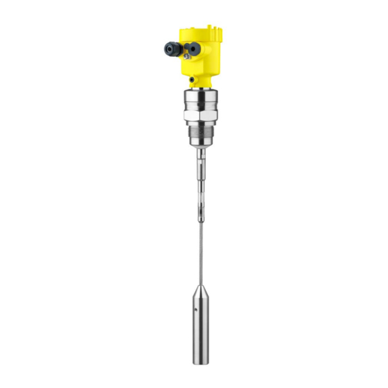
Tdr sensor for continuous level measurement of bulk solids
Hide thumbs
Also See for VEGAFLEX 82:
- Operating instructions manual (92 pages) ,
- Quick setup manual (20 pages) ,
- Supplementary instructions manual (24 pages)

Related Manuals for Vega VEGAFLEX 82


Summary of Contents for Vega VEGAFLEX 82
-
Page 1: Operating Instructions
Operating Instructions TDR sensor for continuous level measurement of bulk solids VEGAFLEX 82 4 … 20 mA/HART - two-wire Rod and cable probe With SIL qualification Document ID: 44222... -
Page 2: Table Of Contents
Insert display and adjustment module ................32 Adjustment system ......................33 Parameter adjustment - Extended adjustment..............35 Saving the parameterisation data ................... 53 Setup with PACTware Connect the PC ......................54 VEGAFLEX 82 • 4 … 20 mA/HART - two-wire... - Page 3 12.4 Trademark ........................90 Safety instructions for Ex areas Take note of the Ex specific safety instructions for Ex applications. These instructions are attached as documents to each instrument with Ex approval and are part of the operating instructions manual. Editing status: 2017-02-02 VEGAFLEX 82 • 4 … 20 mA/HART - two-wire...
-
Page 4: About This Document
This arrow indicates a single action. Sequence of actions Numbers set in front indicate successive steps in a procedure. Battery disposal This symbol indicates special information about the disposal of bat- teries and accumulators. VEGAFLEX 82 • 4 … 20 mA/HART - two-wire... -
Page 5: For Your Safety
During work on and with the device the required personal protective equipment must always be worn. Appropriate use VEGAFLEX 82 is a sensor for continuous level measurement. You can find detailed information about the area of application in chapter "Product description". Operational reliability is ensured only if the instrument is properly used according to the specifications in the operating instructions manual as well as possible supplementary instructions. -
Page 6: Sil Qualification According To Iec 61508
National Electrical Code (ANSI/NFPA 70). Wiring methods must conform to all local and national codes govern- ing the installation, and wiring must be rated for at least +10 °C above the highest expected ambient temperature. VEGAFLEX 82 • 4 … 20 mA/HART - two-wire... -
Page 7: Environmental Instructions
That is why we have introduced an environment management system with the goal of continuously improving company environmental pro- tection. The environment management system is certified according to DIN EN ISO 14001. Please help us fulfil this obligation by observing the environmental instructions in this manual: • Chapter "Packaging, transport and storage" • Chapter "Disposal" VEGAFLEX 82 • 4 … 20 mA/HART - two-wire... -
Page 8: Product Description
Operating instructions and quick setup guide at the time of ship- ment (PDF) • Order-specific sensor data for an electronics exchange (XML) • Test certificate (PDF) - optional Go to "www.vega.com", "VEGA Tools" and "Instrument search". Enter the serial number. Alternatively, you can access the data via your smartphone: VEGAFLEX 82 • 4 … 20 mA/HART - two-wire... -
Page 9: Principle Of Operation
Principle of operation Application area The VEGAFLEX 82 is a level sensor with cable or rod probe for con- tinuous level measurement, suitable for applications in bulk solids. Due to the qualification up to SIL2 or homogeneous redundant up to SIL3 (IEC 61508) the VEGAFLEX 82 is suitable for the use in safety- instrumented systems (SIS). -
Page 10: Packaging, Transport And Storage
The interface adapter VEGACONNECT enables the connection of communication-capable instruments to the USB interface of a PC. For parameter adjustment of these instruments, the adjustment software PACTware with VEGA-DTM is required. VEGAFLEX 82 • 4 … 20 mA/HART - two-wire... - Page 11 3 Product description You can find further information in the operating instructions "Interface adapter VEGACONNECT" (Document-ID 32628). VEGADIS 81 The VEGADIS 81 is an external display and adjustment unit for VEGA plics sensors. ® For sensors with double chamber housing the interface adapter "VEGADIS adapter" is also required for VEGADIS 81.
- Page 12 Curved segments: 100 x 100 mm (3.94 … 3.94 in) You can find further information in the operating instructions manual "Rod and cable components VEGAFLEX 80 series". Centering If you mount the VEGAFLEX 82 in a bypass tube or standpipe, you have to avoid contact to the bypass tube by using a spacer at the probe end. You can find additional information in the operating instructions manual "Centering".
-
Page 13: Mounting
These are mainly: • Active measuring component • Process fitting • Process seal Process conditions in particular are: • Process pressure • Process temperature • Chemical properties of the medium • Abrasion and mechanical influences VEGAFLEX 82 • 4 … 20 mA/HART - two-wire... -
Page 14: Mounting Instructions
Mounting instructions Installation position Mount VEGAFLEX 82 in such a way that the distance to vessel instal- lations or to the vessel wall is at least 300 mm (12 in). In non-metallic vessels, the distance to the vessel wall should be at least 500 mm (19.7 in). - Page 15 4 Mounting Fig. 3: Mounting in non-metallic vessel Flange Metal sheet Concrete vessel When mounting in thick concrete ceilings, VEGAFLEX 82 should be mounted front flush to the lower edge. In concrete silos, the distance to the wall should be at least 500 mm (20 in). ø >160 mm (ø >6.3") Fig.
- Page 16 2 Socket flush - optimum mounting Welding work Before beginning the welding work, remove the electronics module from the sensor. By doing this, you avoid damage to the electronics through inductive coupling. Inflowing medium Do not mount the instruments in or above the filling stream. Make sure that you detect the product surface, not the inflowing product. VEGAFLEX 82 • 4 … 20 mA/HART - two-wire...
- Page 17 If there is a danger of the rod probe touching the vessel wall, fasten the probe at the bottom end. Keep in mind that measurement is not possible below the fastening point. VEGAFLEX 82 • 4 … 20 mA/HART - two-wire...
- Page 18 To compensate for the resulting changes in signal runtime, let the instrument determine the probe length automatically. You can find further information in the supplementary instructions of the rod and cable components. VEGAFLEX 82 • 4 … 20 mA/HART - two-wire...
-
Page 19: Connecting To Power Supply
The signal conditioning instruments VEGAMET and VEGASCAN Connection to signal con- ditioning instruments have digital sensor recognition. When connecting VEGAFLEX 82, an up-to-date version of the signal conditioning instrument software is required. For a software update go to "www.vega.com/downloads" and "Software". -
Page 20: Connecting
3. Loosen compression nut of the cable gland and remove blind plug 4. Remove approx. 10 cm (4 in) of the cable mantle, strip approx. 1 cm (0.4 in) of insulation from the ends of the individual wires VEGAFLEX 82 • 4 … 20 mA/HART - two-wire... - Page 21 When the screwdriver is released, the terminal closes again. You can find further information on the max. wire cross-section under "Technical data - Electromechanical data" 7. Check the hold of the wires in the terminals by lightly pulling on them VEGAFLEX 82 • 4 … 20 mA/HART - two-wire...
-
Page 22: Wiring Plan, Single Chamber Housing
The following illustrations apply to the non-Ex as well as to the Ex-ia version. Electronics compartment 4...20mA 6 7 8 Fig. 12: Electronics compartment - double chamber housing Internal connection to the terminal compartment For display and adjustment module or interface adapter VEGAFLEX 82 • 4 … 20 mA/HART - two-wire... -
Page 23: Wiring Plan, Ex-D-Ia Double Chamber Housing
6 7 8 Fig. 14: Electronics compartment - double chamber housing Internal connection to the terminal compartment For display and adjustment module or interface adapter Internal connection to the plug connector for external display and adjust- ment unit (optional) VEGAFLEX 82 • 4 … 20 mA/HART - two-wire... -
Page 24: Double Chamber Housing With Vegadis-Adapter
Internal plug connection Plug connector M12 x 1 Assignment of the plug connector Fig. 17: View to the plug connector M12 x 1 Pin 1 Pin 2 Pin 3 Pin 4 VEGAFLEX 82 • 4 … 20 mA/HART - two-wire... -
Page 25: Wiring Plan - Version Ip 66/Ip 68, 1 Bar
Additional current output (II) - Voltage supply and signal output (without HART) 3 Ground terminal for connection of the cable screen Supplementary elec- The radio module PLICSMOBILE is an external GSM/GPRS radio tronics - Radio module unit for transmission of measured values and for remote parameter PLICSMOBILE adjustment. VEGAFLEX 82 • 4 … 20 mA/HART - two-wire... -
Page 26: Switch-On Phase
As soon as a plausible measured value is found, the corresponding current is outputted to the signal cable. The value corresponds to the actual level as well as the settings already carried out, e.g. factory setting. VEGAFLEX 82 • 4 … 20 mA/HART - two-wire... -
Page 27: Functional Safety (Sil)
Application area The instrument can be used for point level detection or level measure- ment of liquids and bulk solids in safety-instrumented systems (SIS) according to IEC 61508 and IEC 61511. Take note of the specifica- tions in the Safety Manual. VEGAFLEX 82 • 4 … 20 mA/HART - two-wire... -
Page 28: Safety Concept Of The Parameterization
FDT/DTM standard, e. g. PACTware Note: To operate VEGAFLEX 82, the DTM Collection version 1.67.2 or higher is required. The modification of safety-relevant parameters is only possible with active connection to the instrument (online mode). To avoid possible errors during parameterisation in a non-safe operat-... -
Page 29: Setup Process
Setup - Function test When locking the adjustment, the instrument checks the data of the measurement loop and decides on the basis of the evaluation results if a function test is required. VEGAFLEX 82 • 4 … 20 mA/HART - two-wire... - Page 30 If you have to interrupt the function, you can leave the VEGAFLEX 82 in the respective situation. As long as VEGAFLEX 82 is powered, the display and adjustment module remains in the currently set adjustment menu.
- Page 31 Then you carry out a comparison of two character strings. You must confirm that the character strings are identical. This is used to check the character presentation. Then you confirm that the serial number of your instrument has been carried over correctly. This is used to check device communication. Then, all modified parameters that have to be confirmed are listed. After this process is terminated, the safety function is again ensured. VEGAFLEX 82 • 4 … 20 mA/HART - two-wire...
-
Page 32: Set Up With The Display And Adjustment Module
The display and adjustment module is powered by the sensor, an ad- ditional connection is not necessary. Fig. 21: Installing the display and adjustment module in the electronics compart- ment of the single chamber housing VEGAFLEX 82 • 4 … 20 mA/HART - two-wire... -
Page 33: Adjustment System
Adjustment system Fig. 23: Display and adjustment elements 1 LC display Adjustment keys • Key functions [OK] key: VEGAFLEX 82 • 4 … 20 mA/HART - two-wire... - Page 34 [OK] will not be saved. Switch-on phase After switching on, the VEGAFLEX 82 carries out a short self-test where the device software is checked. The output signal transmits a fault signal during the switch-on phase. The following information is displayed on the display and adjustment module during the startup procedure: •...
-
Page 35: Parameter Adjustment - Extended Adjustment
"OK" key to start the editing. With the "+" key you change the sign and with the "->" key you jump to the next position. You can enter names with max. 19 characters. The character set comprises: • Capital letters from A … Z VEGAFLEX 82 • 4 … 20 mA/HART - two-wire... - Page 36 This mode is only suitable for test and demonstration purposes and must not be used in a safety-instrumented application (SIL). VEGAFLEX 82 • 4 … 20 mA/HART - two-wire...
- Page 37 Adjust the requested percentage value with [+] and store with [OK]. Enter the suitable distance value in m for the empty vessel (e.g. distance from the flange to the probe end) corresponding to the per- centage value. The distance refers tot he sensor reference plane (seal surface of the process fitting). VEGAFLEX 82 • 4 … 20 mA/HART - two-wire...
- Page 38 For the socket correction you have to enter the height of the socket above the upper edge of the vessel. If the socket is lower than the up- per edge of the vessel, this value can also be negative. VEGAFLEX 82 • 4 … 20 mA/HART - two-wire...
- Page 39 The default setting is output characteristics 4 … 20 mA, fault mode < 3.6 mA. Setup - Current output In the menu item "Current output Min./Max.", you determine the reac- Min./Max. tion of the current output during operation. VEGAFLEX 82 • 4 … 20 mA/HART - two-wire...
- Page 40 The menu item "Delete" is used to completely delete an already cre- ated false signal suppression. This is useful if the saved false signal suppression no longer matches the metrological conditions in the vessel. VEGAFLEX 82 • 4 … 20 mA/HART - two-wire...
- Page 41 You can find the detailed sequence of the function test in chapter "Functional safety (SIL)" For this purpose, you should know the filling height of the vessel as well as the min. and max. levels respectively for 4 and 20 mA. You then can calculate the respective output current. VEGAFLEX 82 • 4 … 20 mA/HART - two-wire...
- Page 42 This deviation depends on the the accuracy requirements of your measurement loop. Determine the permissible tolerance for the deviation. If you have to interrupt the function, you can leave the VEGAFLEX 82 in the respective situation. As long as VEGAFLEX 82 is powered, the display and adjustment module remains in the currently set adjustment menu.
- Page 43 Display - Displayed value In this menu item, you define the indication of the measured value on the display. You can display two different measured values. In this menu item, you define measured value 2. The default setting for the displayed value 2 is the electronics tem- perature. Display - Display format In this menu item, you define the display format of the measured value on the display. You can define different display formats for the two measured values. You can thus define the number of decimal positions the measured value is displayed with. VEGAFLEX 82 • 4 … 20 mA/HART - two-wire...
- Page 44 The higher the value, the more reliable the measurement. In another window you can reset the peak value. VEGAFLEX 82 • 4 … 20 mA/HART - two-wire...
- Page 45 In this menu item you can simulate measured values via the current output. This allows the signal path to be tested, e.g. through down- stream indicating instruments or the input card of the control system. VEGAFLEX 82 • 4 … 20 mA/HART - two-wire...
- Page 46 In this menu item, the internal clock of the sensor is set. Additional settings - Date/ Time VEGAFLEX 82 • 4 … 20 mA/HART - two-wire...
- Page 47 The menu items in bold are safety-relevant in terms of the functional safety according to IEC 61508 (Edition 2) SIL. VEGAFLEX 82 • 4 … 20 mA/HART - two-wire...
- Page 48 Setup Integration time - Level 0.0 s Integration time - Interface 0.0 s Setup Linearization type Linear 0 mm Linearization - Socket correction Linearization - Vessel height Probe length VEGAFLEX 82 • 4 … 20 mA/HART - two-wire...
- Page 49 Fourth HART variable (QV) Electronics temperature Menu - Display Menu Menu item Default value Display Language Order-specific Displayed value 1 Filling height Level Displayed value 2 Electronics temperature Backlight Switched on VEGAFLEX 82 • 4 … 20 mA/HART - two-wire...
- Page 50 The following data or settings for adjustment of the display and ad- justment module are saved: • All data of the menu "Setup" and "Display" • In the menu "Additional adjustments" the items "Reset, Date/Time" • Special parameters VEGAFLEX 82 • 4 … 20 mA/HART - two-wire...
- Page 51 0 % and 100 %. Additional settings - Cur- Since scaling is very extensive, scaling of the level value was divided rent output into two menu items. VEGAFLEX 82 • 4 … 20 mA/HART - two-wire...
- Page 52 Change the settings of the special parameters only after having con- tacted our service staff. Info - Instrument name In this menu, you read out the instrument name and the instrument serial number. VEGAFLEX 82 • 4 … 20 mA/HART - two-wire...
-
Page 53: Saving The Parameterisation Data
If it is necessary to exchange a sensor, the display and adjustment module is inserted into the replacement instrument and the data are likewise written into the sensor via the menu item "Copy device settings". VEGAFLEX 82 • 4 … 20 mA/HART - two-wire... -
Page 54: Setup With Pactware
5 Interface adapter, for example VEGACONNECT 4 Note: With power supply units with integrated HART resistance (internal resistance approx. 250 Ω), an additional external resistance is not necessary. This applies, e.g. to the VEGA instruments VEGATRENN 149A, VEGAMET 381, VEGAMET 391. Common Ex separators are VEGAFLEX 82 • 4 … 20 mA/HART - two-wire... -
Page 55: Parameter Adjustment With Pactware
In the standard version, all functions for complete setup are already included. An assistant for simple project configuration simplifies the adjustment considerably. Saving/printing the project as well as import/export functions are also part of the standard version. VEGAFLEX 82 • 4 … 20 mA/HART - two-wire... -
Page 56: Saving The Parameterisation Data
CD from the agency serving you. Saving the parameterisation data We recommend documenting or saving the parameterisation data via PACTware. That way the data are available for multiple use or service purposes. VEGAFLEX 82 • 4 … 20 mA/HART - two-wire... -
Page 57: Set Up With Other Systems
This software is updated via the Internet and new EDDs are automatically accepted into the device catalogue of this software after they are released by the manufacturer. They can then be transferred to a Field Communicator. VEGAFLEX 82 • 4 … 20 mA/HART - two-wire... -
Page 58: Diagnostics And Servicing
Event memory Up to 500 events are automatically stored with a time stamp in the sensor (non-deletable). Each entry contains date/time, event type, event description and value. Event types are for example: VEGAFLEX 82 • 4 … 20 mA/HART - two-wire... -
Page 59: Status Messages
Fig. 28: Pictographs of the status messages Failure - red 2 Out of specification - yellow Function check - orange Maintenance - blue Failure: Due to a malfunction in the instrument, a fault message is outputted. VEGAFLEX 82 • 4 … 20 mA/HART - two-wire... - Page 60 Bit 13 of defective necessary Byte 0 … 5 Probe loss • • F080 General software error Disconnect operating voltage Bit 5 of briefly Byte 0 … 5 General software error VEGAFLEX 82 • 4 … 20 mA/HART - two-wire...
- Page 61 Wait for the automatic end after Active" in "Stand- Simulation active 60 mins. ardized Status 0" • • C701 Parameter verification was inter- Finish parameter verification Bit 12 of rupted Byte 14 … 24 Parameter verifi- cation VEGAFLEX 82 • 4 … 20 mA/HART - two-wire...
-
Page 62: Rectify Faults
Checking the output signal • Treatment of measurement errors Further comprehensive diagnostics options are available with a PC with PACTware and the suitable DTM. In many cases, the reasons can be determined in this way and faults rectified. VEGAFLEX 82 • 4 … 20 mA/HART - two-wire... - Page 63 "Hold value" • If the level indication is too low, the reason could be a line resist- ance that is too high VEGAFLEX 82 • 4 … 20 mA/HART - two-wire...
- Page 64 0 m distance signals in the close range. The Check installation conditions • sensor goes into overfill protec- If possible, switch off the func- tion mode. The max. level (0 m tion "Overfill protection" time distance) as well as the status message "Overfill protection" are outputted. VEGAFLEX 82 • 4 … 20 mA/HART - two-wire...
-
Page 65: Exchanging The Electronics Module
24 hour service hotline Should these measures not be successful, please call in urgent cases the VEGA service hotline under the phone no. +49 1805 858550. The hotline is also available outside normal working hours, seven days a week around the clock. -
Page 66: Exchange Or Shorten Cable/Rod
4. Screw the new rod and the new cable manually to the thread on the process fitting. 5. Exert counterforce with the second fork spanner and tighten the measuring rod or cable on the flat surfaces with a torque of 20 Nm (15 lbf ft). VEGAFLEX 82 • 4 … 20 mA/HART - two-wire... - Page 67 5. Shorten the cable/rod with a cut-off wheel or metal saw at the marking. Take note of the specifications in the following illustration when shortening the cable. 6. Cable: shift the cable into the gravity weight (according to the drawing) Plastic coated cable: remove coating according drawing to 70 mm (2.76 in). VEGAFLEX 82 • 4 … 20 mA/HART - two-wire...
-
Page 68: Software Update
• Current sensor software as file You can find the actual sensor software as well as detailed infor- mation of the procedure in the download area on our homepage: www.vega.com. You can find information about the installation in the download file. Make sure that you are using the correct software with SIL qualifica- tion. Instruments with SIL qualification can only be updated with a respec- tive software. An accidental update with a wrong software version is impossible. VEGAFLEX 82 • 4 … 20 mA/HART - two-wire... -
Page 69: How To Proceed If A Repair Is Necessary
Attach the completed form and, if need be, also a safety data sheet outside on the packaging • Please contact the agency serving you to get the address for the return shipment. You can find the agency on our home page www.vega.com. VEGAFLEX 82 • 4 … 20 mA/HART - two-wire... -
Page 70: Dismount
Pass the instrument directly on to a spe- cialised recycling company and do not use the municipal collecting points. These may be used only for privately used products according to the WEEE directive. VEGAFLEX 82 • 4 … 20 mA/HART - two-wire... -
Page 71: Supplement
Ʋ Supporting material 316L Ʋ Glass potting Borosilicate glass GPC 540 Ʋ Contacts Alloy C22 (2.4602) Ʋ Helium leak rate < 10 mbar l/s Only with Ex-d version. Only with Ex-d version. VEGAFLEX 82 • 4 … 20 mA/HART - two-wire... - Page 72 30 KN (6744 lbf) Ʋ Cable: ø 11 mm (0.433 in) - PA coated 30 KN (6744 lbf) The tensile force of solids are subject of a normal fluctuation range. For this reason, the determined diagram value of the following diagrams must be multiplied with safety factor 2. VEGAFLEX 82 • 4 … 20 mA/HART - two-wire...
- Page 73 Vessel diameter 3 m (9.843 ft) Fig. 41: Max. tensile load with sand and cement - Cable: ø 4 mm (0.157 in) Sand Cement Tensile force in kN (the determined value must be multiplied with safety factor 2) Cable length in m Vessel diameter 12 m (39.37 ft) Vessel diameter 9 m (29.53 ft) Vessel diameter 6 m (19.69 ft) Vessel diameter 3 m (9.843 ft) VEGAFLEX 82 • 4 … 20 mA/HART - two-wire...
- Page 74 Vessel diameter 6 m (19.69 ft) Vessel diameter 3 m (9.843 ft) Thread in gravity weight, e.g. for eye-bolt M 12 (cable version) Torque for exchangeable cable or rod probe (in the process fitting) Ʋ Cable: ø 4 mm (0.157 in) 8 Nm (5.9 lbf ft) VEGAFLEX 82 • 4 … 20 mA/HART - two-wire...
- Page 75 3.8 … 20.5 mA (default setting) Signal resolution 0.3 µA Fault signal, current output (adjustable) Last valid measured value, ≥ 21 mA, ≤ 3.6 mA Max. output current 21.5 mA The output values can be assigned individually. The indication values can be assigned individually. VEGAFLEX 82 • 4 … 20 mA/HART - two-wire...
- Page 76 Bulk solids - cereals, flour, cement (dielectric con- stant ~2.0) Ʋ Mounting Probe end does not touch the vessel bottom Sensor parameter adjustment No gating out of false signals carried out The indication values can be assigned individually. VEGAFLEX 82 • 4 … 20 mA/HART - two-wire...
- Page 77 (-0.079 ") -10 mm (-0.394 ") 0,08 m 0,3 m 0,02 m (3.15 (11.811 " " (0.787 ") Fig. 45: Deviation VEGAFLEX 82 in rod version Dead band (no measurement possible in this area) Probe length Depending on the mounting conditions, deviations can occur which can be rectified by adapting the adjustment or changing the measured value offset in the DTM service mode. VEGAFLEX 82 • 4 … 20 mA/HART - two-wire...
- Page 78 Positive values mean that the measured distance is too large, negative values that the measured distance is too small. Also for the additional current output (optional). VEGAFLEX 82 • 4 … 20 mA/HART - two-wire...
- Page 79 -20 … +200 °C (-4 … +392 °F) ture adapter Time span after a sudden measuring distance change by max. 0.5 m in liquid applications, max 2 m with bulk solids applications, until the output signal has taken for the first time 90 % of the final value (IEC 61298-2). VEGAFLEX 82 • 4 … 20 mA/HART - two-wire...
- Page 80 Fig. 48: Ambient temperature - process temperature, version with temperature adapter Ambient temperature Process temperature (depending on the seal material) Aluminium housing Plastic housing Stainless steel housing, precision casting Stainless steel housing, electropolished VEGAFLEX 82 • 4 … 20 mA/HART - two-wire...
- Page 81 Ʋ unassembled IP 20 Ʋ mounted in the housing without lid IP 40 Ambient temperature - Display and -20 … +70 °C (-4 … +158 °F) adjustment module Materials Ʋ Housing VEGAFLEX 82 • 4 … 20 mA/HART - two-wire...
- Page 82 Permissible residual ripple - Ex-d-ia instrument Ʋ for 18 V< U < 36 V ≤ 1 V (16 … 400 Hz) Load resistor Ʋ Calculation )/0.022 A Ʋ Example - Non-Ex instrument with (24 V - 9.6 V)/0.022 A = 655 Ω = 24 V DC VEGAFLEX 82 • 4 … 20 mA/HART - two-wire...
-
Page 83: Dimensions
Instruments with approvals can have different technical specifications depending on the version. For that reason the associated approval documents of these instruments have to be carefully noted. They are part of the delivery or can be downloaded under www.vega.com via "VEGA Tools" and "Instrument search" as well as in the download area. - Page 84 ~ 87 mm (4.57") (3.43") ø 86 mm ø 86 mm (3.39") (3.39") M16x1,5 M20x1,5 M20x1,5/ ½ NPT M20x1,5/ ½ NPT Fig. 50: Housing versions with protection rating IP 66/IP 68 (0.2 bar) - with integrated display and adjustment module the housing is 9 mm/0.35 in higher Aluminium - single chamber Aluminium - double chamber VEGAFLEX 82 • 4 … 20 mA/HART - two-wire...
- Page 85 (3.11") M16x1,5 M20x1,5/ ½ NPT M20x1,5/ M20x1,5/ ½ NPT ½ NPT Fig. 52: Housing versions with protection rating IP 66/IP 68 (0.2 bar) - with integrated display and adjustment module the housing is 9 mm/0.35 in higher Stainless steel single chamber (electropolished) Stainless steel single chamber (precision casting) Stainless steel double chamber housing (precision casting) VEGAFLEX 82 • 4 … 20 mA/HART - two-wire...
- Page 86 (3.39") (3.15") (3.11") M16x1,5 M20x1,5 M20x1,5/ ½ NPT M20x1,5/ ½ NPT Fig. 53: Housing version with protection rating IP 66/IP 68 (1 bar) - with integrated display and adjustment module the housing is 9 mm/0.35 in higher Stainless steel single chamber (electropolished) Stainless steel single chamber (precision casting) Stainless steel double chamber housing (precision casting) VEGAFLEX 82 • 4 … 20 mA/HART - two-wire...
- Page 87 12 Supplement VEGAFLEX 82, cable version ø 4 mm (0.157 in)/ø 6 mm (0.236 in) - PA coated SW 36 mm (1.42") G ¾ ø 6 mm ø 4 mm (0.24") (0.16") ø 20 mm (0.79") Fig. 54: VEGAFLEX 82, cable ø 4 mm (0.157 in)/ø 6 mm (0.236 in) threaded version with gravity weight (all gravity weights with thread M12 for eye-bolt) Sensor length, see chapter "Technical data"...
- Page 88 12 Supplement VEGAFLEX 82, cable version ø 6 mm (0.236 in)/ø 11 mm (0.433 in) - PA coated SW 55 mm (2.17") G1½ ø 6 mm ø 11 mm (0.24") (0.43") ø 30 mm (1.18") Fig. 55: VEGAFLEX 82, cable ø 6 mm (0.236 in)/ø 11 mm (0.433 in) threaded version with gravity weight (all grav- ity weights with thread M12 for eye-bolt) Sensor length, see chapter "Technical data"...
- Page 89 12 Supplement VEGAFLEX 82, rod version ø 16 mm (0.63 in) SW 55 mm (2.17") G1½ ø 16 mm (0.63") Fig. 56: VEGAFLEX 82, rod ø 16 mm (0.63 in), threaded version Sensor length, see chapter "Technical data" Joint - rod VEGAFLEX 82 • 4 … 20 mA/HART - two-wire...
-
Page 90: Industrial Property Rights
Les lignes de produits VEGA sont globalement protégées par des droits de propriété intellec- tuelle. Pour plus d'informations, on pourra se référer au site www.vega.com. VEGA lineas de productos están protegidas por los derechos en el campo de la propiedad indus- trial. Para mayor información revise la pagina web www.vega.com. - Page 91 False signal suppression 40 – Spacer 12 Fault rectification 62 Reset 47 Functional principle 9 Functional safety (SIL) 27 Scaling measured value 51 Function test 29, 41 Sensor characteristics 53 Sensor status 44 VEGAFLEX 82 • 4 … 20 mA/HART - two-wire...
- Page 92 INDEX Service hotline 65 SIL 27 Simulation 45 Special parameters 52 Type label 8 Type of medium 36 Units 36 Unlock adjustment 41 Verify parameter 31 VEGAFLEX 82 • 4 … 20 mA/HART - two-wire...
- Page 93 Notes VEGAFLEX 82 • 4 … 20 mA/HART - two-wire...
- Page 94 Notes VEGAFLEX 82 • 4 … 20 mA/HART - two-wire...
- Page 95 Notes VEGAFLEX 82 • 4 … 20 mA/HART - two-wire...
- Page 96 Subject to change without prior notice © VEGA Grieshaber KG, Schiltach/Germany 2017 VEGA Grieshaber KG Phone +49 7836 50-0 Am Hohenstein 113...
Need help?
Do you have a question about the VEGAFLEX 82 and is the answer not in the manual?
Questions and answers