Vega VEGAFLEX 82 Operating Instructions Manual
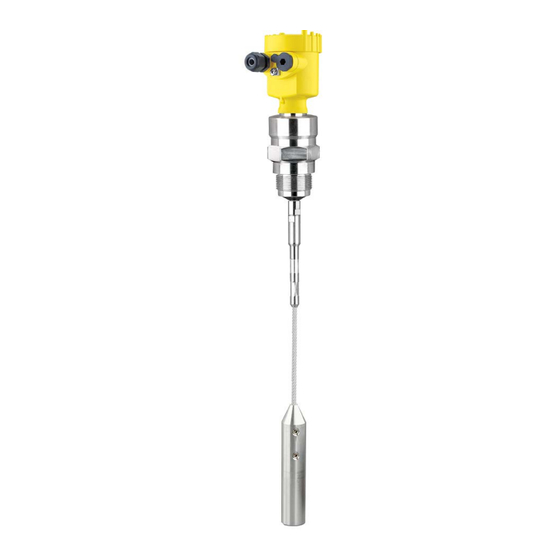
Tdr sensor for continuous level measurement of bulk solids, two-wire 4...20 ma/hart, rod and cable probe
Hide thumbs
Also See for VEGAFLEX 82:
- Operating instructions manual (96 pages) ,
- Quick setup manual (20 pages) ,
- Supplementary instructions manual (24 pages)

Related Manuals for Vega VEGAFLEX 82


Summary of Contents for Vega VEGAFLEX 82
- Page 1 Operating Instructions TDR sensor for continuous level measurement of bulk solids VEGAFLEX 82 Two-wire 4 … 20 mA/HART Rod and cable probe Document ID: 41829...
-
Page 2: Table Of Contents
Sensor parameter adjustment ..................47 Setup with PACTware ......................48 Connect the PC ......................48 Parameter adjustment with PACTware ................48 Set up with the quick setup ..................... 50 Save parameter adjustment data..................51 VEGAFLEX 82 • Two-wire 4 … 20 mA/HART... - Page 3 12.4 Trademark ........................84 Safety instructions for Ex areas: Take note of the Ex specific safety instructions for Ex applications. These instructions are attached as documents to each instrument with Ex approval and are part of the operating instructions. Editing status: 2023-05-23 VEGAFLEX 82 • Two-wire 4 … 20 mA/HART...
-
Page 4: About This Document
Symbols used Document ID This symbol on the front page of this instruction refers to the Docu- ment ID. By entering the Document ID on www.vega.com you will reach the document download. Information, note, tip: This symbol indicates helpful additional infor- mation and tips for successful work. -
Page 5: For Your Safety
During work on and with the device, the required personal protective equipment must always be worn. Appropriate use VEGAFLEX 82 is a sensor for continuous level measurement. You can find detailed information about the area of application in chapter " Product description". Operational reliability is ensured only if the instrument is properly used according to the specifications in the operating instructions manual as well as possible supplementary instructions. -
Page 6: Namur Recommendations
That is why we have introduced an environment management system with the goal of continuously improving company environmental pro- tection. The environment management system is certified according to DIN EN ISO 14001. Please help us fulfil this obligation by observing the environmental instructions in this manual: • Chapter " Packaging, transport and storage" • Chapter " Disposal" VEGAFLEX 82 • Two-wire 4 … 20 mA/HART... -
Page 7: Product Description
Scope of this operating This operating instructions manual applies to the following instrument instructions versions: • Hardware from 1.0.0 • Software from 1.3.0 • Only for instrument versions without SIL qualification Type label The type label contains the most important data for identification and use of the instrument: VEGAFLEX 82 • Two-wire 4 … 20 mA/HART... -
Page 8: Principle Of Operation
• Enter the serial number manually in the app Principle of operation The VEGAFLEX 82 is a level sensor with cable or rod probe for con- Application area tinuous level measurement, suitable for applications in bulk solids. VEGAFLEX 82 • Two-wire 4 … 20 mA/HART... -
Page 9: Packaging, Transport And Storage
The integrated Bluetooth module (optional) enables wireless adjust- ment via standard adjustment devices. The interface adapter VEGACONNECT enables the connection of VEGACONNECT communication-capable instruments to the USB interface of a PC. VEGAFLEX 82 • Two-wire 4 … 20 mA/HART... - Page 10 Curved segments: 100 x 100 mm (3.94 … 3.94 in) Centering If you mount the VEGAFLEX 82 in a bypass tube or standpipe, you have to avoid contact to the bypass tube by using a spacer at the probe end.
-
Page 11: Mounting
Note: Process conditions For safety reasons, the instrument must only be operated within the permissible process conditions. You can find detailed information on the process conditions in chapter " Technical data" of the operating instructions or on the type label. VEGAFLEX 82 • Two-wire 4 … 20 mA/HART... -
Page 12: Mounting Instructions
The guided microwave principle requires a metallic surface on the process fitting. Therefore, in plastic vessels, etc., use an instru- ment version with flange (from DN 50) or place a metal sheet (ø > 200 mm/8 in) beneath the process fitting when screwing it in. Make sure that the plate has direct contact with the process fitting. When using the probes without metal vessel wall, e.g. in plastic vessels, the measured value can be influenced by strong electromag- netic fields (emitted interference according to EN 61326: class A). Use a probe in coax version for applications in liquids. VEGAFLEX 82 • Two-wire 4 … 20 mA/HART... - Page 13 4 Mounting Fig. 3: Mounting in non-metallic vessel Flange Metal sheet Concrete vessel When mounting in thick concrete ceilings, VEGAFLEX 82 should be mounted front flush to the lower edge. In concrete silos, the distance to the wall should be at least 500 mm (20 in). ø >160 mm (ø >6.3") Fig.
- Page 14 Unfavourable mounting 2 Nozzle flush - optimum mounting Welding work Before beginning the welding work, remove the electronics module from the sensor. By doing this, you avoid damage to the electronics through inductive coupling. Inflowing medium Do not mount the instruments in or above the filling stream. Make sure that you detect the medium surface, not the inflowing product. VEGAFLEX 82 • Two-wire 4 … 20 mA/HART...
- Page 15 If there is a danger of the rod probe touching the vessel wall, fasten the probe at the bottom end. Keep in mind that measurement is not possible below the fastening point. VEGAFLEX 82 • Two-wire 4 … 20 mA/HART...
- Page 16 To compensate for the resulting changes in signal runtime, let the instrument determine the probe length automatically. You can find further information in the supplementary instructions of the rod and cable components. VEGAFLEX 82 • Two-wire 4 … 20 mA/HART...
-
Page 17: Connecting To Power Supply
You have to remove these plugs before electrical connection. NPT thread: In the case of instrument housings with self-sealing NPT threads, it is not possible to have the cable entries screwed in at the factory. The VEGAFLEX 82 • Two-wire 4 … 20 mA/HART... -
Page 18: Connecting
1. Unscrew the housing lid 2. If a display and adjustment module is installed, remove it by turn- ing it slightly to the left 3. Loosen compression nut of the cable gland and remove blind plug VEGAFLEX 82 • Two-wire 4 … 20 mA/HART... -
Page 19: Wiring Plan, Single Chamber Housing
10. Reinsert the display and adjustment module, if one was installed 11. Screw the housing lid back on The electrical connection is finished. Wiring plan, single chamber housing The following illustration applies to the non-Ex, Ex ia and Ex d version. VEGAFLEX 82 • Two-wire 4 … 20 mA/HART... -
Page 20: Wiring Plan, Double Chamber Housing
The following illustration applies to the non-Ex, Ex ia and Ex d version. Electronics compartment 4...20mA 6 7 8 Fig. 11: Electronics compartment - double chamber housing Internal connection to the connection compartment For display and adjustment module or interface adapter VEGAFLEX 82 • Two-wire 4 … 20 mA/HART... - Page 21 For display and adjustment module or interface adapter For external display and adjustment unit Ground terminal for connection of the cable screening Connection compart- ment - Radio module PLICSMOBILE 81 Status Send Fig. 13: Connection compartment - Radio module PLICSMOBILE 81 Voltage supply You can find detailed information for connection in the operating instructions " PLICSMOBILE". VEGAFLEX 82 • Two-wire 4 … 20 mA/HART...
-
Page 22: Wiring Plan, Ex D Ia Double Chamber Housing
(optional) Note: HART multidrop mode is not possible when using an Ex d ia instru- ment. Connection compartment 4...20mA Fig. 15: Connection compartment - Ex d ia double chamber housing Voltage supply, signal output Ground terminal for connection of the cable screening VEGAFLEX 82 • Two-wire 4 … 20 mA/HART... -
Page 23: Double Chamber Housing With Vegadis-Adapter
Pin 1 Pin 2 Pin 3 Pin 4 Contact pin Colour, connection ca- Terminal, electronics ble in the sensor module Pin 1 Brown Pin 2 White Pin 3 Blue Pin 4 Black VEGAFLEX 82 • Two-wire 4 … 20 mA/HART... -
Page 24: Wiring Plan - Version Ip66/Ip68 (1 Bar)
PC • The output signal jumps briefly to the set fault current Then the actual measured value is output to the signal cable. The value takes into account settings that have already been carried out, e.g. default setting. VEGAFLEX 82 • Two-wire 4 … 20 mA/HART... -
Page 25: Set Up With The Display And Adjustment Module
The display and adjustment module is powered by the sensor, an ad- ditional connection is not necessary. Fig. 20: Installing the display and adjustment module in the electronics compart- ment of the single chamber housing VEGAFLEX 82 • Two-wire 4 … 20 mA/HART... -
Page 26: Adjustment System
– Confirm selected menu – Edit parameter – Save value • [->] key: – Change measured value presentation – Select list entry – Select editing position • [+] key: – Change value of the parameter VEGAFLEX 82 • Two-wire 4 … 20 mA/HART... - Page 27 [OK] will not be saved. Switch-on phase After switching on, the VEGAFLEX 82 carries out a short self-test where the device software is checked. The output signal transmits a fault signal during the switch-on phase. The following information is displayed on the display and adjustment module during the startup procedure: •...
-
Page 28: Parameter Adjustment - Quick Setup
• False signal suppression You can find the description of the individual menu items in the follow- ing chapter " Parameter adjustment - Extended adjustment". Parameter adjustment - Extended adjustment For technically demanding measuring points, you can carry out extended settings in " Extended adjustment". The main menu is divided into five sections with the following func- Main menu tions: VEGAFLEX 82 • Two-wire 4 … 20 mA/HART... - Page 29 For the distance units you can choose between m, mm and ft and for the temperature units °C, °F and K. Probe length In this menu item you can enter the probe length or have the length determined automatically by the sensor system. VEGAFLEX 82 • Two-wire 4 … 20 mA/HART...
- Page 30 1.5 … 3 Granules, cement Lime, gypsum, cement < 1.5 Dusts, wood chips Wood chips, sawdust Max. adjustment level In this menu item, you can enter the max. adjustment for the level. VEGAFLEX 82 • Two-wire 4 … 20 mA/HART...
- Page 31 The default setting is a damping of 0 s. A linearisation is necessary for all vessels in which the vessel volume Linearisation does not increase linearly with the level, e.g. a horizontal cylindrical or spherical tank, when the indication or output of the volume is required. VEGAFLEX 82 • Two-wire 4 … 20 mA/HART...
- Page 32 For the vessel height, you have to enter the total height of the vessel. For the nozzle correction you have to enter the height of the nozzle above the upper edge of the vessel. If the nozzle is lower than the up- per edge of the vessel, this value can also be negative. Fig. 24: Vessel height and socket correction value D Vessel height +h Positive socket correction value -h Negative socket correction value VEGAFLEX 82 • Two-wire 4 … 20 mA/HART...
- Page 33 This should be done with the lowest possible level so that all potential interfering reflections can be detected. Proceed as follows: Enter the actual distance from the sensor to the medium surface. All interfering signals in this section are detected by the sensor and stored. VEGAFLEX 82 • Two-wire 4 … 20 mA/HART...
- Page 34 In menu item" Current output 2" you specify which measured value the additional current output refers to. The procedure corresponds to the previous settings of the standard current output. See " Setup - Current output". VEGAFLEX 82 • Two-wire 4 … 20 mA/HART...
- Page 35 The default setting for the displayed value 1 is " Filling height Level". Displayed value 2 In this menu item, you define the indication of the measured value on the display. You can display two different measured values. In this menu item, you define measured value 2. The default setting for the displayed value 2 is the electronics tem- perature. Display format In this menu item, you define the display format of the measured value on the display. You can define different display formats for the two measured values. You can thus define the number of decimal positions the measured value is displayed with. VEGAFLEX 82 • Two-wire 4 … 20 mA/HART...
- Page 36 The higher the value, the more reliable the measurement. In another window you can reset the peak value. VEGAFLEX 82 • Two-wire 4 … 20 mA/HART...
- Page 37 In this menu item you can simulate measured values via the current output. This allows the signal path to be tested, e.g. through down- stream indicating instruments or the input card of the control system. VEGAFLEX 82 • Two-wire 4 … 20 mA/HART...
- Page 38 6.4.4 Additional adjustments Date/Time In this menu item, the internal clock of the sensor is set. VEGAFLEX 82 • Two-wire 4 … 20 mA/HART...
- Page 39 Bulk solid Application Level in the metallic vessel Medium, dielectric constant Cereals, flour, sand / > 3 Superimposed gas phase Max. adjustment - Level 100 % Max. adjustment - Level Distance: 0.000 m(d) - note blocking distances VEGAFLEX 82 • Two-wire 4 … 20 mA/HART...
- Page 40 Menu - Display Menu item Default value Language Selected language Displayed value 1 Filling height Level Displayed value 2 Electronics temperature Display format 1 Automatically Display format 2 Automatically Backlight Switched on VEGAFLEX 82 • Two-wire 4 … 20 mA/HART...
- Page 41 TAG number this sensor had. Tip: We recommend to save the instrument adjustments. In case of an electronics exchange the saved parameter adjustment data relieve this process. VEGAFLEX 82 • Two-wire 4 … 20 mA/HART...
- Page 42 In menu item " Current output, variable" you specify which measured output size variable the current output refers to. Current output - Current In menu item " Current output, adjustment" you can assign a respec- output adjustment tive measured value to the current output. VEGAFLEX 82 • Two-wire 4 … 20 mA/HART...
- Page 43 Device name In this menu, you read out the instrument name and the instrument serial number. Instrument version In this menu item, the hardware and software version of the sensor is displayed. VEGAFLEX 82 • Two-wire 4 … 20 mA/HART...
-
Page 44: Save Parameter Adjustment Data
In the display and adjust- If the instrument is equipped with a display and adjustment module, ment module the parameter adjustment data can be saved therein. The procedure is described in menu item " Copy device settings". VEGAFLEX 82 • Two-wire 4 … 20 mA/HART... -
Page 45: Set Up With Smartphone/Tablet/Pc/Notebook Via Bluetooth
PIN in the adjustment menu of the respective sensor, e.g. to " 1111". Use " OK" to switch to the input menu. Basic adjustment Display Diagnostics Service Info Deactivate permanently? VEGAFLEX 82 • Two-wire 4 … 20 mA/HART... -
Page 46: Connecting
Bluetooth-capable instru- ments in the area. PC/Notebook Start PACTware and the VEGA project assistant. Select the device search via Bluetooth and start the search function. The device auto- matically searches for Bluetooth-capable devices in the vicinity. -
Page 47: Sensor Parameter Adjustment
After successful authentication, the next con- nection functions without authentication. For authentication, enter in the next menu window the 4-digit sensor PIN. Sensor parameter adjustment The sensor parameterization is carried out via the adjustment app on the smartphone/tablet or the DTM on the PC/notebook. App view Fig. 26: Example of an app view - Setup sensor adjustment VEGAFLEX 82 • Two-wire 4 … 20 mA/HART... -
Page 48: Setup With Pactware
Note: With power supply units with integrated HART resistance (internal resistance approx. 250 Ω), an additional external resistance is not necessary. This applies, e.g. to the VEGA instruments VEGAMET 381, VEGAMET 391. Common Ex separators are also usually equipped with a sufficient current limiting resistance. In such cases, the interface adapter can be connected parallel to the 4 … 20 mA cable (dashed line in the previous illustration). - Page 49 In addition, there is a tank calculation program as well as a multiviewer for display and analysis of the saved measured value and echo curves. VEGAFLEX 82 • Two-wire 4 … 20 mA/HART...
-
Page 50: Set Up With The Quick Setup
2 Extended adjustment Maintenance Quick setup With quick setup you can carry out the parameter adjustment of VEGAFLEX 82 for your application in just a few simple steps. The assistant-driven adjustment includes the basic settings for simple, reliable setup and commissioning. Information: If the function is inactive, then possibly no instrument is connected. -
Page 51: Save Parameter Adjustment Data
Click to the button " Quick setup", to start the assistant-driven adjust- ment for a simplified and reliable setup. Save parameter adjustment data We recommend documenting or saving the parameterisation data via PACTware. That way the data are available for multiple use or service purposes. VEGAFLEX 82 • Two-wire 4 … 20 mA/HART... -
Page 52: Set Up With Other Systems
This software is updated via the Internet and new EDDs are automatically accepted into the device catalogue of this software after they are released by the manufacturer. They can then be transferred to a Field Communicator. VEGAFLEX 82 • Two-wire 4 … 20 mA/HART... -
Page 53: Diagnosis, Asset Management And Service
• Switch-on and switch-off times • Status messages (according to NE 107) • Error messages (according to NE 107) The data are read out via a PC with PACTware/DTM or the control system with EDD. VEGAFLEX 82 • Two-wire 4 … 20 mA/HART... -
Page 54: Asset Management Function
This status message is always active. It cannot be deactivated by the user. Function check: The instrument is being worked on, the measured value is temporarily invalid (for example during simulation). This status message is inactive by default. VEGAFLEX 82 • Two-wire 4 … 20 mA/HART... - Page 55 EMC interference Remove EMC influences Bit 12 of Byte 0 … 5 Communica- Transmission error during ex- Exchange four-wire power sup- tion error ternal communication with ply unit or electronics four-wire power supply unit VEGAFLEX 82 • Two-wire 4 … 20 mA/HART...
- Page 56 Level echo in the close range not Reduce level Bit 9 of available Byte 14 … 24 Overfilling 100 % adjustment: Increase value Check mounting socket Remove possible interfering signals in the close range Use coaxial probe VEGAFLEX 82 • Two-wire 4 … 20 mA/HART...
-
Page 57: Rectify Faults
The operator of the system is responsible for taking suitable meas- tion occurs ures to rectify faults. Fault rectification The first measures are: • Evaluation of fault messages • Checking the output signal • Treatment of measurement errors VEGAFLEX 82 • Two-wire 4 … 20 mA/HART... - Page 58 If the output level is constant, the cause could also be the fault setting of the output to " Hold value". If the level is too low, the reason could be a line resistance that is too high VEGAFLEX 82 • Two-wire 4 … 20 mA/HART...
- Page 59 Eliminate false signals in the close range ≥ 100 % or 0 m distance close range due to false signals in the Check installation conditions close range. The sensor goes into over- If possible, switch off the function "Over- fill protection mode. The max. level (0 m fill protection" distance) as well as the status message "Overfill protection" are output. time VEGAFLEX 82 • Two-wire 4 … 20 mA/HART...
-
Page 60: Exchanging The Electronics Module
24 hour service hotline Should these measures not be successful, please call in urgent cases the VEGA service hotline under the phone no. +49 1805 858550. The hotline is also available outside normal working hours, seven days a week around the clock. -
Page 61: Exchange Or Shorten Cable/Rod
20 Nm (15 lbf ft). Fig. 33: Exchange cable or rod Information: Please maintain the specified torque so that the max. tensile strength of the connection remains. 6. Enter new probe length and if necessary the new probe type and then carry out a fresh adjustment (see " Setup procedure, Carry- ing out min. adjustment - Carrying out max. adjustment"). VEGAFLEX 82 • Two-wire 4 … 20 mA/HART... - Page 62 8. Enter new probe length and then carry out a fresh adjustment (see " Setup procedure, Carrying out min. adjustment - Carrying out max. adjustment"). Fig. 34: Shortening the cable probe A Gravity weight - cable ø 4 mm B Gravity weight - cable ø 6 mm Threaded pins Thread M12 for eye-bolt Threaded pins VEGAFLEX 82 • Two-wire 4 … 20 mA/HART...
-
Page 63: Software Update
Attach the completed form and, if need be, also a safety data sheet outside on the packaging • Ask the agency serving you to get the address for the return ship- ment. You can find the agency on our homepage. VEGAFLEX 82 • Two-wire 4 … 20 mA/HART... -
Page 64: Dismount
If personal data is stored on the old device to be disposed of, delete it before disposal. If you have no way to dispose of the old instrument properly, please contact us concerning return and disposal. VEGAFLEX 82 • Two-wire 4 … 20 mA/HART... -
Page 65: Supplement
Ʋ Supporting material 316L Ʋ Glass potting Borosilicate glass GPC 540 Ʋ Contacts Alloy C22 (2.4602) Only with Ex-d version. Aluminium, stainless steel precision casting and Ex d housing Only with Ex-d version. VEGAFLEX 82 • Two-wire 4 … 20 mA/HART... - Page 66 Ʋ Cable: ø 6 mm (0.236 in) 30 KN (6744 lbf) Ʋ Cable: ø 11 mm (0.433 in), PA coated 30 KN (6744 lbf) The tensile force of solids are subject of a normal fluctuation range. For this reason, the determined diagram value of the following diagrams must be multiplied with safety factor 2. VEGAFLEX 82 • Two-wire 4 … 20 mA/HART...
- Page 67 Tensile force in kN (the determined value must be multiplied with safety factor 2) Cable length in m Vessel diameter 12 m (39.37 ft) Vessel diameter 9 m (29.53 ft) Vessel diameter 6 m (19.69 ft) Vessel diameter 3 m (9.843 ft) VEGAFLEX 82 • Two-wire 4 … 20 mA/HART...
- Page 68 Vessel diameter 6 m (19.69 ft) Vessel diameter 3 m (9.843 ft) Thread in gravity weight, e.g. for eye-bolt M 12 (cable version) Torque for exchangeable cable or rod probe (in the process fitting) Ʋ Cable: ø 4 mm (0.157 in) 8 Nm (5.9 lbf ft) VEGAFLEX 82 • Two-wire 4 … 20 mA/HART...
- Page 69 Ʋ Displayed value 1 Filling height Level Ʋ Displayed value 2 Electronics temperature Resolution, digital < 1 mm (0.039 in) The output values can be assigned individually. The indication values can be assigned individually. VEGAFLEX 82 • Two-wire 4 … 20 mA/HART...
- Page 70 Ʋ Medium Bulk solids - cereals, flour, cement (dielectric con- stant ~2.0) Ʋ Mounting Probe end does not touch the vessel bottom Sensor parameter adjustment No gating out of false signals carried out The indication values can be assigned individually. VEGAFLEX 82 • Two-wire 4 … 20 mA/HART...
- Page 71 Reference plane Probe length L Measuring range Upper blocking distance (see following diagrams - grey section) Lower blocking distance (see following diagrams - grey section) Typical deviation See following diagrams Depending on the mounting conditions, deviations can occur which can be rectified by adapting the adjustment or changing the measured value offset in the DTM service mode. VEGAFLEX 82 • Two-wire 4 … 20 mA/HART...
- Page 72 0,15 m (5.906 ") Fig. 41: Deviation VEGAFLEX 82 in cable version Blocking distance (no measurement possible in this area) Probe length Non-repeatability ≤ ±1 mm Variables influencing measurement accuracy Specifications for the digital measured value Temperature drift - Digital output ±3 mm/10 K relating to the max. measuring range or max. 10 mm (0.394 in) VEGAFLEX 82 • Two-wire 4 … 20 mA/HART...
- Page 73 -40 … +80 °C (-40 … +176 °F) Also for the additional current output (optional). Time span after a sudden measuring distance change by max. 0.5 m in liquid applications, max 2 m with bulk solids applications, until the output signal has taken for the first time 90 % of the final value (IEC 61298-2). VEGAFLEX 82 • Two-wire 4 … 20 mA/HART...
- Page 74 122°F 176°F 212°F 302°F -40°C / -40°F Fig. 42: Ambient temperature - process temperature, standard version Ambient temperature Process temperature (depending on the seal material) Aluminium housing Plastic housing Stainless steel housing (precision casting) Stainless steel housing (electropolished) VEGAFLEX 82 • Two-wire 4 … 20 mA/HART...
- Page 75 6 … 12 mm 7 … 12 mm 10 … 14 mm – ● ● – ● Brass, nickel- ● ● ● – – plated Stainless – ● ● – ● steel VEGAFLEX 82 • Two-wire 4 … 20 mA/HART...
- Page 76 Ʋ Output Via the respective output signal Voltage supply Operating voltage U 9.6 … 35 V DC Operating voltage U with lighting 16 … 35 V DC switched on Reverse voltage protection Integrated VEGAFLEX 82 • Two-wire 4 … 20 mA/HART...
-
Page 77: Dimensions
Ʋ with connected overvoltage protection up to 5000 m (16404 ft) Pollution degree (with fulfilled housing protection) Protection rating (IEC 61010-1) 12.2 Dimensions The following dimensional drawings represent only an extract of all possible versions. Detailed dimensional drawings can be downloaded at www.vega.com/downloads under " Drawings". VEGAFLEX 82 • Two-wire 4 … 20 mA/HART... - Page 78 ~ 116 mm ~ 87 mm (3.43") (4.57") ø 86 mm ø 86 mm (3.39") (3.39") M16x1,5 M20x1,5 M20x1,5/ ½ NPT M20x1,5/ ½ NPT Fig. 45: Housing versions with protection rating IP66/IP68 (0.2 bar), (with integrated display and adjustment mod- ule the housing is 9 mm/0.35 in higher) Aluminium - single chamber Aluminium - double chamber VEGAFLEX 82 • Two-wire 4 … 20 mA/HART...
- Page 79 (3.15") (3.11") M16x1,5 M20x1,5/ ½ NPT M20x1,5/ M20x1,5/ ½ NPT ½ NPT Fig. 47: Housing versions with protection rating IP66/IP68 (0.2 bar), (with integrated display and adjustment mod- ule the housing is 9 mm/0.35 in higher) Stainless steel single chamber (electropolished) Stainless steel single chamber (precision casting) Stainless steel double chamber housing (precision casting) VEGAFLEX 82 • Two-wire 4 … 20 mA/HART...
- Page 80 ø 84 mm (3.31") (3.31") (3.03") M16x1,5 M20x1,5 M20x1,5 M20x1,5 M20x1,5/ ½ NPT Fig. 48: Housing versions in protection IP66/IP68 (1 bar),(with integrated display and adjustment module the hous- ing is 9 mm/0.35 in higher) Stainless steel single chamber (electropolished) Stainless steel single chamber (precision casting) Stainless steel double chamber housing (precision casting) VEGAFLEX 82 • Two-wire 4 … 20 mA/HART...
- Page 81 12 Supplement VEGAFLEX 82, cable version ø 4 mm (0.157 in), ø 6 mm (0.236 in), PA coated SW 36 mm (1.42") G ¾ ø 6 mm ø 4 mm (0.24") (0.16") ø 20 mm (0.79") Fig. 49: VEGAFLEX 82, cable ø 4 mm (0.157 in), ø 6 mm (0.236 in) threaded version with gravity weight (all gravity weights with thread M12 for eye-bolt) Sensor length, see chapter "...
- Page 82 12 Supplement VEGAFLEX 82, cable version ø 6 mm (0.236 in), ø 11 mm (0.433 in), PA coated SW 55 mm (2.17") G1½ ø 6 mm ø 11 mm (0.24") (0.43") ø 30 mm (1.18") Fig. 50: VEGAFLEX 82, cable ø 6 mm (0.236 in), ø 11 mm (0.433 in) threaded version with gravity weight (all grav- ity weights with thread M12 for eye-bolt) Sensor length, see chapter "...
- Page 83 12 Supplement VEGAFLEX 82, rod version ø 16 mm (0.63 in) SW 55 mm (2.17") G1½ ø 16 mm (0.63") Fig. 51: VEGAFLEX 82, rod ø 16 mm (0.63 in), threaded version Sensor length, see chapter " Technical data" Joint - rod VEGAFLEX 82 • Two-wire 4 … 20 mA/HART...
-
Page 84: Industrial Property Rights
Les lignes de produits VEGA sont globalement protégées par des droits de propriété intellec- tuelle. Pour plus d'informations, on pourra se référer au site www.vega.com. VEGA lineas de productos están protegidas por los derechos en el campo de la propiedad indus- trial. Para mayor información revise la pagina web www.vega.com. - Page 85 – Spacer 10 Reset 39 Factory calibration date 44 False signal suppression 33 Fault rectification 57 Scaling measured value 42 Functional principle 9 Sensor characteristics 44 Service hotline 60 Simulation 37 Grounding 18 Special parameters 43 VEGAFLEX 82 • Two-wire 4 … 20 mA/HART...
- Page 86 INDEX Type label 7 Type of medium 30 Units 29 VEGAFLEX 82 • Two-wire 4 … 20 mA/HART...
- Page 87 Notes VEGAFLEX 82 • Two-wire 4 … 20 mA/HART...
- Page 88 Subject to change without prior notice © VEGA Grieshaber KG, Schiltach/Germany 2023 VEGA Grieshaber KG Am Hohenstein 113 Phone +49 7836 50-0 77761 Schiltach E-mail: info.de@vega.com...
Need help?
Do you have a question about the VEGAFLEX 82 and is the answer not in the manual?
Questions and answers